US8212913B2 - Zoom lens system, imaging device and camera - Google Patents
Zoom lens system, imaging device and camera Download PDFInfo
- Publication number
- US8212913B2 US8212913B2 US12/676,048 US67604808A US8212913B2 US 8212913 B2 US8212913 B2 US 8212913B2 US 67604808 A US67604808 A US 67604808A US 8212913 B2 US8212913 B2 US 8212913B2
- Authority
- US
- United States
- Prior art keywords
- lens unit
- lens
- zoom lens
- wide
- condition
- Prior art date
- Legal status (The legal status is an assumption and is not a legal conclusion. Google has not performed a legal analysis and makes no representation as to the accuracy of the status listed.)
- Expired - Fee Related, expires
Links
Images


Classifications
-
- G—PHYSICS
- G02—OPTICS
- G02B—OPTICAL ELEMENTS, SYSTEMS OR APPARATUS
- G02B15/00—Optical objectives with means for varying the magnification
- G02B15/14—Optical objectives with means for varying the magnification by axial movement of one or more lenses or groups of lenses relative to the image plane for continuously varying the equivalent focal length of the objective
- G02B15/144—Optical objectives with means for varying the magnification by axial movement of one or more lenses or groups of lenses relative to the image plane for continuously varying the equivalent focal length of the objective having four groups only
- G02B15/1441—Optical objectives with means for varying the magnification by axial movement of one or more lenses or groups of lenses relative to the image plane for continuously varying the equivalent focal length of the objective having four groups only the first group being positive
- G02B15/144113—Optical objectives with means for varying the magnification by axial movement of one or more lenses or groups of lenses relative to the image plane for continuously varying the equivalent focal length of the objective having four groups only the first group being positive arranged +-++
-
- G—PHYSICS
- G02—OPTICS
- G02B—OPTICAL ELEMENTS, SYSTEMS OR APPARATUS
- G02B15/00—Optical objectives with means for varying the magnification
- G02B15/14—Optical objectives with means for varying the magnification by axial movement of one or more lenses or groups of lenses relative to the image plane for continuously varying the equivalent focal length of the objective
- G02B15/145—Optical objectives with means for varying the magnification by axial movement of one or more lenses or groups of lenses relative to the image plane for continuously varying the equivalent focal length of the objective having five groups only
- G02B15/1451—Optical objectives with means for varying the magnification by axial movement of one or more lenses or groups of lenses relative to the image plane for continuously varying the equivalent focal length of the objective having five groups only the first group being positive
- G02B15/145129—Optical objectives with means for varying the magnification by axial movement of one or more lenses or groups of lenses relative to the image plane for continuously varying the equivalent focal length of the objective having five groups only the first group being positive arranged +-+++
Definitions
- the present invention relates to a zoom lens system, an imaging device and a camera.
- the present invention relates to: a zoom lens system having a reduced size and still realizing a wide view angle at a wide-angle limit, as well as a remarkably high zooming ratio and high performance; an imaging device employing this zoom lens system; and a thin and compact camera employing this imaging device.
- zoom lens systems having high zooming ratios and suitable for the above-mentioned digital cameras for example, the following zoom lens systems have been proposed.
- Japanese Laid-Open Patent Publication No. 2006-171655 discloses an image-taking optical system at least comprising a first lens unit having positive optical power, a second lens unit having negative optical power, a third lens unit having positive optical power, and a fourth lens unit having positive optical power, wherein any of the lens unit intervals is changed so that variable magnification is achieved, and wherein the ratio between the focal length of the third lens unit and the focal length of the fourth lens unit and the ratio between the focal length of the first lens unit and the focal length of the entire optical system at a wide-angle limit are set forth.
- Japanese Laid-Open Patent Publication No. 2006-184413 discloses an image-taking optical system at least comprising a first lens unit having positive optical power, a second lens unit having negative optical power, a third lens unit having positive optical power, and a fourth lens unit having positive optical power, wherein at least the first lens unit is moved so that variable magnification is achieved, and wherein the ratio between the distance from the surface located on the most image-taking object side in the first lens unit at a wide-angle limit to the image formation surface and the focal length of the entire optical system at a telephoto limit and the ratio between the focal length of the first lens unit and the focal length of the entire optical system at a wide-angle limit are set forth.
- Japanese Laid-Open Patent Publication No. 2006-184416 discloses an image-taking optical system at least comprising a first lens unit having positive optical power, a second lens unit having negative optical power, a third lens unit having positive optical power, and a fourth lens unit having positive optical power, wherein any of the lens unit intervals is changed so that variable magnification is achieved, and wherein the ratio between the focal length of the first lens unit and the focal length of the entire optical system at a wide-angle limit, the ratio between the ratio of the focal length of the second lens unit at a telephoto limit and at a wide-angle limit and the ratio of the focal length of the entire optical system at a telephoto limit and at a wide-angle limit, and the ratio between the magnification of the third lens unit at a telephoto limit and the magnification of the third lens unit at a wide-angle limit are set forth.
- Japanese Laid-Open Patent Publication No. 2006-189598 discloses an image-taking optical system at least comprising a first lens unit having positive optical power, a second lens unit having negative optical power, a third lens unit having positive optical power, and a fourth lens unit having positive optical power, wherein the third lens unit at least includes two positive optical power lenses and one negative optical power lens, wherein at least the second, the third, and the fourth lens units are moved so that variable magnification is achieved, and wherein the ratio between the focal length of the first lens unit and the focal length of the entire optical system at a wide-angle limit, the ratio between the focal length of the negative optical power lens in the third lens unit and the focal length of the third lens unit, and the refractive index of the negative optical power lens in the third lens unit are set forth.
- Japanese Laid-Open Patent Publication No. 2007-003554 discloses a variable magnification optical system at least comprising a first lens unit having positive optical power, a second lens unit having negative optical power, a third lens unit having positive optical power, and a fourth lens unit having positive optical power, wherein at least the first and the third lens units are moved so that variable magnification is achieved, wherein in this magnification change, the first lens unit is moved to the object side, and wherein the ratio between the amount of relative movement of the second lens unit at the time of magnification change and the focal length of the entire optical system at a wide-angle limit, the ratio between the focal length of the first lens unit and the focal length of the entire optical system at a wide-angle limit, and the ratio between the focal length of the third lens unit and the focal length of the entire optical system at a telephoto limit are set forth.
- Japanese Laid-Open Patent Publication No. 2007-010695 discloses a variable magnification optical system at least comprising a first lens unit having positive optical power, a second lens unit having negative optical power, a third lens unit having positive optical power, and a fourth lens unit having positive optical power, wherein at least the first lens unit is moved so that variable magnification is achieved, and wherein the ratio between the focal length of the first lens unit and the focal length of the entire optical system at a wide-angle limit and the average refractive index to the d-line of all lenses in the second lens unit are set forth.
- optical systems disclosed in the above-mentioned publications have high zooming ratios sufficient for application to digital cameras. Nevertheless, width of the view angle at a wide-angle limit and size reduction are not simultaneously realized. In particular, from the viewpoint of size reduction, requirements in digital cameras of recent years are not satisfied.
- Objects of the present invention are to provide: a zoom lens system having a reduced size and still realizing a wide view angle at a wide-angle limit, as well as a remarkably high zooming ratio and high performance; an imaging device employing this zoom lens system; and a thin and compact camera employing this imaging device.
- a zoom lens system in order from an object side to an image side, comprising a first lens unit having positive optical power, a second lens unit having negative optical power, a third lens unit having positive optical power, and a fourth lens unit having positive optical power, wherein
- ⁇ is a half view angle (°) at a wide-angle limit
- L W is an overall optical axial length of the entire system at a wide-angle limit (a distance from the most object side surface to the most image side surface),
- f 3 is a focal length of the third lens unit
- f 4 is a focal length of the fourth lens unit
- f T is a focal length of the entire system at a telephoto limit
- f W is a focal length of the entire system at a wide-angle limit.
- the present invention relates to
- an imaging device capable of outputting an optical image of an object as an electric image signal comprising:
- the zoom lens system in order from an object side to an image side, comprises a first lens unit having positive optical power, a second lens unit having negative optical power, a third lens unit having positive optical power, and a fourth lens unit having positive optical power, wherein
- ⁇ is a half view angle (°) at a wide-angle limit
- L W is an overall optical axial length of the entire system at a wide-angle limit (a distance from the most object side surface to the most image side surface),
- f 3 is a focal length of the third lens unit
- f 4 is a focal length of the fourth lens unit
- f T is a focal length of the entire system at a telephoto limit
- f W is a focal length of the entire system at a wide-angle limit.
- the present invention relates to
- a camera for converting an optical image of an object into an electric image signal and then performing at least one of displaying and storing of the converted image signal, comprising
- an imaging device including a zoom lens system that forms the optical image of the object and an image sensor that converts the optical image formed by the zoom lens system into the electric image signal, wherein
- the zoom lens system in order from an object side to an image side, comprises a first lens unit having positive optical power, a second lens unit having negative optical power, a third lens unit having positive optical power, and a fourth lens unit having positive optical power, wherein
- ⁇ is a half view angle (°) at a wide-angle limit
- L W is an overall optical axial length of the entire system at a wide-angle limit (a distance from the most object side surface to the most image side surface),
- f 3 is a focal length of the third lens unit
- f 4 is a focal length of the fourth lens unit
- f T is a focal length of the entire system at a telephoto limit
- f W is a focal length of the entire system at a wide-angle limit.
- a zoom lens system in order from an object side to an image side, comprising a first lens unit having positive optical power, a second lens unit having negative optical power, a third lens unit having positive optical power, and a fourth lens unit having positive optical power, wherein
- the second lens unit includes a lens element having negative optical power and being arranged on the most object side and a lens element having positive optical power, and wherein
- nd 4 is a refractive index to the d-line of a lens element having negative optical power and being arranged on the most object side in the second lens unit,
- nd 6 is a refractive index to the d-line of a lens element having positive optical power in the second lens unit
- ⁇ is a half view angle (°) at a wide-angle limit
- f T is a focal length of the entire system at a telephoto limit
- f W is a focal length of the entire system at a wide-angle limit.
- the present invention relates to
- an imaging device capable of outputting an optical image of an object as an electric image signal comprising:
- the zoom lens system in order from an object side to an image side, comprises a first lens unit having positive optical power, a second lens unit having negative optical power, a third lens unit having positive optical power, and a fourth lens unit having positive optical power, wherein
- the second lens unit includes a lens element having negative optical power and being arranged on the most object side and a lens element having positive optical power, and wherein
- nd 4 is a refractive index to the d-line of a lens element having negative optical power and being arranged on the most object side in the second lens unit,
- nd 6 is a refractive index to the d-line of a lens element having positive optical power in the second lens unit
- ⁇ is a half view angle (°) at a wide-angle limit
- f T is a focal length of the entire system at a telephoto limit
- f W is a focal length of the entire system at a wide-angle limit.
- the present invention relates to
- a camera for converting an optical image of an object into an electric image signal and then performing at least one of displaying and storing of the converted image signal, comprising
- an imaging device including a zoom lens system that forms the optical image of the object and an image sensor that converts the optical image formed by the zoom lens system into the electric image signal, wherein
- the zoom lens system in order from an object side to an image side, comprises a first lens unit having positive optical power, a second lens unit having negative optical power, a third lens unit having positive optical power, and a fourth lens unit having positive optical power, wherein
- the second lens unit includes a lens element having negative optical power and being arranged on the most object side and a lens element having positive optical power, and wherein
- nd 4 is a refractive index to the d-line of a lens element having negative optical power and being arranged on the most object side in the second lens unit,
- nd 6 is a refractive index to the d-line of a lens element having positive optical power in the second lens unit
- ⁇ is a half view angle (°) at a wide-angle limit
- f T is a focal length of the entire system at a telephoto limit
- f W is a focal length of the entire system at a wide-angle limit.
- a zoom lens system in order from an object side to an image side, comprising a first lens unit having positive optical power, a second lens unit having negative optical power, a third lens unit having positive optical power, and a fourth lens unit having positive optical power, wherein
- the first lens unit includes a lens element having negative optical power and being arranged on the most object side, and at least two lens elements having positive optical power that include a lens element having positive optical power and being arranged on the most image side, and wherein
- nd 1 is a refractive index to the d-line of a lens element having negative optical power and being arranged on the most object side in the first lens unit,
- nd 2 is a refractive index to the d-line of a lens element located on the most object side among the lens elements having positive optical power in the first lens unit,
- nd 3 is a refractive index to the d-line of a lens element having positive optical power and being arranged on the most image side in the first lens unit,
- ⁇ is a half view angle (°) at a wide-angle limit
- f T is a focal length of the entire system at a telephoto limit
- f W is a focal length of the entire system at a wide-angle limit.
- the present invention relates to
- an imaging device capable of outputting an optical image of an object as an electric image signal comprising:
- the zoom lens system in order from an object side to an image side, comprises a first lens unit having positive optical power, a second lens unit having negative optical power, a third lens unit having positive optical power, and a fourth lens unit having positive optical power, wherein
- the first lens unit includes a lens element having negative optical power and being arranged on the most object side, and at least two lens elements having positive optical power that include a lens element having positive optical power and being arranged on the most image side, and wherein
- nd 1 is a refractive index to the d-line of a lens element having negative optical power and being arranged on the most object side in the first lens unit,
- nd 2 is a refractive index to the d-line of a lens element located on the most object side among the lens elements having positive optical power in the first lens unit,
- nd 3 is a refractive index to the d-line of a lens element having positive optical power and being arranged on the most image side in the first lens unit,
- ⁇ is a half view angle (°) at a wide-angle limit
- f T is a focal length of the entire system at a telephoto limit
- f W is a focal length of the entire system at a wide-angle limit.
- the present invention relates to
- a camera for converting an optical image of an object into an electric image signal and then performing at least one of displaying and storing of the converted image signal, comprising
- an imaging device including a zoom lens system that forms the optical image of the object and an image sensor that converts the optical image formed by the zoom lens system into the electric image signal, wherein
- the zoom lens system in order from an object side to an image side, comprises a first lens unit having positive optical power, a second lens unit having negative optical power, a third lens unit having positive optical power, and a fourth lens unit having positive optical power, wherein
- the first lens unit includes a lens element having negative optical power and being arranged on the most object side, and at least two lens elements having positive optical power that include a lens element having positive optical power and being arranged on the most image side, and wherein
- nd 1 is a refractive index to the d-line of a lens element having negative optical power and being arranged on the most object side in the first lens unit,
- nd 2 is a refractive index to the d-line of a lens element located on the most object side among the lens elements having positive optical power in the first lens unit,
- nd 3 is a refractive index to the d-line of a lens element having positive optical power and being arranged on the most image side in the first lens unit,
- ⁇ is a half view angle (°) at a wide-angle limit
- f T is a focal length of the entire system at a telephoto limit
- f W is a focal length of the entire system at a wide-angle limit.
- a zoom lens system in order from an object side to an image side, comprising a first lens unit having positive optical power, a second lens unit having negative optical power, and subsequent lens units, wherein
- the subsequent lens units include at least a third lens unit having positive optical power and a fourth lens unit having positive optical power, wherein
- the first lens unit, the second lens unit, the third lens unit and the fourth lens unit move along an optical axis, and wherein
- m 2T is a lateral magnification of the second lens unit at a telephoto limit
- m 34T is a lateral magnification at a telephoto limit of a composite lens unit consisting of all lens units located on the image side relative to the second lens unit,
- ⁇ is a half view angle (°) at a wide-angle limit
- f T is a focal length of the entire system at a telephoto limit
- f W is a focal length of the entire system at a wide-angle limit.
- the present invention relates to
- an imaging device capable of outputting an optical image of an object as an electric image signal comprising:
- the zoom lens system in order from an object side to an image side, comprises a first lens unit having positive optical power, a second lens unit having negative optical power, and subsequent lens units, wherein
- the subsequent lens units include at least a third lens unit having positive optical power and a fourth lens unit having positive optical power, wherein
- the first lens unit, the second lens unit, the third lens unit and the fourth lens unit move along an optical axis, and wherein
- m 2T is a lateral magnification of the second lens unit at a telephoto limit
- m 34T is a lateral magnification at a telephoto limit of a composite lens unit consisting of all lens units located on the image side relative to the second lens unit,
- ⁇ is a half view angle (°) at a wide-angle limit
- f T is a focal length of the entire system at a telephoto limit
- f W is a focal length of the entire system at a wide-angle limit.
- the present invention relates to
- a camera for converting an optical image of an object into an electric image signal and then performing at least one of displaying and storing of the converted image signal, comprising
- an imaging device including a zoom lens system that forms the optical image of the object and an image sensor that converts the optical image formed by the zoom lens system into the electric image signal, wherein
- the zoom lens system in order from an object side to an image side, comprises a first lens unit having positive optical power, a second lens unit having negative optical power, and subsequent lens units, wherein
- the subsequent lens units include at least a third lens unit having positive optical power and a fourth lens unit having positive optical power, wherein
- the first lens unit, the second lens unit, the third lens unit and the fourth lens unit move along an optical axis, and wherein
- m 2T is a lateral magnification of the second lens unit at a telephoto limit
- m 34T is a lateral magnification at a telephoto limit of a composite lens unit consisting of all lens units located on the image side relative to the second lens unit,
- ⁇ is a half view angle (°) at a wide-angle limit
- f T is a focal length of the entire system at a telephoto limit
- f W is a focal length of the entire system at a wide-angle limit.
- the present invention provides a zoom lens system having a reduced size and still realizes a wide view angle at a wide-angle limit, as well as a remarkably high zooming ratio and high performance. Further, according to the present invention, an imaging device employing this zoom lens system and a thin and compact camera employing this imaging device are provided.
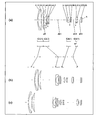
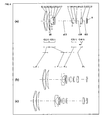
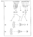
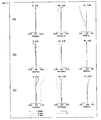
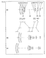
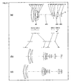
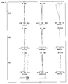
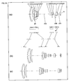
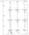
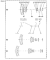
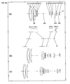
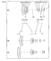
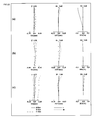
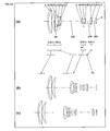
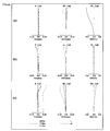
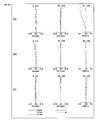
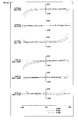
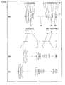
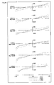
- FIG. 1 is a lens arrangement diagram showing an infinity in-focus condition of a zoom lens system according to Embodiment I-1 (Example I-1).
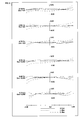
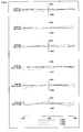
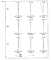
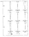
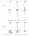
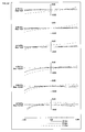
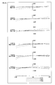
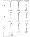
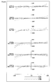
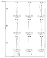
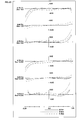
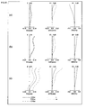
- FIG. 2 is a longitudinal aberration diagram of an infinity in-focus condition of a zoom lens system according to Example I-1.
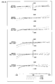
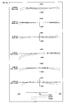
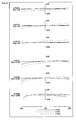
- FIG. 3 is a lateral aberration diagram in a basic state where image blur compensation is not performed and in an image blur compensation state at a telephoto limit of a zoom lens system according to Example I-1.
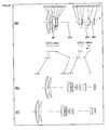
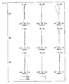
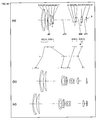
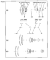
- FIG. 4 is a lens arrangement diagram showing an infinity in-focus condition of a zoom lens system according to Embodiment I-2 (Example I-2).
- FIG. 5 is a longitudinal aberration diagram of an infinity in-focus condition of a zoom lens system according to Example I-2.
- FIG. 6 is a lateral aberration diagram in a basic state where image blur compensation is not performed and in an image blur compensation state at a telephoto limit of a zoom lens system according to Example I-2.
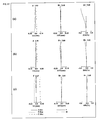
- FIG. 7 is a lens arrangement diagram showing an infinity in-focus condition of a zoom lens system according to Embodiment I-3 (Example I-3).
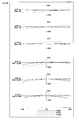
- FIG. 8 is a longitudinal aberration diagram of an infinity in-focus condition of a zoom lens system according to Example I-3.
- FIG. 9 is a lateral aberration diagram in a basic state where image blur compensation is not performed and in an image blur compensation state at a telephoto limit of a zoom lens system according to Example I-3.
- FIG. 10 is a lens arrangement diagram showing an infinity in-focus condition of a zoom lens system according to Embodiment I-4 (Example I-4).
- FIG. 11 is a longitudinal aberration diagram of an infinity in-focus condition of a zoom lens system according to Example I-4.
- FIG. 12 is a lateral aberration diagram in a basic state where image blur compensation is not performed and in an image blur compensation state at a telephoto limit of a zoom lens system according to Example I-4.
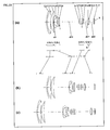
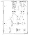
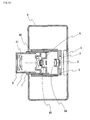
- FIG. 13 is a schematic construction diagram of a digital still camera according to Embodiment I-5.
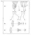
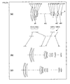
- FIG. 14 is a lens arrangement diagram showing an infinity in-focus condition of a zoom lens system according to Embodiment II-1 (Example II-1).
- FIG. 15 is a longitudinal aberration diagram of an infinity in-focus condition of a zoom lens system according to Example II-1.
- FIG. 16 is a lateral aberration diagram in a basic state where image blur compensation is not performed and in an image blur compensation state at a telephoto limit of a zoom lens system according to Example II-1.
- FIG. 17 is a lens arrangement diagram showing an infinity in-focus condition of a zoom lens system according to Embodiment II-2 (Example II-2).
- FIG. 18 is a longitudinal aberration diagram of an infinity in-focus condition of a zoom lens system according to Example II-2.
- FIG. 19 is a lateral aberration diagram in a basic state where image blur compensation is not performed and in an image blur compensation state at a telephoto limit of a zoom lens system according to Example II-2.
- FIG. 20 is a lens arrangement diagram showing an infinity in-focus condition of a zoom lens system according to Embodiment II-3 (Example II-3).
- FIG. 21 is a longitudinal aberration diagram of an infinity in-focus condition of a zoom lens system according to Example II-3.
- FIG. 22 is a lateral aberration diagram in a basic state where image blur compensation is not performed and in an image blur compensation state at a telephoto limit of a zoom lens system according to Example II-3.
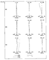
- FIG. 23 is a lens arrangement diagram showing an infinity in-focus condition of a zoom lens system according to Embodiment II-4 (Example II-4).
- FIG. 24 is a longitudinal aberration diagram of an infinity in-focus condition of a zoom lens system according to Example II-4.
- FIG. 25 is a lateral aberration diagram in a basic state where image blur compensation is not performed and in an image blur compensation state at a telephoto limit of a zoom lens system according to Example II-4.
- FIG. 26 is a lens arrangement diagram showing an infinity in-focus condition of a zoom lens system according to Embodiment II-5 (Example II-5).
- FIG. 27 is a longitudinal aberration diagram of an infinity in-focus condition of a zoom lens system according to Example II-5.
- FIG. 28 is a lateral aberration diagram in a basic state where image blur compensation is not performed and in an image blur compensation state at a telephoto limit of a zoom lens system according to Example II-5.
- FIG. 29 is a schematic construction diagram of a digital still camera according to Embodiment II-6.
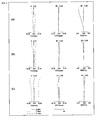
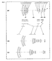
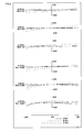
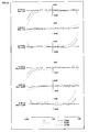
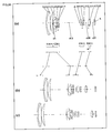
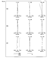
- FIG. 30 is a lens arrangement diagram showing an infinity in-focus condition of a zoom lens system according to Embodiment III-1 (Example III-1).
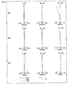
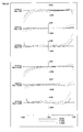
- FIG. 31 is a longitudinal aberration diagram of an infinity in-focus condition of a zoom lens system according to Example III-1.
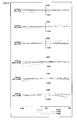
- FIG. 32 is a lateral aberration diagram in a basic state where image blur compensation is not performed and in an image blur compensation state at a telephoto limit of a zoom lens system according to Example III-1.
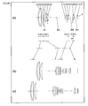
- FIG. 33 is a lens arrangement diagram showing an infinity in-focus condition of a zoom lens system according to Embodiment III-2 (Example III-2).
- FIG. 34 is a longitudinal aberration diagram of an infinity in-focus condition of a zoom lens system according to Example III-2.
- FIG. 35 is a lateral aberration diagram in a basic state where image blur compensation is not performed and in an image blur compensation state at a telephoto limit of a zoom lens system according to Example III-2.
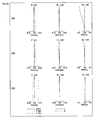
- FIG. 36 is a lens arrangement diagram showing an infinity in-focus condition of a zoom lens system according to Embodiment III-3 (Example III-3).
- FIG. 37 is a longitudinal aberration diagram of an infinity in-focus condition of a zoom lens system according to Example III-3.
- FIG. 38 is a lateral aberration diagram in a basic state where image blur compensation is not performed and in an image blur compensation state at a telephoto limit of a zoom lens system according to Example III-3.
- FIG. 39 is a lens arrangement diagram showing an infinity in-focus condition of a zoom lens system according to Embodiment III-4 (Example III-4).
- FIG. 40 is a longitudinal aberration diagram of an infinity in-focus condition of a zoom lens system according to Example III-4.
- FIG. 41 is a lateral aberration diagram in a basic state where image blur compensation is not performed and in an image blur compensation state at a telephoto limit of a zoom lens system according to Example III-4.
- FIG. 42 is a lens arrangement diagram showing an infinity in-focus condition of a zoom lens system according to Embodiment III-5 (Example III-5).
- FIG. 43 is a longitudinal aberration diagram of an infinity in-focus condition of a zoom lens system according to Example III-5.
- FIG. 44 is a lateral aberration diagram in a basic state where image blur compensation is not performed and in an image blur compensation state at a telephoto limit of a zoom lens system according to Example III-5.
- FIG. 45 is a lens arrangement diagram showing an infinity in-focus condition of a zoom lens system according to Embodiment III-6 (Example III-6).
- FIG. 46 is a longitudinal aberration diagram of an infinity in-focus condition of a zoom lens system according to Example III-6.
- FIG. 47 is a lateral aberration diagram in a basic state where image blur compensation is not performed and in an image blur compensation state at a telephoto limit of a zoom lens system according to Example III-6.
- FIG. 48 is a lens arrangement diagram showing an infinity in-focus condition of a zoom lens system according to Embodiment III-7 (Example III-7).
- FIG. 49 is a longitudinal aberration diagram of an infinity in-focus condition of a zoom lens system according to Example III-7.
- FIG. 50 is a lateral aberration diagram in a basic state where image blur compensation is not performed and in an image blur compensation state at a telephoto limit of a zoom lens system according to Example III-7.
- FIG. 51 is a schematic construction diagram of a digital still camera according to Embodiment III-8.
- FIG. 52 is a lens arrangement diagram showing an infinity in-focus condition of a zoom lens system according to Embodiment IV-1 (Example IV-1).
- FIG. 53 is a longitudinal aberration diagram of an infinity in-focus condition of a zoom lens system according to Example IV-1.
- FIG. 54 is a lateral aberration diagram in a basic state where image blur compensation is not performed and in an image blur compensation state at a telephoto limit of a zoom lens system according to Example IV-1.
- FIG. 55 is a lens arrangement diagram showing an infinity in-focus condition of a zoom lens system according to Embodiment IV-2 (Example IV-2).
- FIG. 56 is a longitudinal aberration diagram of an infinity in-focus condition of a zoom lens system according to Example IV-2.
- FIG. 57 is a lateral aberration diagram in a basic state where image blur compensation is not performed and in an image blur compensation state at a telephoto limit of a zoom lens system according to Example IV-2.
- FIG. 58 is a lens arrangement diagram showing an infinity in-focus condition of a zoom lens system according to Embodiment IV-3 (Example IV-3).
- FIG. 59 is a longitudinal aberration diagram of an infinity in-focus condition of a zoom lens system according to Example IV-3.
- FIG. 60 is a lateral aberration diagram in a basic state where image blur compensation is not performed and in an image blur compensation state at a telephoto limit of a zoom lens system according to Example IV-3.
- FIG. 61 is a lens arrangement diagram showing an infinity in-focus condition of a zoom lens system according to Embodiment IV-4 (Example IV-4).
- FIG. 62 is a longitudinal aberration diagram of an infinity in-focus condition of a zoom lens system according to Example IV-4.
- FIG. 63 is a lateral aberration diagram in a basic state where image blur compensation is not performed and in an image blur compensation state at a telephoto limit of a zoom lens system according to Example IV-4.
- FIG. 64 is a lens arrangement diagram showing an infinity in-focus condition of a zoom lens system according to Embodiment IV-5 (Example IV-5).
- FIG. 65 is a longitudinal aberration diagram of an infinity in-focus condition of a zoom lens system according to Example IV-5.
- FIG. 66 is a lateral aberration diagram in a basic state where image blur compensation is not performed and in an image blur compensation state at a telephoto limit of a zoom lens system according to Example IV-5.
- FIG. 67 is a schematic construction diagram of a digital still camera according to Embodiment IV-6.
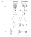
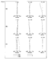
- FIG. 1 is a lens arrangement diagram of a zoom lens system according to Embodiment I-1.
- FIG. 4 is a lens arrangement diagram of a zoom lens system according to Embodiment I-2.
- FIG. 7 is a lens arrangement diagram of a zoom lens system according to Embodiment I-3.
- FIG. 10 is a lens arrangement diagram of a zoom lens system according to Embodiment I-4.
- FIGS. 1 , 4 , 7 and 10 show respectively a zoom lens system in an infinity in-focus condition.
- part (a) shows a lens configuration at a wide-angle limit (in the minimum focal length condition: focal length f W )
- part (c) shows a lens configuration at a telephoto limit (in the maximum focal length condition: focal length f T ).
- bent arrows provided between part (a) and part (b) are lines obtained by connecting the positions of the lens units at a wide-angle limit, at a middle position and at a telephoto limit, in order from the top to the bottom.
- straight lines are used simply between a wide-angle limit and a middle position and between a middle position and a telephoto limit. That is, these straight lines do not indicate the actual motion of the individual lens units.
- an arrow provided to a lens unit indicates focusing from an infinity in-focus condition to a close-object in-focus condition, that is, the moving direction at the time of focusing from an infinity in-focus condition to a close-object in-focus condition.
- the zoom lens system according to each embodiment in order from the object side to the image side, comprises a first lens unit G 1 having positive optical power, a second lens unit G 2 having negative optical power, a third lens unit G 3 having positive optical power, and a fourth lens unit G 4 having positive optical power. Then, in zooming from a wide-angle limit to a telephoto limit, the first lens unit G 1 , the second lens unit G 2 , the third lens unit G 3 and the fourth lens unit G 4 all move along the optical axis (this lens configuration is referred to as the basic configuration I of Embodiments I-1 to I-4, hereinafter). In the zoom lens system according to each embodiment, these lens units are arranged into a desired optical power arrangement, so that a remarkably high zooming ratio exceeding 16 and high optical performance are achieved and still size reduction is realized in the entire lens system.
- an asterisk “*” provided to a particular surface indicates that the surface is aspheric.
- a symbol (+) or ( ⁇ ) provided to the sign of each lens unit corresponds to the sign of optical power of the lens unit.
- the straight line located on the most right-hand side indicates the position of an image surface S.
- a plane parallel plate such as an optical low-pass filter and a face plate of an image sensor is provided.
- a diaphragm A is provided between the most image side lens surface of the second lens unit G 2 and the most object side lens surface of the third lens unit G 3 .
- the first lens unit G 1 in order from the object side to the image side, comprises: a negative meniscus first lens element L 1 with the convex surface facing the object side; a bi-convex second lens element L 2 ; and a positive meniscus third lens element L 3 with the convex surface facing the object side.
- the first lens element L 1 and the second lens element L 2 are cemented with each other.
- the second lens unit G 2 in order from the object side to the image side, comprises: a negative meniscus fourth lens element L 4 with the convex surface facing the object side; a bi-concave fifth lens element L 5 ; a bi-convex sixth lens element L 6 ; and a bi-concave seventh lens element L 7 .
- the sixth lens element L 6 and the seventh lens element L 7 are cemented with each other.
- the third lens unit G 3 in order from the object side to the image side, comprises: a positive meniscus eighth lens element L 8 with the convex surface facing the object side; a bi-convex ninth lens element L 9 ; and a bi-concave tenth lens element L 10 .
- the ninth lens element L 9 and the tenth lens element L 10 are cemented with each other.
- the fourth lens unit G 4 in order from the object side to the image side, comprises: a bi-convex eleventh lens element L 11 ; and a negative meniscus twelfth lens element L 12 with the convex surface facing the image side.
- the eleventh lens element L 11 and the twelfth lens element L 12 are cemented with each other.
- a plane parallel plate L 13 is provided on the object side relative to the image surface S (between the image surface S and the twelfth lens element L 12 ).
- the zoom lens system according to Embodiment I-1 in zooming from a wide-angle limit to a telephoto limit, the first lens unit G 1 and the third lens unit G 3 move to the object side, while the second lens unit G 2 moves to the image side, that is, such that the position at a wide-angle limit should be located on the object side relative to the position at a telephoto limit. Further, the fourth lens unit G 4 moves with locus of a convex to the object side with changing the interval with the third lens unit G 3 .
- the first lens unit G 1 in order from the object side to the image side, comprises: a negative meniscus first lens element L 1 with the convex surface facing the object side; a positive meniscus second lens element L 2 with the convex surface facing the object side; and a positive meniscus third lens element L 3 with the convex surface facing the object side.
- the first lens element L 1 and the second lens element L 2 are cemented with each other.
- the second lens unit G 2 in order from the object side to the image side, comprises: a negative meniscus fourth lens element L 4 with the convex surface facing the object side; a bi-concave fifth lens element L 5 ; a bi-convex sixth lens element L 6 ; and a negative meniscus seventh lens element L 7 with the convex surface facing the image side.
- the sixth lens element L 6 and the seventh lens element L 7 are cemented with each other.
- the third lens unit G 3 in order from the object side to the image side, comprises: a bi-convex eighth lens element L 8 ; a bi-convex ninth lens element L 9 ; and a bi-concave tenth lens element L 10 .
- the ninth lens element L 9 and the tenth lens element L 10 are cemented with each other.
- the fourth lens unit G 4 in order from the object side to the image side, comprises: a bi-convex eleventh lens element L 11 ; and a negative meniscus twelfth lens element L 12 with the convex surface facing the image side.
- the eleventh lens element L 11 and the twelfth lens element L 12 are cemented with each other.
- a plane parallel plate L 13 is provided on the object side relative to the image surface S (between the image surface S and the twelfth lens element L 12 ).
- the zoom lens system according to Embodiment I-2 in zooming from a wide-angle limit to a telephoto limit, the first lens unit G 1 and the third lens unit G 3 move to the object side, while the second lens unit G 2 moves to the image side, that is, such that the position at a wide-angle limit should be located on the object side relative to the position at a telephoto limit. Further, the fourth lens unit G 4 moves with locus of a convex to the object side with changing the interval with the third lens unit G 3 .
- the first lens unit G 1 in order from the object side to the image side, comprises: a negative meniscus first lens element L 1 with the convex surface facing the object side; a positive meniscus second lens element L 2 with the convex surface facing the object side; and a positive meniscus third lens element L 3 with the convex surface facing the object side.
- the first lens element L 1 and the second lens element L 2 are cemented with each other.
- the second lens unit G 2 in order from the object side to the image side, comprises: a negative meniscus fourth lens element L 4 with the convex surface facing the object side; a bi-concave fifth lens element L 5 ; a bi-convex sixth lens element L 6 ; and a bi-concave seventh lens element L 7 .
- the sixth lens element L 6 and the seventh lens element L 7 are cemented with each other.
- the third lens unit G 3 in order from the object side to the image side, comprises: a positive meniscus eighth lens element L 8 with the convex surface facing the object side; a bi-convex ninth lens element L 9 ; and a bi-concave tenth lens element L 10 .
- the ninth lens element L 9 and the tenth lens element L 10 are cemented with each other.
- the fourth lens unit G 4 in order from the object side to the image side, comprises: a bi-convex eleventh lens element L 11 ; and a negative meniscus twelfth lens element L 12 with the convex surface facing the image side.
- the eleventh lens element L 11 and the twelfth lens element L 12 are cemented with each other.
- a plane parallel plate L 13 is provided on the object side relative to the image surface S (between the image surface S and the twelfth lens element L 12 ).
- the zoom lens system according to Embodiment I-3 in zooming from a wide-angle limit to a telephoto limit, the first lens unit G 1 and the third lens unit G 3 move to the object side, while the second lens unit G 2 moves to the image side, that is, such that the position at a wide-angle limit should be located on the object side relative to the position at a telephoto limit. Further, the fourth lens unit G 4 moves with locus of a convex to the object side with changing the interval with the third lens unit G 3 .
- the first lens unit G 1 in order from the object side to the image side, comprises: a negative meniscus first lens element L 1 with the convex surface facing the object side; a bi-convex second lens element L 2 ; and a positive meniscus third lens element L 3 with the convex surface facing the object side.
- the first lens element L 1 and the second lens element L 2 are cemented with each other.
- the second lens unit G 2 in order from the object side to the image side, comprises: a negative meniscus fourth lens element L 4 with the convex surface facing the object side; a bi-concave fifth lens element L 5 ; a bi-convex sixth lens element L 6 ; and a bi-concave seventh lens element L 7 .
- the sixth lens element L 6 and the seventh lens element L 7 are cemented with each other.
- the third lens unit G 3 in order from the object side to the image side, comprises: a positive meniscus eighth lens element L 8 with the convex surface facing the object side; a bi-convex ninth lens element L 9 ; and a bi-concave tenth lens element L 10 .
- the ninth lens element L 9 and the tenth lens element L 10 are cemented with each other.
- the fourth lens unit G 4 in order from the object side to the image side, comprises: a bi-convex eleventh lens element L 11 ; and a negative meniscus twelfth lens element L 12 with the convex surface facing the image side.
- the eleventh lens element L 11 and the twelfth lens element L 12 are cemented with each other.
- a plane parallel plate L 13 is provided on the object side relative to the image surface S (between the image surface S and the twelfth lens element L 12 ).
- the zoom lens system according to Embodiment I-4 in zooming from a wide-angle limit to a telephoto limit, the first lens unit G 1 and the third lens unit G 3 move to the object side, while the second lens unit G 2 moves to the image side, that is, such that the position at a wide-angle limit should be located on the object side relative to the position at a telephoto limit. Further, the fourth lens unit G 4 moves with locus of a convex to the object side with changing the interval with the third lens unit G 3 .
- the first lens unit G 1 , the second lens unit G 2 , the third lens unit G 3 and the fourth lens unit G 4 all move along the optical axis.
- the third lens unit is moved in a direction perpendicular to the optical axis, so that image blur caused by hand blurring, vibration and the like can be compensated optically.
- the third lens unit moves in a direction perpendicular to the optical axis as described above, so that image blur is compensated in a state that size increase in the entire zoom lens system is suppressed and a compact construction is realized and that excellent imaging characteristics such as small decentering coma aberration and decentering astigmatism are satisfied.
- f T is a focal length of the entire system at a telephoto limit
- f W is a focal length of the entire system at a wide-angle limit
- ⁇ is a half view angle (°) at a wide-angle limit.
- the zoom lens system having the basic configuration I satisfies the following condition (1). 0 ⁇ ( f 4 ⁇ f W ⁇ tan ⁇ )/ L W ⁇ 0.13 (1)
- ⁇ is a half view angle (°) at a wide-angle limit
- L W is an overall optical axial length of the entire system at a wide-angle limit (a distance from the most object side surface to the most image side surface),
- f 4 is a focal length of the fourth lens unit
- f W is a focal length of the entire system at a wide-angle limit.
- the condition (1) substantially sets forth the focal length of the fourth lens unit.
- the optical power of the fourth lens unit is excessively weak, and hence the necessary amount of movement in zooming increases.
- the value exceeds the upper limit of the condition (1) it becomes difficult to achieve a satisfactory peripheral illuminance on the image surface especially at a wide-angle limit.
- the zoom lens system having the basic configuration I satisfies the following condition (2) with satisfying the above-mentioned condition (1). 0.05 ⁇ f 3 /f 4 ⁇ 0.97 (2)
- f 3 is a focal length of the third lens unit
- f 4 is a focal length of the fourth lens unit.
- the condition (2) sets forth the ratio between the focal length of the third lens unit and the focal length of the fourth lens unit.
- the focal length of the third lens unit is excessively long.
- the amount of movement of the third lens unit necessary for achieving a high magnification exceeding 16 increases excessively.
- the value exceeds the upper limit of the condition (2) a problem arises that it becomes difficult, for example, for the third lens unit to be moved in a direction perpendicular to the optical axis for blur compensation.
- the focal length of the third lens unit is excessively short.
- a large aberration fluctuation arises in zooming so as to cause difficulty in compensation.
- a zoom lens system having the above-mentioned basic configuration I like each zoom lens system according to Embodiments I-1 to I-4 especially in a case that the second lens unit includes a lens element having negative optical power and being arranged on the most object side and a lens element having positive optical power, it is preferable that the following condition (3) is satisfied. ( nd 4 ⁇ 1)+( nd 6 ⁇ 1) ⁇ 1.8 (3)
- nd 4 is a refractive index to the d-line of a lens element having negative optical power and being arranged on the most object side in the second lens unit, and
- nd 6 is a refractive index to the d-line of a lens element having positive optical power in the second lens unit.
- the condition (3) sets forth a condition desired to be satisfied by lens elements contained in the second lens unit.
- the value falls outside the range of the condition (3), compensation of distortion and curvature of field is difficult especially at a wide-angle limit. Thus, this situation is not preferable.
- dG 3 is an optical axial center thickness of the third lens unit
- dG is a sum of the optical axial thicknesses of the first lens unit, the second lens unit, the third lens unit and the fourth lens unit.
- the condition (8) sets forth the optical axial thickness of the third lens unit.
- the thickness of the third lens unit is excessively great, and hence it is difficult in some cases to achieve a compact lens system.
- the thickness of the third lens unit is excessively great, and hence it becomes difficult that, for example, the third lens unit is moved in a direction perpendicular to the optical axis for blur compensation.
- the value goes below the lower limit of the condition (8), difficulty arises in compensating various kinds of aberration to be compensated by the third lens unit, especially in compensating spherical aberration and coma aberration at a wide-angle limit. Thus, this situation is not preferable.
- f 2 is a focal length of the second lens unit
- f 3 is a focal length of the third lens unit
- f 4 is a focal length of the fourth lens unit.
- the condition (9) sets forth the focal lengths of the lens units.
- the value exceeds the upper limit of the condition (9) the absolute value of the optical power of the second lens unit is relatively strong excessively.
- the absolute value of the optical power of the second lens unit is relatively weak excessively.
- the necessary amount of movement of the second lens unit is excessively great.
- this situation is not preferable.
- m 2T is a lateral magnification of the second lens unit at a telephoto limit
- m 34T is a lateral magnification at a telephoto limit of a composite lens unit consisting of all lens units located on the image side relative to the second lens unit.
- the condition (I-10) sets forth the magnification of the lens units at a telephoto limit.
- the value exceeds the upper limit of the condition (I-10) the overall length at a telephoto limit is excessively great, and hence difficulty arises in realizing a compact zoom lens system. Further, for example, in a case that the lens units on the image side relative to the second lens unit are moved in a direction perpendicular to the optical axis so that blur compensation is achieved, an excessively large aberration fluctuation is caused. Thus, this situation is not preferable.
- d1NG is an optical axial center thickness of the lens element having negative optical power contained in the first lens unit
- d1G is an optical axial center thickness of the first lens unit.
- the condition (11) sets forth the thickness of the lens element having negative optical power contained in the first lens unit.
- the value exceeds the upper limit of the condition (11) the thickness of the entirety of the first lens unit is excessively great, and hence it is difficult to achieve a compact zoom lens system. Thus, this situation is not preferable.
- the value goes below the lower limit of the condition (11) remarkable difficulty arises in fabricating the lens element having negative optical power contained in the first lens unit. Thus, this situation is not preferable.
- condition (11)′ or condition (11)′′ and condition (11)′′′ when at least one of either condition (11)′ or condition (11)′′ and condition (11)′′′ is satisfied, the above-mentioned effect is achieved more successfully.
- f W is a focal length of the entire system at a wide-angle limit
- ⁇ is a half view angle (real half view angle (°)) at a wide-angle limit
- ⁇ is a paraxial half view angle (°) at a wide-angle limit.
- the condition (12) sets forth the difference between the real half view angle and the paraxial half view angle at a wide-angle limit. This condition substantially controls distortion. When the value falls outside the range of the condition (12), distortion is excessively great. Thus, this situation is not preferable.
- f 4 is a focal length of the fourth lens unit
- f T is a focal length of the entire system at a telephoto limit.
- the condition (13) sets forth the optical power of the fourth lens unit.
- the focal length of the fourth lens unit is excessively long, that is, the optical power is excessively weak.
- difficulty arises in appropriately controlling the exit pupil position especially at a wide-angle limit. Accordingly, it is difficult in some cases to achieve a satisfactory image surface illuminance
- the focal length of the fourth lens unit is excessively short, that is, the optical power is excessively strong.
- M 1 is an amount of movement of the first lens unit in the optical axis direction during zooming from a wide-angle limit to a telephoto limit (movement from the image side to the object side is defined to be positive), and
- M 2 is an amount of movement of the second lens unit in the optical axis direction during zooming from a wide-angle limit to a telephoto limit (movement from the image side to the object side is defined to be positive).
- the condition (14) sets forth the amount of movement of the first lens unit in the optical axis direction.
- the value exceeds the upper limit of the condition (14) the amount of movement of the first lens unit is excessively large.
- the effective diameter of the first lens unit necessary for achieving a satisfactory F-number at a wide-angle limit increases. This causes difficulty in some cases in achieving a compact zoom lens system.
- the value goes below the lower limit of the condition (14) the amount of movement of the second lens unit necessary for achieving a satisfactory high magnification is relatively large excessively. Thus, it is difficult in some cases to achieve a compact zoom lens system.
- M 2 is an amount of movement of the second lens unit in the optical axis direction during zooming from a wide-angle limit to a telephoto limit (movement from the image side to the object side is defined to be positive), and
- M 3 is an amount of movement of the third lens unit in the optical axis direction during zooming from a wide-angle limit to a telephoto limit (movement from the image side to the object side is defined to be positive).
- the condition (15) sets forth the amount of movement of the third lens unit in the optical axis direction.
- the value exceeds the upper limit of the condition (15) the amount of movement of the third lens unit is excessively large.
- an excessively large aberration fluctuation is generated in the third lens unit during zooming Accordingly, it is difficult in some cases to compensate this aberration by other lens units.
- the value goes below the lower limit of the condition (15) the amount of movement of the third lens unit is excessively small.
- a relatively excessively large amount of movement of the second lens unit is necessary for achieving a high magnification. Accordingly, it is difficult in some cases to achieve a compact zoom lens system.
- m 2T is a lateral magnification of the second lens unit at a telephoto limit
- m 2W is a lateral magnification of the second lens unit at a wide-angle limit
- f T is a focal length of the entire system at a telephoto limit
- f W is a focal length of the entire system at a wide-angle limit.
- the condition (16) sets forth a lateral magnification change in the second lens unit and substantially sets forth the degree of variable magnification load to the second lens unit.
- the variable magnification load to the second lens unit is excessive.
- the value goes below the lower limit of the condition (16)
- the variable magnification load to the second lens unit is excessively small.
- the amount of movement of the third lens unit during zooming necessary for achieving a satisfactory high magnification becomes relatively large. Accordingly, it is difficult in some cases to achieve size reduction of the entire zoom lens system.
- m 3T is a lateral magnification of the third lens unit at a telephoto limit
- m 3W is a lateral magnification of the third lens unit at a wide-angle limit.
- the condition (17) sets forth a lateral magnification change in the third lens unit and substantially sets forth the degree of variable magnification load to the third lens unit.
- the variable magnification load to the third lens unit is excessive.
- difficulty arises in compensating various kinds of aberration that vary during magnification change, especially, in compensating off-axial aberration.
- this situation is not preferable.
- the variable magnification load to the third lens unit is excessively small.
- a relatively excessively large amount of movement of the second lens unit is necessary for achieving a high magnification. Accordingly, it is difficult in some cases to achieve a compact zoom lens system.
- ⁇ is a half view angle (°) at a wide-angle limit
- f 3 is a focal length of the third lens unit
- f 4 is a focal length of the fourth lens unit
- f W is a focal length of the entire system at a wide-angle limit.
- the condition (18) sets forth the focal lengths of the third lens unit and the fourth lens unit.
- the focal lengths of the third lens unit and the fourth lens unit are excessively long. This causes difficulty in some cases in achieving a compact zoom lens system.
- the focal lengths of the third lens unit and the fourth lens unit are excessively short.
- aberration compensation capability especially of the third lens unit is excessive. Accordingly, it is difficult in some cases to achieve satisfactory balance of aberration compensation in the entire zoom lens system.
- ⁇ is a half view angle (°) at a wide-angle limit
- L T is an overall optical axial length of the entire system at a telephoto limit (a distance from the most object side surface to the most image side surface),
- L W is an overall optical axial length of the entire system at a wide-angle limit (a distance from the most object side surface to the most image side surface), and
- f W is a focal length of the entire system at a wide-angle limit.
- the condition (19) sets forth an overall length change during zooming When the value falls outside the range of the condition (19), it is difficult to construct a compact lens barrel mechanism. Thus, this situation is not preferable.
- ⁇ is a half view angle (°) at a wide-angle limit
- L T is an overall optical axial length of the entire system at a telephoto limit (a distance from the most object side surface to the most image side surface),
- f 4 is a focal length of the fourth lens unit
- f T is a focal length of the entire system at a telephoto limit
- f W is a focal length of the entire system at a wide-angle limit.
- the condition (20) sets forth a suitable overall length at a telephoto limit.
- the overall length at a telephoto limit is excessively long, and hence it is difficult in some cases to achieve a compact zoom lens system having a short overall length.
- the overall length at a telephoto limit is excessively long.
- the focal length of the fourth lens unit is, relatively, excessively long.
- this situation is not preferable.
- ⁇ is a half view angle (°) at a wide-angle limit
- L W is an overall optical axial length of the entire system at a wide-angle limit (a distance from the most object side surface to the most image side surface),
- f 4 is a focal length of the fourth lens unit
- f T is a focal length of the entire system at a telephoto limit
- f W is a focal length of the entire system at a wide-angle limit.
- the condition (21) sets forth a suitable overall length at a wide-angle limit.
- the value exceeds the upper limit of the condition (21)
- the overall length at a wide-angle limit is excessively long, and hence it is difficult in some cases to achieve a zoom lens system having a compact accommodation size.
- the focal length of the fourth lens unit is, relatively, excessively long.
- ⁇ is a half view angle (°) at a wide-angle limit
- f 3 is a focal length of the third lens unit
- f W is a focal length of the entire system at a wide-angle limit.
- the condition (22) sets forth the focal length of the third lens unit.
- the focal length of the third lens unit is excessively long. This causes difficulty in some cases in achieving a compact zoom lens system.
- the value exceeds the upper limit of the condition (22) the necessary amount of movement in a case that, for example, the third lens unit is moved in a direction perpendicular to the optical axis for blur compensation becomes excessively large. Thus, this situation is not preferable.
- the focal length of the third lens unit is excessively short.
- the aberration compensation capability of the third lens unit is excessive, and hence the compensation balance of various kinds of aberration is degraded. This causes difficulty in some cases in achieving a compact zoom lens system.
- the lens units constituting the zoom lens system of each embodiment are composed exclusively of refractive type lenses that deflect the incident light by refraction (that is, lenses of a type in which deflection is achieved at the interface between media each having a distinct refractive index).
- the lens type is not limited to this.
- the lens units may employ diffractive type lenses that deflect the incident light by diffraction; refractive-diffractive hybrid type lenses that deflect the incident light by a combination of diffraction and refraction; or gradient index type lenses that deflect the incident light by distribution of refractive index in the medium.
- a reflecting surface may be arranged in the optical path so that the optical path may be bent before, after or in the middle of the zoom lens system.
- the bending position may be set up in accordance with the necessity. When the optical path is bent appropriately, the apparent thickness of a camera can be reduced.
- This low-pass filter may be: a birefringent type low-pass filter made of, for example, a crystal whose predetermined crystal orientation is adjusted; or a phase type low-pass filter that achieves required characteristics of optical cut-off frequency by diffraction.
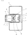
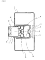
- FIG. 13 is a schematic construction diagram of a digital still camera according to Embodiment I-5.
- the digital still camera comprises: an imaging device having a zoom lens system 1 and an image sensor 2 composed of a CCD; a liquid crystal display monitor 3 ; and a body 4 .
- the employed zoom lens system 1 is a zoom lens system according to Embodiment I-1.
- the zoom lens system 1 comprises a first lens unit G 1 , a second lens unit G 2 , a diaphragm A, a third lens unit G 3 and a fourth lens unit G 4 .
- the zoom lens system 1 is arranged on the front side, while the image sensor 2 is arranged on the rear side of the zoom lens system 1 .
- the liquid crystal display monitor 3 is arranged, while an optical image of a photographic object generated by the zoom lens system 1 is formed on an image surface S.
- the lens barrel comprises a main barrel 5 , a moving barrel 6 and a cylindrical cam 7 .
- the first lens unit G 1 , the second lens unit G 2 , the third lens unit G 3 and the fourth lens unit G 4 move to predetermined positions relative to the image sensor 2 , so that magnification change can be achieved ranging from a wide-angle limit to a telephoto limit.
- the fourth lens unit G 4 is movable in an optical axis direction by a motor for focus adjustment.
- the zoom lens system according to Embodiment I-1 when employed in a digital still camera, a small digital still camera is obtained that has a high resolution and high capability of compensating the curvature of field and that has a short overall optical length of lens system at the time of non-use.
- any one of the zoom lens systems according to Embodiments I-2 to I-4 may be employed in place of the zoom lens system according to Embodiment I-1.
- the optical system of the digital still camera shown in FIG. 13 is applicable also to a digital video camera for moving images. In this case, moving images with high resolution can be acquired in addition to still images.
- an imaging device comprising a zoom lens system according to Embodiments I-1 to I-4 described above and an image sensor such as a CCD or a CMOS may be applied to a mobile telephone, a PDA (Personal Digital Assistance), a surveillance camera in a surveillance system, a Web camera, a vehicle-mounted camera or the like.
- a PDA Personal Digital Assistance
- a surveillance camera in a surveillance system a surveillance system
- a Web camera a vehicle-mounted camera or the like.
- FIG. 14 is a lens arrangement diagram of a zoom lens system according to Embodiment II-1.
- FIG. 17 is a lens arrangement diagram of a zoom lens system according to Embodiment II-2.
- FIG. 20 is a lens arrangement diagram of a zoom lens system according to Embodiment II-3.
- FIG. 23 is a lens arrangement diagram of a zoom lens system according to Embodiment II-4.
- FIG. 26 is a lens arrangement diagram of a zoom lens system according to Embodiment II-5.
- FIGS. 14 , 17 , 20 , 23 and 26 show respectively a zoom lens system in an infinity in-focus condition.
- part (a) shows a lens configuration at a wide-angle limit (in the minimum focal length condition: focal length f W )
- part (c) shows a lens configuration at a telephoto limit (in the maximum focal length condition: focal length f T ).
- bent arrows provided between part (a) and part (b) are lines obtained by connecting the positions of the lens units at a wide-angle limit, at a middle position and at a telephoto limit, in order from the top to the bottom.
- straight lines are used simply between a wide-angle limit and a middle position and between a middle position and a telephoto limit. That is, these straight lines do not indicate the actual motion of the individual lens units.
- an arrow provided to a lens unit indicates focusing from an infinity in-focus condition to a close-object in-focus condition, that is, the moving direction at the time of focusing from an infinity in-focus condition to a close-object in-focus condition.
- the zoom lens system according to each embodiment in order from the object side to the image side, comprises a first lens unit G 1 having positive optical power, a second lens unit G 2 having negative optical power, a third lens unit G 3 having positive optical power, and a fourth lens unit G 4 having positive optical power. Then, in zooming from a wide-angle limit to a telephoto limit, the first lens unit G 1 , the second lens unit G 2 , the third lens unit G 3 and the fourth lens unit G 4 all move along the optical axis (this lens configuration is referred to as the basic configuration II of Embodiments II-1 to II-5, hereinafter).
- these lens units are arranged into a desired optical power arrangement, so that a remarkably high zooming ratio exceeding 16 and high optical performance are achieved and still size reduction is realized in the entire lens system.
- an asterisk “*” provided to a particular surface indicates that the surface is aspheric.
- a symbol (+) or ( ⁇ ) provided to the sign of each lens unit corresponds to the sign of optical power of the lens unit.
- the straight line located on the most right-hand side indicates the position of an image surface S.
- a plane parallel plate such as an optical low-pass filter and a face plate of an image sensor is provided.
- a diaphragm A is provided between the most image side lens surface of the second lens unit G 2 and the most object side lens surface of the third lens unit G 3 .
- the first lens unit G 1 in order from the object side to the image side, comprises: a negative meniscus first lens element L 1 with the convex surface facing the object side; a bi-convex second lens element L 2 ; and a positive meniscus third lens element L 3 with the convex surface facing the object side.
- the first lens element L 1 and the second lens element L 2 are cemented with each other.
- the second lens unit G 2 in order from the object side to the image side, comprises: a negative meniscus fourth lens element L 4 with the convex surface facing the object side; a bi-concave fifth lens element L 5 ; a bi-convex sixth lens element L 6 ; and a bi-concave seventh lens element L 7 .
- the sixth lens element L 6 and the seventh lens element L 7 are cemented with each other.
- the third lens unit G 3 in order from the object side to the image side, comprises: a positive meniscus eighth lens element L 8 with the convex surface facing the object side; a bi-convex ninth lens element L 9 ; and a bi-concave tenth lens element L 10 .
- the ninth lens element L 9 and the tenth lens element L 10 are cemented with each other.
- the fourth lens unit G 4 in order from the object side to the image side, comprises: a bi-convex eleventh lens element L 11 ; and a negative meniscus twelfth lens element L 12 with the convex surface facing the image side.
- the eleventh lens element L 11 and the twelfth lens element L 12 are cemented with each other.
- a plane parallel plate L 13 is provided on the object side relative to the image surface S (between the image surface S and the twelfth lens element L 12 ).
- the zoom lens system according to Embodiment II-1 in zooming from a wide-angle limit to a telephoto limit, the first lens unit G 1 and the third lens unit G 3 move to the object side, while the second lens unit G 2 moves to the image side, that is, such that the position at a wide-angle limit should be located on the object side relative to the position at a telephoto limit. Further, the fourth lens unit G 4 moves with locus of a convex to the object side with changing the interval with the third lens unit G 3 .
- the first lens unit G 1 in order from the object side to the image side, comprises: a negative meniscus first lens element L 1 with the convex surface facing the object side; a planer-convex second lens element L 2 with the convex surface facing the object side; and a positive meniscus third lens element L 3 with the convex surface facing the object side.
- the first lens element L 1 and the second lens element L 2 are cemented with each other.
- the second lens unit G 2 in order from the object side to the image side, comprises: a negative meniscus fourth lens element L 4 with the convex surface facing the object side; a bi-concave fifth lens element L 5 ; a bi-convex sixth lens element L 6 ; and a bi-concave seventh lens element L 7 .
- the sixth lens element L 6 and the seventh lens element L 7 are cemented with each other.
- the third lens unit G 3 in order from the object side to the image side, comprises: a positive meniscus eighth lens element L 8 with the convex surface facing the object side; a bi-convex ninth lens element L 9 ; and a bi-concave tenth lens element L 10 .
- the ninth lens element L 9 and the tenth lens element L 10 are cemented with each other.
- the fourth lens unit G 4 in order from the object side to the image side, comprises: a bi-convex eleventh lens element L 11 ; and a negative meniscus twelfth lens element L 12 with the convex surface facing the image side.
- the eleventh lens element L 11 and the twelfth lens element L 12 are cemented with each other.
- a plane parallel plate L 13 is provided on the object side relative to the image surface S (between the image surface S and the twelfth lens element L 12 ).
- the zoom lens system according to Embodiment II-2 in zooming from a wide-angle limit to a telephoto limit, the first lens unit G 1 and the third lens unit G 3 move to the object side, while the second lens unit G 2 moves to the image side, that is, such that the position at a wide-angle limit should be located on the object side relative to the position at a telephoto limit. Further, the fourth lens unit G 4 moves with locus of a convex to the object side with changing the interval with the third lens unit G 3 .
- the first lens unit G 1 in order from the object side to the image side, comprises: a negative meniscus first lens element L 1 with the convex surface facing the object side; a positive meniscus second lens element L 2 with the convex surface facing the object side; and a positive meniscus third lens element L 3 with the convex surface facing the object side.
- the first lens element L 1 and the second lens element L 2 are cemented with each other.
- the second lens unit G 2 in order from the object side to the image side, comprises: a negative meniscus fourth lens element L 4 with the convex surface facing the object side; a bi-concave fifth lens element L 5 ; a bi-convex sixth lens element L 6 ; and a bi-concave seventh lens element L 7 .
- the sixth lens element L 6 and the seventh lens element L 7 are cemented with each other.
- the third lens unit G 3 in order from the object side to the image side, comprises: a positive meniscus eighth lens element L 8 with the convex surface facing the object side; a bi-convex ninth lens element L 9 ; and a bi-concave tenth lens element L 10 .
- the ninth lens element L 9 and the tenth lens element L 10 are cemented with each other.
- the fourth lens unit G 4 in order from the object side to the image side, comprises: a bi-convex eleventh lens element L 11 ; and a negative meniscus twelfth lens element L 12 with the convex surface facing the image side.
- the eleventh lens element L 11 and the twelfth lens element L 12 are cemented with each other.
- a plane parallel plate L 13 is provided on the object side relative to the image surface S (between the image surface S and the twelfth lens element L 12 ).
- the zoom lens system according to Embodiment II-3 in zooming from a wide-angle limit to a telephoto limit, the first lens unit G 1 and the third lens unit G 3 move to the object side, while the second lens unit G 2 moves to the image side, that is, such that the position at a wide-angle limit should be located on the object side relative to the position at a telephoto limit. Further, the fourth lens unit G 4 moves with locus of a convex to the object side with changing the interval with the third lens unit G 3 .
- the first lens unit G 1 in order from the object side to the image side, comprises: a negative meniscus first lens element L 1 with the convex surface facing the object side; a positive meniscus second lens element L 2 with the convex surface facing the object side; and a positive meniscus third lens element L 3 with the convex surface facing the object side.
- the first lens element L 1 and the second lens element L 2 are cemented with each other.
- the second lens unit G 2 in order from the object side to the image side, comprises: a negative meniscus fourth lens element L 4 with the convex surface facing the object side; a bi-concave fifth lens element L 5 ; and a bi-convex sixth lens element L 6 .
- the third lens unit G 3 in order from the object side to the image side, comprises: a positive meniscus seventh lens element L 7 with the convex surface facing the object side; a bi-convex eighth lens element L 8 ; and a bi-concave ninth lens element L 9 .
- the eighth lens element L 8 and the ninth lens element L 9 are cemented with each other.
- the fourth lens unit G 4 in order from the object side to the image side, comprises: a bi-convex tenth lens element L 10 ; and a negative meniscus eleventh lens element L 11 with the convex surface facing the image side.
- the tenth lens element L 10 and the eleventh lens element L 11 are cemented with each other.
- a plane parallel plate L 12 is provided on the object side relative to the image surface S (between the image surface S and the eleventh lens element L 11 ).
- the zoom lens system according to Embodiment II-4 in zooming from a wide-angle limit to a telephoto limit, the first lens unit G 1 and the third lens unit G 3 move to the object side, while the second lens unit G 2 moves to the image side, that is, such that the position at a wide-angle limit should be located on the object side relative to the position at a telephoto limit. Further, the fourth lens unit G 4 moves with locus of a convex to the object side with changing the interval with the third lens unit G 3 .
- the first lens unit G 1 in order from the object side to the image side, comprises: a negative meniscus first lens element L 1 with the convex surface facing the object side; a bi-convex second lens element L 2 ; and a positive meniscus third lens element L 3 with the convex surface facing the object side.
- the first lens element L 1 and the second lens element L 2 are cemented with each other.
- the second lens unit G 2 in order from the object side to the image side, comprises: a negative meniscus fourth lens element L 4 with the convex surface facing the object side; a bi-concave fifth lens element L 5 ; a bi-convex sixth lens element L 6 ; and a bi-concave seventh lens element L 7 .
- the sixth lens element L 6 and the seventh lens element L 7 are cemented with each other.
- the third lens unit G 3 in order from the object side to the image side, comprises: a positive meniscus eighth lens element L 8 with the convex surface facing the object side; a bi-convex ninth lens element L 9 ; and a bi-concave tenth lens element L 10 .
- the ninth lens element L 9 and the tenth lens element L 10 are cemented with each other.
- the fourth lens unit G 4 in order from the object side to the image side, comprises: a bi-convex eleventh lens element L 11 ; and a negative meniscus twelfth lens element L 12 with the convex surface facing the image side.
- the eleventh lens element L 11 and the twelfth lens element L 12 are cemented with each other.
- a plane parallel plate L 13 is provided on the object side relative to the image surface S (between the image surface S and the twelfth lens element L 12 ).
- the zoom lens system according to Embodiment II-5 in zooming from a wide-angle limit to a telephoto limit, the first lens unit G 1 and the third lens unit G 3 move to the object side, while the second lens unit G 2 moves to the image side, that is, such that the position at a wide-angle limit should be located on the object side relative to the position at a telephoto limit. Further, the fourth lens unit G 4 moves with locus of a convex to the object side with changing the interval with the third lens unit G 3 .
- the first lens unit G 1 , the second lens unit G 2 , the third lens unit G 3 and the fourth lens unit G 4 all move along the optical axis.
- the third lens unit is moved in a direction perpendicular to the optical axis, so that image blur caused by hand blurring, vibration and the like can be compensated optically.
- the third lens unit moves in a direction perpendicular to the optical axis as described above, so that image blur is compensated in a state that size increase in the entire zoom lens system is suppressed and a compact construction is realized and that excellent imaging characteristics such as small decentering coma aberration and decentering astigmatism are satisfied.
- f T is a focal length of the entire system at a telephoto limit
- f W is a focal length of the entire system at a wide-angle limit
- ⁇ is a half view angle (°) at a wide-angle limit.
- nd 4 is a refractive index to the d-line of a lens element having negative optical power and being arranged on the most object side in the second lens unit, and
- nd 6 is a refractive index to the d-line of a lens element having positive optical power in the second lens unit.
- the condition (3) sets forth a condition satisfied by lens elements contained in the second lens unit. When the value falls outside the range of the condition (3), distortion and curvature of field cannot be compensated especially at a wide-angle limit.
- ⁇ is a half view angle (°) at a wide-angle limit
- L W is an overall optical axial length of the entire system at a wide-angle limit (a distance from the most object side surface to the most image side surface),
- f 4 is a focal length of the fourth lens unit
- f W is a focal length of the entire system at a wide-angle limit.
- the condition (1) substantially sets forth the focal length of the fourth lens unit.
- the optical power of the fourth lens unit is excessively weak, and hence the necessary amount of movement in zooming increases.
- the value exceeds the upper limit of the condition (1) it becomes difficult in some cases to achieve a satisfactory peripheral illuminance on the image surface especially at a wide-angle limit.
- f 3 is a focal length of the third lens unit
- f 4 is a focal length of the fourth lens unit.
- the condition (2) sets forth the ratio between the focal length of the third lens unit and the focal length of the fourth lens unit.
- the focal length of the third lens unit is excessively long.
- the amount of movement of the third lens unit necessary for achieving a high magnification exceeding 16 increases excessively.
- the value exceeds the upper limit of the condition (2) in some cases, it becomes difficult that, for example, the third lens unit is moved in a direction perpendicular to the optical axis for blur compensation.
- the focal length of the third lens unit is excessively short. Thus, a large aberration fluctuation arises in zooming so as to cause difficulty in compensation.
- a zoom lens system having the above-mentioned basic configuration II like each zoom lens system according to Embodiments II-1 to II-5 especially in a case that the first lens unit includes a lens element having negative optical power and being arranged on the most object side and a lens element having positive optical power, it is preferable that the following condition (4) is satisfied.
- nd 1 is a refractive index to the d-line of a lens element having negative optical power and being arranged on the most object side in the first lens unit, and
- nd 2 is a refractive index to the d-line of a lens element located on the most object side among the lens elements having positive optical power in the first lens unit.
- the condition (4) sets forth a condition desired to be satisfied by lens elements contained in the first lens unit.
- the value falls outside the range of the condition (4), compensation of chromatic aberration, especially, axial chromatic aberration, at a telephoto limit is difficult. Thus, this situation is not preferable.
- a zoom lens system having the above-mentioned basic configuration II like each zoom lens system according to Embodiments II-1 to II-5 especially in a case that the first lens unit includes a lens element having negative optical power and being arranged on the most object side and a lens element having positive optical power and being arranged on the most image side, it is preferable that the following condition (5) is satisfied. ( nd 1 ⁇ 1)+( nd 3 ⁇ 1) ⁇ 1.8 (5)
- nd 1 is a refractive index to the d-line of a lens element having negative optical power and being arranged on the most object side in the first lens unit, and
- nd 3 is a refractive index to the d-line of a lens element having positive optical power and being arranged on the most image side in the first lens unit.
- the condition (5) sets forth a condition desired to be satisfied by lens elements contained in the first lens unit.
- the value falls outside the range of the condition (5), compensation of chromatic aberration, especially, axial chromatic aberration, at a telephoto limit is difficult. Thus, this situation is not preferable.
- dG 3 is an optical axial center thickness of the third lens unit
- dG is a sum of the optical axial thicknesses of the first lens unit, the second lens unit, the third lens unit and the fourth lens unit.
- the condition (8) sets forth the optical axial thickness of the third lens unit.
- the thickness of the third lens unit is excessively great, and hence it is difficult in some cases to achieve a compact lens system.
- the thickness of the third lens unit is excessively great, and hence it becomes difficult that, for example, the third lens unit is moved in a direction perpendicular to the optical axis for blur compensation.
- the value goes below the lower limit of the condition (8), difficulty arises in compensating various kinds of aberration to be compensated by the third lens unit, especially in compensating spherical aberration and coma aberration at a wide-angle limit. Thus, this situation is not preferable.
- f 2 is a focal length of the second lens unit
- f 3 is a focal length of the third lens unit
- f 4 is a focal length of the fourth lens unit.
- the condition (9) sets forth the focal lengths of the lens units.
- the value exceeds the upper limit of the condition (9) the absolute value of the optical power of the second lens unit is relatively strong excessively.
- the absolute value of the optical power of the second lens unit is relatively weak excessively.
- the necessary amount of movement of the second lens unit is excessively great.
- this situation is not preferable.
- m 2T is a lateral magnification of the second lens unit at a telephoto limit
- m 34T is a lateral magnification at a telephoto limit of a composite lens unit consisting of all lens units located on the image side relative to the second lens unit.
- the condition (II-10) sets forth the magnification of the lens units at a telephoto limit.
- the value exceeds the upper limit of the condition (II-10) the overall length at a telephoto limit is excessively great, and hence difficulty arises in realizing a compact zoom lens system. Further, for example, in a case that the lens units on the image side relative to the second lens unit are moved in a direction perpendicular to the optical axis so that blur compensation is achieved, an excessively large aberration fluctuation is caused. Thus, this situation is not preferable.
- d1NG is an optical axial center thickness of the lens element having negative optical power contained in the first lens unit
- d1G is an optical axial center thickness of the first lens unit.
- the condition (11) sets forth the thickness of the lens element having negative optical power contained in the first lens unit.
- the value exceeds the upper limit of the condition (11) the thickness of the entirety of the first lens unit is excessively great, and hence it is difficult to achieve a compact zoom lens system. Thus, this situation is not preferable.
- the value goes below the lower limit of the condition (11) remarkable difficulty arises in fabricating the lens element having negative optical power contained in the first lens unit. Thus, this situation is not preferable.
- condition (11)′ or condition (11)′′ and condition (11)′′′ when at least one of either condition (11)′ or condition (11)′′ and condition (11)′′′ is satisfied, the above-mentioned effect is achieved more successfully.
- f W is a focal length of the entire system at a wide-angle limit
- ⁇ is a half view angle (real half view angle (°)) at a wide-angle limit
- ⁇ 0 is a paraxial half view angle (°) at a wide-angle limit.
- the condition (12) sets forth the difference between the real half view angle and the paraxial half view angle at a wide-angle limit. This condition substantially controls distortion. When the value falls outside the range of the condition (12), distortion is excessively great. Thus, this situation is not preferable.
- f 4 is a focal length of the fourth lens unit
- f T is a focal length of the entire system at a telephoto limit.
- the condition (13) sets forth the optical power of the fourth lens unit.
- the focal length of the fourth lens unit is excessively long, that is, the optical power is excessively weak.
- difficulty arises in appropriately controlling the exit pupil position especially at a wide-angle limit. Accordingly, it is difficult in some cases to achieve a satisfactory image surface illuminance
- the focal length of the fourth lens unit is excessively short, that is, the optical power is excessively strong.
- M 1 is an amount of movement of the first lens unit in the optical axis direction during zooming from a wide-angle limit to a telephoto limit (movement from the image side to the object side is defined to be positive), and
- M 2 is an amount of movement of the second lens unit in the optical axis direction during zooming from a wide-angle limit to a telephoto limit (movement from the image side to the object side is defined to be positive).
- the condition (14) sets forth the amount of movement of the first lens unit in the optical axis direction.
- the value exceeds the upper limit of the condition (14) the amount of movement of the first lens unit is excessively large.
- the effective diameter of the first lens unit necessary for achieving a satisfactory F-number at a wide-angle limit increases. This causes difficulty in some cases in achieving a compact zoom lens system.
- the value goes below the lower limit of the condition (14) the amount of movement of the second lens unit necessary for achieving a satisfactory high magnification is relatively large excessively. Thus, it is difficult in some cases to achieve a compact zoom lens system.
- M 2 is an amount of movement of the second lens unit in the optical axis direction during zooming from a wide-angle limit to a telephoto limit (movement from the image side to the object side is defined to be positive), and
- M 3 is an amount of movement of the third lens unit in the optical axis direction during zooming from a wide-angle limit to a telephoto limit (movement from the image side to the object side is defined to be positive).
- the condition (15) sets forth the amount of movement of the third lens unit in the optical axis direction.
- the value exceeds the upper limit of the condition (15) the amount of movement of the third lens unit is excessively large.
- an excessively large aberration fluctuation is generated in the third lens unit during zooming Accordingly, it is difficult in some cases to compensate this aberration by other lens units.
- the value goes below the lower limit of the condition (15) the amount of movement of the third lens unit is excessively small.
- a relatively excessively large amount of movement of the second lens unit is necessary for achieving a high magnification. Accordingly, it is difficult in some cases to achieve a compact zoom lens system.
- m 2T is a lateral magnification of the second lens unit at a telephoto limit
- m 2W is a lateral magnification of the second lens unit at a wide-angle limit
- f T is a focal length of the entire system at a telephoto limit
- f W is a focal length of the entire system at a wide-angle limit.
- the condition (16) sets forth a lateral magnification change in the second lens unit and substantially sets forth the degree of variable magnification load to the second lens unit.
- the variable magnification load to the second lens unit is excessive.
- the value goes below the lower limit of the condition (16)
- the variable magnification load to the second lens unit is excessively small.
- the amount of movement of the third lens unit during zooming necessary for achieving a satisfactory high magnification becomes relatively large. Accordingly, it is difficult in some cases to achieve size reduction of the entire zoom lens system.
- m 3T is a lateral magnification of the third lens unit at a telephoto limit
- m 3W is a lateral magnification of the third lens unit at a wide-angle limit.
- the condition (17) sets forth a lateral magnification change in the third lens unit and substantially sets forth the degree of variable magnification load to the third lens unit.
- the variable magnification load to the third lens unit is excessive.
- difficulty arises in compensating various kinds of aberration that vary during magnification change, especially, in compensating off-axial aberration.
- this situation is not preferable.
- the variable magnification load to the third lens unit is excessively small.
- a relatively excessively large amount of movement of the second lens unit is necessary for achieving a high magnification. Accordingly, it is difficult in some cases to achieve a compact zoom lens system.
- ⁇ is a half view angle (°) at a wide-angle limit
- f 3 is a focal length of the third lens unit
- f 4 is a focal length of the fourth lens unit
- f W is a focal length of the entire system at a wide-angle limit.
- the condition (18) sets forth the focal lengths of the third lens unit and the fourth lens unit.
- the focal lengths of the third lens unit and the fourth lens unit are excessively long. This causes difficulty in some cases in achieving a compact zoom lens system.
- the focal lengths of the third lens unit and the fourth lens unit are excessively short.
- aberration compensation capability especially of the third lens unit is excessive. Accordingly, it is difficult in some cases to achieve satisfactory balance of aberration compensation in the entire zoom lens system.
- ⁇ is a half view angle (°) at a wide-angle limit
- L T is an overall optical axial length of the entire system at a telephoto limit (a distance from the most object side surface to the most image side surface),
- L W is an overall optical axial length of the entire system at a wide-angle limit (a distance from the most object side surface to the most image side surface), and
- f W is a focal length of the entire system at a wide-angle limit.
- the condition (19) sets forth an overall length change during zooming When the value falls outside the range of the condition (19), it is difficult to construct a compact lens barrel mechanism. Thus, this situation is not preferable.
- ⁇ is a half view angle (°) at a wide-angle limit
- L T is an overall optical axial length of the entire system at a telephoto limit (a distance from the most object side surface to the most image side surface),
- f 4 is a focal length of the fourth lens unit
- f T is a focal length of the entire system at a telephoto limit
- f W is a focal length of the entire system at a wide-angle limit.
- the condition (20) sets forth a suitable overall length at a telephoto limit.
- the overall length at a telephoto limit is excessively long, and hence it is difficult in some cases to achieve a compact zoom lens system having a short overall length.
- the overall length at a telephoto limit is excessively long.
- the focal length of the fourth lens unit is, relatively, excessively long.
- this situation is not preferable.
- ⁇ is a half view angle (°) at a wide-angle limit
- L W is an overall optical axial length of the entire system at a wide-angle limit (a distance from the most object side surface to the most image side surface),
- f 4 is a focal length of the fourth lens unit
- f T is a focal length of the entire system at a telephoto limit
- f W is a focal length of the entire system at a wide-angle limit.
- the condition (21) sets forth a suitable overall length at a wide-angle limit.
- the value exceeds the upper limit of the condition (21)
- the overall length at a wide-angle limit is excessively long, and hence it is difficult in some cases to achieve a zoom lens system having a compact accommodation size.
- the focal length of the fourth lens unit is, relatively, excessively long.
- ⁇ is a half view angle (°) at a wide-angle limit
- f 3 is a focal length of the third lens unit
- f W is a focal length of the entire system at a wide-angle limit.
- the condition (22) sets forth the focal length of the third lens unit.
- the focal length of the third lens unit is excessively long. This causes difficulty in some cases in achieving a compact zoom lens system.
- the value exceeds the upper limit of the condition (22) the necessary amount of movement in a case that, for example, the third lens unit is moved in a direction perpendicular to the optical axis for blur compensation becomes excessively large. Thus, this situation is not preferable.
- the focal length of the third lens unit is excessively short.
- the aberration compensation capability of the third lens unit is excessive, and hence the compensation balance of various kinds of aberration is degraded. This causes difficulty in some cases in achieving a compact zoom lens system.
- the lens units constituting the zoom lens system of each embodiment are composed exclusively of refractive type lenses that deflect the incident light by refraction (that is, lenses of a type in which deflection is achieved at the interface between media each having a distinct refractive index).
- the lens type is not limited to this.
- the lens units may employ diffractive type lenses that deflect the incident light by diffraction; refractive-diffractive hybrid type lenses that deflect the incident light by a combination of diffraction and refraction; or gradient index type lenses that deflect the incident light by distribution of refractive index in the medium.
- a reflecting surface may be arranged in the optical path so that the optical path may be bent before, after or in the middle of the zoom lens system.
- the bending position may be set up in accordance with the necessity. When the optical path is bent appropriately, the apparent thickness of a camera can be reduced.
- This low-pass filter may be: a birefringent type low-pass filter made of, for example, a crystal whose predetermined crystal orientation is adjusted; or a phase type low-pass filter that achieves required characteristics of optical cut-off frequency by diffraction.
- FIG. 29 is a schematic construction diagram of a digital still camera according to Embodiment II-6.
- the digital still camera comprises: an imaging device having a zoom lens system 1 and an image sensor 2 composed of a CCD; a liquid crystal display monitor 3 ; and a body 4 .
- the employed zoom lens system 1 is a zoom lens system according to Embodiment II-1.
- the zoom lens system 1 comprises a first lens unit G 1 , a second lens unit G 2 , a diaphragm A, a third lens unit G 3 and a fourth lens unit G 4 .
- the zoom lens system 1 is arranged on the front side, while the image sensor 2 is arranged on the rear side of the zoom lens system 1 .
- the liquid crystal display monitor 3 is arranged, while an optical image of a photographic object generated by the zoom lens system 1 is formed on an image surface S.
- the lens barrel comprises a main barrel 5 , a moving barrel 6 and a cylindrical cam 7 .
- the first lens unit G 1 , the second lens unit G 2 , the third lens unit G 3 and the fourth lens unit G 4 move to predetermined positions relative to the image sensor 2 , so that magnification change can be achieved ranging from a wide-angle limit to a telephoto limit.
- the fourth lens unit G 4 is movable in an optical axis direction by a motor for focus adjustment.
- the zoom lens system according to Embodiment II-1 when employed in a digital still camera, a small digital still camera is obtained that has a high resolution and high capability of compensating the curvature of field and that has a short overall optical length of lens system at the time of non-use.
- the digital still camera shown in FIG. 29 any one of the zoom lens systems according to Embodiments II-2 to II-5 may be employed in place of the zoom lens system according to Embodiment II-1.
- the optical system of the digital still camera shown in FIG. 29 is applicable also to a digital video camera for moving images. In this case, moving images with high resolution can be acquired in addition to still images.
- an imaging device comprising a zoom lens system according to Embodiments II-1 to II-5 described above and an image sensor such as a CCD or a CMOS may be applied to a mobile telephone, a PDA (Personal Digital Assistance), a surveillance camera in a surveillance system, a Web camera, a vehicle-mounted camera or the like.
- a PDA Personal Digital Assistance
- a surveillance camera in a surveillance system a surveillance system
- a Web camera a vehicle-mounted camera or the like.
- FIG. 30 is a lens arrangement diagram of a zoom lens system according to Embodiment III-1.
- FIG. 33 is a lens arrangement diagram of a zoom lens system according to Embodiment III-2.
- FIG. 36 is a lens arrangement diagram of a zoom lens system according to Embodiment III-3.
- FIG. 39 is a lens arrangement diagram of a zoom lens system according to Embodiment III-4.
- FIG. 42 is a lens arrangement diagram of a zoom lens system according to Embodiment III-5.
- FIG. 45 is a lens arrangement diagram of a zoom lens system according to Embodiment III-6.
- FIG. 48 is a lens arrangement diagram of a zoom lens system according to Embodiment III-7.
- FIGS. 30 , 33 , 36 , 39 , 42 , 45 and 48 show respectively a zoom lens system in an infinity in-focus condition.
- part (a) shows a lens configuration at a wide-angle limit (in the minimum focal length condition: focal length f W )
- part (c) shows a lens configuration at a telephoto limit (in the maximum focal length condition: focal length f T ).
- bent arrows provided between part (a) and part (b) are lines obtained by connecting the positions of the lens units at a wide-angle limit, at a middle position and at a telephoto limit, in order from the top to the bottom.
- straight lines are used simply between a wide-angle limit and a middle position and between a middle position and a telephoto limit. That is, these straight lines do not indicate the actual motion of the individual lens units.
- an arrow provided to a lens unit indicates focusing from an infinity in-focus condition to a close-object in-focus condition, that is, the moving direction at the time of focusing from an infinity in-focus condition to a close-object in-focus condition.
- the zoom lens system according to each embodiment in order from the object side to the image side, comprises a first lens unit G 1 having positive optical power, a second lens unit G 2 having negative optical power, a third lens unit G 3 having positive optical power, and a fourth lens unit G 4 having positive optical power. Then, in zooming from a wide-angle limit to a telephoto limit, the first lens unit G 1 , the second lens unit G 2 , the third lens unit G 3 and the fourth lens unit G 4 all move along the optical axis (this lens configuration is referred to as the basic configuration III of Embodiments III-1 to III-7, hereinafter).
- these lens units are arranged into a desired optical power arrangement, so that a remarkably high zooming ratio exceeding 16 and high optical performance are achieved and still size reduction is realized in the entire lens system.
- an asterisk “*” provided to a particular surface indicates that the surface is aspheric.
- a symbol (+) or ( ⁇ ) provided to the sign of each lens unit corresponds to the sign of optical power of the lens unit.
- the straight line located on the most right-hand side indicates the position of an image surface S.
- a plane parallel plate such as an optical low-pass filter and a face plate of an image sensor is provided.
- a diaphragm A is provided between the most image side lens surface of the second lens unit G 2 and the most object side lens surface of the third lens unit G 3 .
- the first lens unit G 1 in order from the object side to the image side, comprises: a negative meniscus first lens element L 1 with the convex surface facing the object side; a bi-convex second lens element L 2 ; and a positive meniscus third lens element L 3 with the convex surface facing the object side.
- the first lens element L 1 and the second lens element L 2 are cemented with each other.
- the second lens unit G 2 in order from the object side to the image side, comprises: a negative meniscus fourth lens element L 4 with the convex surface facing the object side; a bi-concave fifth lens element L 5 ; a bi-convex sixth lens element L 6 ; and a bi-concave seventh lens element L 7 .
- the sixth lens element L 6 and the seventh lens element L 7 are cemented with each other.
- the third lens unit G 3 in order from the object side to the image side, comprises: a positive meniscus eighth lens element L 8 with the convex surface facing the object side; a bi-convex ninth lens element L 9 ; and a bi-concave tenth lens element L 10 .
- the ninth lens element L 9 and the tenth lens element L 10 are cemented with each other.
- the fourth lens unit G 4 in order from the object side to the image side, comprises: a bi-convex eleventh lens element L 11 ; and a negative meniscus twelfth lens element L 12 with the convex surface facing the image side.
- the eleventh lens element L 11 and the twelfth lens element L 12 are cemented with each other.
- a plane parallel plate L 13 is provided on the object side relative to the image surface S (between the image surface S and the twelfth lens element L 12 ).
- the zoom lens system according to Embodiment III-1 in zooming from a wide-angle limit to a telephoto limit, the first lens unit G 1 and the third lens unit G 3 move to the object side, while the second lens unit G 2 moves to the image side, that is, such that the position at a wide-angle limit should be located on the object side relative to the position at a telephoto limit. Further, the fourth lens unit G 4 moves with locus of a convex to the object side with changing the interval with the third lens unit G 3 .
- the first lens unit G 1 in order from the object side to the image side, comprises: a negative meniscus first lens element L 1 with the convex surface facing the object side; a positive meniscus second lens element L 2 with the convex surface facing the object side; and a positive meniscus third lens element L 3 with the convex surface facing the object side.
- the first lens element L 1 and the second lens element L 2 are cemented with each other.
- the second lens unit G 2 in order from the object side to the image side, comprises: a negative meniscus fourth lens element L 4 with the convex surface facing the object side; a bi-concave fifth lens element L 5 ; and a bi-convex sixth lens element L 6 .
- the third lens unit G 3 in order from the object side to the image side, comprises: a positive meniscus seventh lens element L 7 with the convex surface facing the object side; a bi-convex eighth lens element L 8 ; and a bi-concave ninth lens element L 9 .
- the eighth lens element L 8 and the ninth lens element L 9 are cemented with each other.
- the fourth lens unit G 4 in order from the object side to the image side, comprises: a bi-convex tenth lens element L 10 ; and a negative meniscus eleventh lens element L 11 with the convex surface facing the image side.
- the tenth lens element L 10 and the eleventh lens element L 11 are cemented with each other.
- a plane parallel plate L 12 is provided on the object side relative to the image surface S (between the image surface S and the eleventh lens element L 11 ).
- the zoom lens system according to Embodiment III-2 in zooming from a wide-angle limit to a telephoto limit, the first lens unit G 1 and the third lens unit G 3 move to the object side, while the second lens unit G 2 moves to the image side, that is, such that the position at a wide-angle limit should be located on the object side relative to the position at a telephoto limit. Further, the fourth lens unit G 4 moves with locus of a convex to the object side with changing the interval with the third lens unit G 3 .
- the first lens unit G 1 in order from the object side to the image side, comprises: a negative meniscus first lens element L 1 with the convex surface facing the object side; a positive meniscus second lens element L 2 with the convex surface facing the object side; and a positive meniscus third lens element L 3 with the convex surface facing the object side.
- the first lens element L 1 and the second lens element L 2 are cemented with each other.
- the second lens unit G 2 in order from the object side to the image side, comprises: a negative meniscus fourth lens element L 4 with the convex surface facing the object side; a bi-concave fifth lens element L 5 ; a bi-convex sixth lens element L 6 ; and a bi-concave seventh lens element L 7 .
- the sixth lens element L 6 and the seventh lens element L 7 are cemented with each other.
- the third lens unit G 3 in order from the object side to the image side, comprises: a positive meniscus eighth lens element L 8 with the convex surface facing the object side; a bi-convex ninth lens element L 9 ; and a bi-concave tenth lens element L 10 .
- the ninth lens element L 9 and the tenth lens element L 10 are cemented with each other.
- the fourth lens unit G 4 in order from the object side to the image side, comprises: a bi-convex eleventh lens element L 11 ; and a negative meniscus twelfth lens element L 12 with the convex surface facing the image side.
- the eleventh lens element L 11 and the twelfth lens element L 12 are cemented with each other.
- a plane parallel plate L 13 is provided on the object side relative to the image surface S (between the image surface S and the twelfth lens element L 12 ).
- the zoom lens system according to Embodiment III-3 in zooming from a wide-angle limit to a telephoto limit, the first lens unit G 1 and the third lens unit G 3 move to the object side, while the second lens unit G 2 moves to the image side, that is, such that the position at a wide-angle limit should be located on the object side relative to the position at a telephoto limit. Further, the fourth lens unit G 4 moves with locus of a convex to the object side with changing the interval with the third lens unit G 3 .
- the first lens unit G 1 in order from the object side to the image side, comprises: a negative meniscus first lens element L 1 with the convex surface facing the object side; a bi-convex second lens element L 2 ; and a positive meniscus third lens element L 3 with the convex surface facing the object side.
- the first lens element L 1 and the second lens element L 2 are cemented with each other.
- the second lens unit G 2 in order from the object side to the image side, comprises: a negative meniscus fourth lens element L 4 with the convex surface facing the object side; a bi-concave fifth lens element L 5 ; a bi-convex sixth lens element L 6 ; and a bi-concave seventh lens element L 7 .
- the sixth lens element L 6 and the seventh lens element L 7 are cemented with each other.
- the third lens unit G 3 in order from the object side to the image side, comprises: a positive meniscus eighth lens element L 8 with the convex surface facing the object side; a bi-convex ninth lens element L 9 ; and a bi-concave tenth lens element L 10 .
- the ninth lens element L 9 and the tenth lens element L 10 are cemented with each other.
- the fourth lens unit G 4 in order from the object side to the image side, comprises: a bi-convex eleventh lens element L 11 ; and a negative meniscus twelfth lens element L 12 with the convex surface facing the image side.
- the eleventh lens element L 11 and the twelfth lens element L 12 are cemented with each other.
- a plane parallel plate L 13 is provided on the object side relative to the image surface S (between the image surface S and the twelfth lens element L 12 ).
- the zoom lens system according to Embodiment III-4 in zooming from a wide-angle limit to a telephoto limit, the first lens unit G 1 and the third lens unit G 3 move to the object side, while the second lens unit G 2 moves to the image side, that is, such that the position at a wide-angle limit should be located on the object side relative to the position at a telephoto limit. Further, the fourth lens unit G 4 moves with locus of a convex to the object side with changing the interval with the third lens unit G 3 .
- the first lens unit G 1 in order from the object side to the image side, comprises: a negative meniscus first lens element L 1 with the convex surface facing the object side; a bi-convex second lens element L 2 ; and a positive meniscus third lens element L 3 with the convex surface facing the object side.
- the first lens element L 1 and the second lens element L 2 are cemented with each other.
- the second lens unit G 2 in order from the object side to the image side, comprises: a negative meniscus fourth lens element L 4 with the convex surface facing the object side; a bi-concave fifth lens element L 5 ; a bi-convex sixth lens element L 6 ; and a negative meniscus seventh lens element L 7 with the convex surface facing the image side.
- the sixth lens element L 6 and the seventh lens element L 7 are cemented with each other.
- the third lens unit G 3 in order from the object side to the image side, comprises: a positive meniscus eighth lens element L 8 with the convex surface facing the object side; a bi-convex ninth lens element L 9 ; and a bi-concave tenth lens element L 10 .
- the ninth lens element L 9 and the tenth lens element L 10 are cemented with each other.
- the fourth lens unit G 4 in order from the object side to the image side, comprises: a bi-convex eleventh lens element L 11 ; and a negative meniscus twelfth lens element L 12 with the convex surface facing the image side.
- the eleventh lens element L 11 and the twelfth lens element L 12 are cemented with each other.
- a plane parallel plate L 13 is provided on the object side relative to the image surface S (between the image surface S and the twelfth lens element L 12 ).
- the zoom lens system according to Embodiment III-5 in zooming from a wide-angle limit to a telephoto limit, the first lens unit G 1 and the third lens unit G 3 move to the object side, while the second lens unit G 2 moves to the image side, that is, such that the position at a wide-angle limit should be located on the object side relative to the position at a telephoto limit. Further, the fourth lens unit G 4 moves with locus of a convex to the object side with changing the interval with the third lens unit G 3 .
- the first lens unit G 1 in order from the object side to the image side, comprises: a negative meniscus first lens element L 1 with the convex surface facing the object side; a bi-convex second lens element L 2 ; and a positive meniscus third lens element L 3 with the convex surface facing the object side.
- the first lens element L 1 and the second lens element L 2 are cemented with each other.
- the second lens unit G 2 in order from the object side to the image side, comprises: a negative meniscus fourth lens element L 4 with the convex surface facing the object side; a bi-concave fifth lens element L 5 ; and a bi-convex sixth lens element L 6 .
- the third lens unit G 3 in order from the object side to the image side, comprises: a positive meniscus seventh lens element L 7 with the convex surface facing the object side; a bi-convex eighth lens element L 8 ; and a bi-concave ninth lens element L 9 .
- the eighth lens element L 8 and the ninth lens element L 9 are cemented with each other.
- the fourth lens unit G 4 in order from the object side to the image side, comprises: a bi-convex tenth lens element L 10 ; and a negative meniscus eleventh lens element L 11 with the convex surface facing the image side.
- the tenth lens element L 10 and the eleventh lens element L 11 are cemented with each other.
- a plane parallel plate L 12 is provided on the object side relative to the image surface S (between the image surface S and the eleventh lens element L 11 ).
- the zoom lens system according to Embodiment III-6 in zooming from a wide-angle limit to a telephoto limit, the first lens unit G 1 and the third lens unit G 3 move to the object side, while the second lens unit G 2 moves to the image side, that is, such that the position at a wide-angle limit should be located on the object side relative to the position at a telephoto limit. Further, the fourth lens unit G 4 moves with locus of a convex to the object side with changing the interval with the third lens unit G 3 .
- the first lens unit G 1 in order from the object side to the image side, comprises: a negative meniscus first lens element L 1 with the convex surface facing the object side; a positive meniscus second lens element L 2 with the convex surface facing the object side; and a positive meniscus third lens element L 3 with the convex surface facing the object side.
- the first lens element L 1 and the second lens element L 2 are cemented with each other.
- the second lens unit G 2 in order from the object side to the image side, comprises: a negative meniscus fourth lens element L 4 with the convex surface facing the object side; a bi-concave fifth lens element L 5 ; and a positive meniscus sixth lens element L 6 with the convex surface facing the object side.
- the third lens unit G 3 in order from the object side to the image side, comprises: a positive meniscus seventh lens element L 7 with the convex surface facing the object side; a bi-convex eighth lens element L 8 ; and a bi-concave ninth lens element L 9 .
- the eighth lens element L 8 and the ninth lens element L 9 are cemented with each other.
- the fourth lens unit G 4 in order from the object side to the image side, comprises: a bi-convex tenth lens element L 10 ; and a negative meniscus eleventh lens element L 11 with the convex surface facing the image side.
- the tenth lens element L 10 and the eleventh lens element L 11 are cemented with each other.
- a plane parallel plate L 12 is provided on the object side relative to the image surface S (between the image surface S and the eleventh lens element L 11 ).
- the zoom lens system according to Embodiment III-7 in zooming from a wide-angle limit to a telephoto limit, the first lens unit G 1 and the third lens unit G 3 move to the object side, while the second lens unit G 2 moves to the image side, that is, such that the position at a wide-angle limit should be located on the object side relative to the position at a telephoto limit. Further, the fourth lens unit G 4 moves with locus of a convex to the object side with changing the interval with the third lens unit G 3 .
- the first lens unit G 1 , the second lens unit G 2 , the third lens unit G 3 and the fourth lens unit G 4 all move along the optical axis.
- the third lens unit is moved in a direction perpendicular to the optical axis, so that image blur caused by hand blurring, vibration and the like can be compensated optically.
- the third lens unit moves in a direction perpendicular to the optical axis as described above, so that image blur is compensated in a state that size increase in the entire zoom lens system is suppressed and a compact construction is realized and that excellent imaging characteristics such as small decentering coma aberration and decentering astigmatism are satisfied.
- f T is a focal length of the entire system at a telephoto limit
- f W is a focal length of the entire system at a wide-angle limit
- ⁇ is a half view angle (°) at a wide-angle limit.
- the zoom lens system having the basic configuration III in which the first lens unit includes a lens element having negative optical power and being arranged on the most object side, and at least two lens elements having positive optical power that include a lens element having positive optical power and being arranged on the most image side, satisfies the following condition (4). nd 1 ⁇ nd 2 ⁇ 0.5 (4)
- nd 1 is a refractive index to the d-line of a lens element having negative optical power and being arranged on the most object side in the first lens unit, and
- nd 2 is a refractive index to the d-line of a lens element located on the most object side among the lens elements having positive optical power in the first lens unit.
- the condition (4) sets forth a condition satisfied by lens elements contained in the first lens unit.
- chromatic aberration especially, axial chromatic aberration, at a telephoto limit cannot be compensated.
- the zoom lens system having the basic configuration III in which the first lens unit includes a lens element having negative optical power and being arranged on the most object side, and at least two lens elements having positive optical power that include a lens element having positive optical power and being arranged on the most image side, satisfies the following condition (5) with satisfying the above-mentioned condition (4). ( nd 1 ⁇ 1)+( nd 3 ⁇ 1) ⁇ 1.8 (5)
- nd 1 is a refractive index to the d-line of a lens element having negative optical power and being arranged on the most object side in the first lens unit, and
- nd 3 is a refractive index to the d-line of a lens element having positive optical power and being arranged on the most image side in the first lens unit.
- the condition (5) also sets forth a condition satisfied by lens elements contained in the first lens unit.
- chromatic aberration especially, axial chromatic aberration, at a telephoto limit cannot be compensated.
- ⁇ is a half view angle (°) at a wide-angle limit
- L W is an overall optical axial length of the entire system at a wide-angle limit (a distance from the most object side surface to the most image side surface),
- f 4 is a focal length of the fourth lens unit
- f W is a focal length of the entire system at a wide-angle limit.
- the condition (1) substantially sets forth the focal length of the fourth lens unit.
- the optical power of the fourth lens unit is excessively weak, and hence the necessary amount of movement in zooming increases.
- the value exceeds the upper limit of the condition (1) it becomes difficult in some cases to achieve a satisfactory peripheral illuminance on the image surface especially at a wide-angle limit.
- f 3 is a focal length of the third lens unit
- f 4 is a focal length of the fourth lens unit.
- the condition (2) sets forth the ratio between the focal length of the third lens unit and the focal length of the fourth lens unit.
- the focal length of the third lens unit is excessively long.
- the amount of movement of the third lens unit necessary for achieving a high magnification exceeding 16 increases excessively. This situation is not preferable.
- the value exceeds the upper limit of the condition (2) in some cases, it becomes difficult that, for example, the third lens unit is moved in a direction perpendicular to the optical axis for blur compensation.
- the focal length of the third lens unit is excessively short.
- nd 4 is a refractive index to the d-line of a lens element having negative optical power and being arranged on the most object side in the second lens unit, and
- nd 6 is a refractive index to the d-line of a lens element having positive optical power in the second lens unit.
- the condition (3) sets forth a condition desired to be satisfied by lens elements contained in the second lens unit.
- the value falls outside the range of the condition (3), compensation of distortion and curvature of field is difficult especially at a wide-angle limit. Thus, this situation is not preferable.
- dG 3 is an optical axial center thickness of the third lens unit
- dG is a sum of the optical axial thicknesses of the first lens unit, the second lens unit, the third lens unit and the fourth lens unit.
- the condition (8) sets forth the optical axial thickness of the third lens unit.
- the thickness of the third lens unit is excessively great, and hence it is difficult in some cases to achieve a compact lens system.
- the thickness of the third lens unit is excessively great, and hence it becomes difficult that, for example, the third lens unit is moved in a direction perpendicular to the optical axis for blur compensation.
- the value goes below the lower limit of the condition (8), difficulty arises in compensating various kinds of aberration to be compensated by the third lens unit, especially in compensating spherical aberration and coma aberration at a wide-angle limit. Thus, this situation is not preferable.
- f 2 is a focal length of the second lens unit
- f 3 is a focal length of the third lens unit
- f 4 is a focal length of the fourth lens unit.
- the condition (9) sets forth the focal lengths of the lens units.
- the value exceeds the upper limit of the condition (9) the absolute value of the optical power of the second lens unit is relatively strong excessively.
- the absolute value of the optical power of the second lens unit is relatively weak excessively.
- the necessary amount of movement of the second lens unit is excessively great.
- this situation is not preferable.
- m 2T is a lateral magnification of the second lens unit at a telephoto limit
- m 34T is a lateral magnification at a telephoto limit of a composite lens unit consisting of all lens units located on the image side relative to the second lens unit.
- the condition (III-10) sets forth the magnification of the lens units at a telephoto limit.
- the value exceeds the upper limit of the condition (III-10) the overall length at a telephoto limit is excessively great, and hence difficulty arises in realizing a compact zoom lens system. Further, for example, in a case that the lens units on the image side relative to the second lens unit are moved in a direction perpendicular to the optical axis so that blur compensation is achieved, an excessively large aberration fluctuation is caused. Thus, this situation is not preferable.
- d1NG is an optical axial center thickness of the lens element having negative optical power contained in the first lens unit
- d1G is an optical axial center thickness of the first lens unit.
- the condition (11) sets forth the thickness of the lens element having negative optical power contained in the first lens unit.
- the value exceeds the upper limit of the condition (11) the thickness of the entirety of the first lens unit is excessively great, and hence it is difficult to achieve a compact zoom lens system. Thus, this situation is not preferable.
- the value goes below the lower limit of the condition (11) remarkable difficulty arises in fabricating the lens element having negative optical power contained in the first lens unit. Thus, this situation is not preferable.
- condition (11)′ or condition (11)′′ and condition (11)′′′ when at least one of either condition (11)′ or condition (11)′′ and condition (11)′′′ is satisfied, the above-mentioned effect is achieved more successfully.
- f W is a focal length of the entire system at a wide-angle limit
- ⁇ is a half view angle (real half view angle (°)) at a wide-angle limit
- ⁇ 0 is a paraxial half view angle (°) at a wide-angle limit.
- the condition (12) sets forth the difference between the real half view angle and the paraxial half view angle at a wide-angle limit. This condition substantially controls distortion. When the value falls outside the range of the condition (12), distortion is excessively great. Thus, this situation is not preferable.
- f 4 is a focal length of the fourth lens unit
- f T is a focal length of the entire system at a telephoto limit.
- the condition (13) sets forth the optical power of the fourth lens unit.
- the focal length of the fourth lens unit is excessively long, that is, the optical power is excessively weak.
- difficulty arises in appropriately controlling the exit pupil position especially at a wide-angle limit. Accordingly, it is difficult in some cases to achieve a satisfactory image surface illuminance
- the focal length of the fourth lens unit is excessively short, that is, the optical power is excessively strong.
- M 1 is an amount of movement of the first lens unit in the optical axis direction during zooming from a wide-angle limit to a telephoto limit (movement from the image side to the object side is defined to be positive), and
- M 2 is an amount of movement of the second lens unit in the optical axis direction during zooming from a wide-angle limit to a telephoto limit (movement from the image side to the object side is defined to be positive).
- the condition (14) sets forth the amount of movement of the first lens unit in the optical axis direction.
- the value exceeds the upper limit of the condition (14) the amount of movement of the first lens unit is excessively large.
- the effective diameter of the first lens unit necessary for achieving a satisfactory F-number at a wide-angle limit increases. This causes difficulty in some cases in achieving a compact zoom lens system.
- the value goes below the lower limit of the condition (14) the amount of movement of the second lens unit necessary for achieving a satisfactory high magnification is relatively large excessively. Thus, it is difficult in some cases to achieve a compact zoom lens system.
- M 2 is an amount of movement of the second lens unit in the optical axis direction during zooming from a wide-angle limit to a telephoto limit (movement from the image side to the object side is defined to be positive), and
- M 3 is an amount of movement of the third lens unit in the optical axis direction during zooming from a wide-angle limit to a telephoto limit (movement from the image side to the object side is defined to be positive).
- the condition (15) sets forth the amount of movement of the third lens unit in the optical axis direction.
- the value exceeds the upper limit of the condition (15) the amount of movement of the third lens unit is excessively large.
- an excessively large aberration fluctuation is generated in the third lens unit during zooming Accordingly, it is difficult in some cases to compensate this aberration by other lens units.
- the value goes below the lower limit of the condition (15) the amount of movement of the third lens unit is excessively small.
- a relatively excessively large amount of movement of the second lens unit is necessary for achieving a high magnification. Accordingly, it is difficult in some cases to achieve a compact zoom lens system.
- m 2T is a lateral magnification of the second lens unit at a telephoto limit
- m 2W is a lateral magnification of the second lens unit at a wide-angle limit
- f T is a focal length of the entire system at a telephoto limit
- f W is a focal length of the entire system at a wide-angle limit.
- the condition (16) sets forth a lateral magnification change in the second lens unit and substantially sets forth the degree of variable magnification load to the second lens unit.
- the variable magnification load to the second lens unit is excessive.
- the value goes below the lower limit of the condition (16)
- the variable magnification load to the second lens unit is excessively small.
- the amount of movement of the third lens unit during zooming necessary for achieving a satisfactory high magnification becomes relatively large. Accordingly, it is difficult in some cases to achieve size reduction of the entire zoom lens system.
- m 3T is a lateral magnification of the third lens unit at a telephoto limit
- m 3W is a lateral magnification of the third lens unit at a wide-angle limit.
- the condition (17) sets forth a lateral magnification change in the third lens unit and substantially sets forth the degree of variable magnification load to the third lens unit.
- the variable magnification load to the third lens unit is excessive.
- difficulty arises in compensating various kinds of aberration that vary during magnification change, especially, in compensating off-axial aberration.
- this situation is not preferable.
- the variable magnification load to the third lens unit is excessively small.
- a relatively excessively large amount of movement of the second lens unit is necessary for achieving a high magnification. Accordingly, it is difficult in some cases to achieve a compact zoom lens system.
- ⁇ is a half view angle (°) at a wide-angle limit
- f 3 is a focal length of the third lens unit
- f 4 is a focal length of the fourth lens unit
- f W is a focal length of the entire system at a wide-angle limit.
- the condition (18) sets forth the focal lengths of the third lens unit and the fourth lens unit.
- the focal lengths of the third lens unit and the fourth lens unit are excessively long. This causes difficulty in some cases in achieving a compact zoom lens system.
- the focal lengths of the third lens unit and the fourth lens unit are excessively short.
- aberration compensation capability especially of the third lens unit is excessive. Accordingly, it is difficult in some cases to achieve satisfactory balance of aberration compensation in the entire zoom lens system.
- ⁇ is a half view angle (°) at a wide-angle limit
- L T is an overall optical axial length of the entire system at a telephoto limit (a distance from the most object side surface to the most image side surface),
- L W is an overall optical axial length of the entire system at a wide-angle limit (a distance from the most object side surface to the most image side surface), and
- f W is a focal length of the entire system at a wide-angle limit.
- the condition (19) sets forth an overall length change during zooming When the value falls outside the range of the condition (19), it is difficult to construct a compact lens barrel mechanism. Thus, this situation is not preferable.
- ⁇ is a half view angle (°) at a wide-angle limit
- L T is an overall optical axial length of the entire system at a telephoto limit (a distance from the most object side surface to the most image side surface),
- f 4 is a focal length of the fourth lens unit
- f T is a focal length of the entire system at a telephoto limit
- f W is a focal length of the entire system at a wide-angle limit.
- the condition (20) sets forth a suitable overall length at a telephoto limit.
- the overall length at a telephoto limit is excessively long, and hence it is difficult in some cases to achieve a compact zoom lens system having a short overall length.
- the overall length at a telephoto limit is excessively long.
- the focal length of the fourth lens unit is, relatively, excessively long.
- this situation is not preferable.
- ⁇ is a half view angle (°) at a wide-angle limit
- L W is an overall optical axial length of the entire system at a wide-angle limit (a distance from the most object side surface to the most image side surface),
- f 4 is a focal length of the fourth lens unit
- f T is a focal length of the entire system at a telephoto limit
- f W is a focal length of the entire system at a wide-angle limit.
- the condition (21) sets forth a suitable overall length at a wide-angle limit.
- the value exceeds the upper limit of the condition (21)
- the overall length at a wide-angle limit is excessively long, and hence it is difficult in some cases to achieve a zoom lens system having a compact accommodation size.
- the focal length of the fourth lens unit is, relatively, excessively long.
- ⁇ is a half view angle (°) at a wide-angle limit
- f 3 is a focal length of the third lens unit
- f W is a focal length of the entire system at a wide-angle limit.
- the condition (22) sets forth the focal length of the third lens unit.
- the focal length of the third lens unit is excessively long. This causes difficulty in some cases in achieving a compact zoom lens system.
- the value exceeds the upper limit of the condition (22) the necessary amount of movement in a case that, for example, the third lens unit is moved in a direction perpendicular to the optical axis for blur compensation becomes excessively large. Thus, this situation is not preferable.
- the focal length of the third lens unit is excessively short.
- the aberration compensation capability of the third lens unit is excessive, and hence the compensation balance of various kinds of aberration is degraded. This causes difficulty in some cases in achieving a compact zoom lens system.
- the lens units constituting the zoom lens system of each embodiment are composed exclusively of refractive type lenses that deflect the incident light by refraction (that is, lenses of a type in which deflection is achieved at the interface between media each having a distinct refractive index).
- the lens type is not limited to this.
- the lens units may employ diffractive type lenses that deflect the incident light by diffraction; refractive-diffractive hybrid type lenses that deflect the incident light by a combination of diffraction and refraction; or gradient index type lenses that deflect the incident light by distribution of refractive index in the medium.
- a reflecting surface may be arranged in the optical path so that the optical path may be bent before, after or in the middle of the zoom lens system.
- the bending position may be set up in accordance with the necessity. When the optical path is bent appropriately, the apparent thickness of a camera can be reduced.
- This low-pass filter may be: a birefringent type low-pass filter made of, for example, a crystal whose predetermined crystal orientation is adjusted; or a phase type low-pass filter that achieves required characteristics of optical cut-off frequency by diffraction.
- FIG. 51 is a schematic construction diagram of a digital still camera according to Embodiment III-8.
- the digital still camera comprises: an imaging device having a zoom lens system 1 and an image sensor 2 composed of a CCD; a liquid crystal display monitor 3 ; and a body 4 .
- the employed zoom lens system 1 is a zoom lens system according to Embodiment III-1.
- the zoom lens system 1 comprises a first lens unit G 1 , a second lens unit G 2 , a diaphragm A, a third lens unit G 3 and a fourth lens unit G 4 .
- the zoom lens system 1 is arranged on the front side, while the image sensor 2 is arranged on the rear side of the zoom lens system 1 .
- the liquid crystal display monitor 3 is arranged, while an optical image of a photographic object generated by the zoom lens system 1 is formed on an image surface S.
- the lens barrel comprises a main barrel 5 , a moving barrel 6 and a cylindrical cam 7 .
- the first lens unit G 1 , the second lens unit G 2 , the third lens unit G 3 and the fourth lens unit G 4 move to predetermined positions relative to the image sensor 2 , so that magnification change can be achieved ranging from a wide-angle limit to a telephoto limit.
- the fourth lens unit G 4 is movable in an optical axis direction by a motor for focus adjustment.
- the zoom lens system according to Embodiment III-1 when employed in a digital still camera, a small digital still camera is obtained that has a high resolution and high capability of compensating the curvature of field and that has a short overall optical length of lens system at the time of non-use.
- any one of the zoom lens systems according to Embodiments III-2 to III-7 may be employed in place of the zoom lens system according to Embodiment III-1.
- the optical system of the digital still camera shown in FIG. 51 is applicable also to a digital video camera for moving images. In this case, moving images with high resolution can be acquired in addition to still images.
- an imaging device comprising a zoom lens system according to Embodiments III-1 to III-7 described above and an image sensor such as a CCD or a CMOS may be applied to a mobile telephone, a PDA (Personal Digital Assistance), a surveillance camera in a surveillance system, a Web camera, a vehicle-mounted camera or the like.
- a PDA Personal Digital Assistance
- a surveillance camera in a surveillance system a surveillance system
- a Web camera a vehicle-mounted camera or the like.
- FIG. 52 is a lens arrangement diagram of a zoom lens system according to Embodiment IV-1.
- FIG. 55 is a lens arrangement diagram of a zoom lens system according to Embodiment IV-2.
- FIG. 58 is a lens arrangement diagram of a zoom lens system according to Embodiment IV-3.
- FIG. 61 is a lens arrangement diagram of a zoom lens system according to Embodiment IV-4.
- FIG. 64 is a lens arrangement diagram of a zoom lens system according to Embodiment IV-5.
- FIGS. 52 , 55 , 58 , 61 and 64 show respectively a zoom lens system in an infinity in-focus condition.
- part (a) shows a lens configuration at a wide-angle limit (in the minimum focal length condition: focal length f W )
- part (c) shows a lens configuration at a telephoto limit (in the maximum focal length condition: focal length f T ).
- bent arrows provided between part (a) and part (b) are lines obtained by connecting the positions of the lens units at a wide-angle limit, at a middle position and at a telephoto limit, in order from the top to the bottom.
- straight lines are used simply between a wide-angle limit and a middle position and between a middle position and a telephoto limit. That is, these straight lines do not indicate the actual motion of the individual lens units.
- an arrow provided to a lens unit indicates focusing from an infinity in-focus condition to a close-object in-focus condition, that is, the moving direction at the time of focusing from an infinity in-focus condition to a close-object in-focus condition.
- the zoom lens system according to Embodiments IV-1 to IV-4 in order from the object side to the image side, comprises a first lens unit G 1 having positive optical power, a second lens unit G 2 having negative optical power, a third lens unit G 3 having positive optical power, and a fourth lens unit G 4 having positive optical power. Then, in zooming from a wide-angle limit to a telephoto limit, the first lens unit G 1 , the second lens unit G 2 , the third lens unit G 3 and the fourth lens unit G 4 all move along the optical axis.
- the zoom lens system according to Embodiment IV-5 in order from the object side to the image side, comprises a first lens unit G 1 having positive optical power, a second lens unit G 2 having negative optical power, a third lens unit G 3 having positive optical power, a fourth lens unit G 4 having positive optical power, and a fifth lens unit G 5 having positive optical power.
- the first lens unit G 1 , the second lens unit G 2 , the third lens unit G 3 and the fourth lens unit G 4 among these lens units move along the optical axis (lens configuration, in order from an object side to an image side, comprising a first lens unit having positive optical power, a second lens unit having negative optical power, and subsequent lens units, in which the subsequent lens units include at least a third lens unit having positive optical power and a fourth lens unit having positive optical power, and in which in zooming from a wide-angle limit to a telephoto limit, at least the first lens unit, the second lens unit, the third lens unit and the fourth lens unit move along an optical axis, is referred to as the basic configuration IV of Embodiments IV-1 to IV-5, hereinafter).
- these lens units are arranged into a desired optical power arrangement, so that a remarkably high zooming ratio exceeding 16 and high optical performance are achieved and still size reduction is
- the fifth lens unit G 5 being a subsequent lens unit has positive optical power.
- the fifth lens unit G 5 can have negative optical power.
- the number of the subsequent lens units is not limited as long as the subsequent lens units include at least the third lens unit having positive optical power and the fourth lens unit having positive optical power.
- the number of the subsequent lens units can be suitably set with setting positive optical power or negative optical power for each lens unit.
- the fifth lens unit G 5 being a subsequent lens unit in zooming from a wide-angle limit to a telephoto limit, the fifth lens unit G 5 being a subsequent lens unit does not move along the optical axis. However, whether the subsequent lens units are moved along the optical axis or not in zooming can be suitably set in accordance with the aimed configuration of the entire zoom lens system and the like.
- an asterisk “*” provided to a particular surface indicates that the surface is aspheric.
- a symbol (+) or ( ⁇ ) provided to the sign of each lens unit corresponds to the sign of optical power of the lens unit.
- the straight line located on the most right-hand side indicates the position of an image surface S.
- Embodiment IV-5 between the image surface S and the most image side lens surface of the fifth lens unit G 5
- a plane parallel plate such as an optical low-pass filter and a face plate of an image sensor is provided.
- a diaphragm A is provided between the most image side lens surface of the second lens unit G 2 and the most object side lens surface of the third lens unit G 3 .
- the first lens unit G 1 in order from the object side to the image side, comprises: a negative meniscus first lens element L 1 with the convex surface facing the object side; a bi-convex second lens element L 2 ; and a positive meniscus third lens element L 3 with the convex surface facing the object side.
- the first lens element L 1 and the second lens element L 2 are cemented with each other.
- the second lens unit G 2 in order from the object side to the image side, comprises: a negative meniscus fourth lens element L 4 with the convex surface facing the object side; a bi-concave fifth lens element L 5 ; a bi-convex sixth lens element L 6 ; and a bi-concave seventh lens element L 7 .
- the sixth lens element L 6 and the seventh lens element L 7 are cemented with each other.
- the third lens unit G 3 in order from the object side to the image side, comprises: a positive meniscus eighth lens element L 8 with the convex surface facing the object side; a bi-convex ninth lens element L 9 ; and a bi-concave tenth lens element L 10 .
- the ninth lens element L 9 and the tenth lens element L 10 are cemented with each other.
- the fourth lens unit G 4 in order from the object side to the image side, comprises: a bi-convex eleventh lens element L 11 ; and a negative meniscus twelfth lens element L 12 with the convex surface facing the image side.
- the eleventh lens element L 11 and the twelfth lens element L 12 are cemented with each other.
- a plane parallel plate L 13 is provided on the object side relative to the image surface S (between the image surface S and the twelfth lens element L 12 ).
- the zoom lens system according to Embodiment IV-1 in zooming from a wide-angle limit to a telephoto limit, the first lens unit G 1 and the third lens unit G 3 move to the object side, while the second lens unit G 2 moves to the image side, that is, such that the position at a wide-angle limit should be located on the object side relative to the position at a telephoto limit. Further, the fourth lens unit G 4 moves with locus of a convex to the object side with changing the interval with the third lens unit G 3 .
- the first lens unit G 1 in order from the object side to the image side, comprises: a negative meniscus first lens element L 1 with the convex surface facing the object side; a positive meniscus second lens element L 2 with the convex surface facing the object side; and a positive meniscus third lens element L 3 with the convex surface facing the object side.
- the first lens element L 1 and the second lens element L 2 are cemented with each other.
- the second lens unit G 2 in order from the object side to the image side, comprises: a negative meniscus fourth lens element L 4 with the convex surface facing the object side; a bi-concave fifth lens element L 5 ; a bi-convex sixth lens element L 6 ; and a bi-concave seventh lens element L 7 .
- the sixth lens element L 6 and the seventh lens element L 7 are cemented with each other.
- the third lens unit G 3 in order from the object side to the image side, comprises: a bi-convex eighth lens element L 8 ; a bi-convex ninth lens element L 9 ; and a bi-concave tenth lens element L 10 .
- the ninth lens element L 9 and the tenth lens element L 10 are cemented with each other.
- the fourth lens unit G 4 in order from the object side to the image side, comprises: a bi-convex eleventh lens element L 11 ; and a negative meniscus twelfth lens element L 12 with the convex surface facing the image side.
- the eleventh lens element L 11 and the twelfth lens element L 12 are cemented with each other.
- a plane parallel plate L 13 is provided on the object side relative to the image surface S (between the image surface S and the twelfth lens element L 12 ).
- the zoom lens system according to Embodiment IV-2 in zooming from a wide-angle limit to a telephoto limit, the first lens unit G 1 and the third lens unit G 3 move to the object side, while the second lens unit G 2 moves to the image side, that is, such that the position at a wide-angle limit should be located on the object side relative to the position at a telephoto limit. Further, the fourth lens unit G 4 moves with locus of a convex to the object side with changing the interval with the third lens unit G 3 .
- the first lens unit G 1 in order from the object side to the image side, comprises: a negative meniscus first lens element L 1 with the convex surface facing the object side; a bi-convex second lens element L 2 ; and a positive meniscus third lens element L 3 with the convex surface facing the object side.
- the first lens element L 1 and the second lens element L 2 are cemented with each other.
- the second lens unit G 2 in order from the object side to the image side, comprises: a negative meniscus fourth lens element L 4 with the convex surface facing the object side; a bi-concave fifth lens element L 5 ; a bi-convex sixth lens element L 6 ; and a bi-concave seventh lens element L 7 .
- the sixth lens element L 6 and the seventh lens element L 7 are cemented with each other.
- the third lens unit G 3 in order from the object side to the image side, comprises: a positive meniscus eighth lens element L 8 with the convex surface facing the object side; a bi-convex ninth lens element L 9 ; and a bi-concave tenth lens element L 10 .
- the ninth lens element L 9 and the tenth lens element L 10 are cemented with each other.
- the fourth lens unit G 4 in order from the object side to the image side, comprises: a bi-convex eleventh lens element L 11 ; and a negative meniscus twelfth lens element L 12 with the convex surface facing the image side.
- the eleventh lens element L 11 and the twelfth lens element L 12 are cemented with each other.
- a plane parallel plate L 13 is provided on the object side relative to the image surface S (between the image surface S and the twelfth lens element L 12 ).
- the zoom lens system according to Embodiment IV-3 in zooming from a wide-angle limit to a telephoto limit, the first lens unit G 1 and the third lens unit G 3 move to the object side, while the second lens unit G 2 moves to the image side, that is, such that the position at a wide-angle limit should be located on the object side relative to the position at a telephoto limit. Further, the fourth lens unit G 4 moves with locus of a convex to the object side with changing the interval with the third lens unit G 3 .
- the first lens unit G 1 in order from the object side to the image side, comprises: a negative meniscus first lens element L 1 with the convex surface facing the object side; a bi-convex second lens element L 2 ; and a positive meniscus third lens element L 3 with the convex surface facing the object side.
- the first lens element L 1 and the second lens element L 2 are cemented with each other.
- the second lens unit G 2 in order from the object side to the image side, comprises: a negative meniscus fourth lens element L 4 with the convex surface facing the object side; a bi-concave fifth lens element L 5 ; a bi-convex sixth lens element L 6 ; and a bi-concave seventh lens element L 7 .
- the sixth lens element L 6 and the seventh lens element L 7 are cemented with each other.
- the third lens unit G 3 in order from the object side to the image side, comprises: a positive meniscus eighth lens element L 8 with the convex surface facing the object side; a bi-convex ninth lens element L 9 ; and a bi-concave tenth lens element L 10 .
- the ninth lens element L 9 and the tenth lens element L 10 are cemented with each other.
- the fourth lens unit G 4 in order from the object side to the image side, comprises: a bi-convex eleventh lens element L 11 ; and a negative meniscus twelfth lens element L 12 with the convex surface facing the image side.
- the eleventh lens element L 11 and the twelfth lens element L 12 are cemented with each other.
- a plane parallel plate L 13 is provided on the object side relative to the image surface S (between the image surface S and the twelfth lens element L 12 ).
- the zoom lens system according to Embodiment IV-4 in zooming from a wide-angle limit to a telephoto limit, the first lens unit G 1 and the third lens unit G 3 move to the object side, while the second lens unit G 2 moves to the image side, that is, such that the position at a wide-angle limit should be located on the object side relative to the position at a telephoto limit. Further, the fourth lens unit G 4 moves with locus of a convex to the object side with changing the interval with the third lens unit G 3 .
- the first lens unit G 1 in order from the object side to the image side, comprises: a negative meniscus first lens element L 1 with the convex surface facing the object side; a bi-convex second lens element L 2 ; and a positive meniscus third lens element L 3 with the convex surface facing the object side.
- the first lens element L 1 and the second lens element L 2 are cemented with each other.
- the second lens unit G 2 in order from the object side to the image side, comprises: a negative meniscus fourth lens element L 4 with the convex surface facing the object side; a bi-concave fifth lens element L 5 ; and a positive meniscus sixth lens element L 6 with the convex surface facing the object side.
- the third lens unit G 3 in order from the object side to the image side, comprises: a positive meniscus seventh lens element L 7 with the convex surface facing the object side; a bi-convex eighth lens element L 8 ; and a bi-concave ninth lens element L 9 .
- the eighth lens element L 8 and the ninth lens element L 9 are cemented with each other.
- the fourth lens unit G 4 in order from the object side to the image side, comprises: a bi-convex tenth lens element L 10 ; and a negative meniscus eleventh lens element L 11 with the convex surface facing the image side.
- the tenth lens element L 10 and the eleventh lens element L 11 are cemented with each other.
- the fifth lens unit G 5 comprises solely a positive meniscus twelfth lens element L 12 with the concave surface facing the object side.
- a plane parallel plate L 13 is provided on the object side relative to the image surface S (between the image surface S and the twelfth lens element L 12 ).
- the zoom lens system according to Embodiment IV-5 in zooming from a wide-angle limit to a telephoto limit, the first lens unit G 1 and the third lens unit G 3 move to the object side, while the second lens unit G 2 moves to the image side, that is, such that the position at a wide-angle limit should be located on the object side relative to the position at a telephoto limit.
- the fourth lens unit G 4 moves with locus of a convex to the object side with changing the interval with the third lens unit G 3 .
- the fifth lens unit G 5 is fixed to the image surface S.
- the zoom lens system in zooming from a wide-angle limit to a telephoto limit, at least the first lens unit G 1 , the second lens unit G 2 , the third lens unit G 3 and the fourth lens unit G 4 move along the optical axis.
- the third lens unit is moved in a direction perpendicular to the optical axis, so that image blur caused by hand blurring, vibration and the like can be compensated optically.
- the third lens unit moves in a direction perpendicular to the optical axis as described above, so that image blur is compensated in a state that size increase in the entire zoom lens system is suppressed and a compact construction is realized and that excellent imaging characteristics such as small decentering coma aberration and decentering astigmatism are satisfied.
- f T is a focal length of the entire system at a telephoto limit
- f W is a focal length of the entire system at a wide-angle limit
- ⁇ is a half view angle (°) at a wide-angle limit.
- the zoom lens system having the basic configuration IV satisfies the following condition (IV-10). 1.95 ⁇ m 2T /m 34T ⁇ 3.50 (IV-10)
- m 2T is a lateral magnification of the second lens unit at a telephoto limit
- m 34T is a lateral magnification at a telephoto limit of a composite lens unit consisting of all lens units located on the image side relative to the second lens unit.
- the condition (IV-10) sets forth the magnification of the lens units at a telephoto limit.
- the value exceeds the upper limit of the condition (IV-10) the overall length at a telephoto limit is excessively great, and hence a compact zoom lens system cannot be realized. Further, for example, in a case that the lens units on the image side relative to the second lens unit are moved in a direction perpendicular to the optical axis so that blur compensation is achieved, an excessively large aberration fluctuation is caused.
- condition (IV-10)′ m 2T /m 34T ⁇ 3.47
- condition (IV-10)′ m 2T /m 34T ⁇ 3.20
- ⁇ is a half view angle (°) at a wide-angle limit
- L W is an overall optical axial length of the entire system at a wide-angle limit (a distance from the most object side surface to the most image side surface),
- f 4 is a focal length of the fourth lens unit
- f W is a focal length of the entire system at a wide-angle limit.
- the condition (1) substantially sets forth the focal length of the fourth lens unit.
- the optical power of the fourth lens unit is excessively weak, and hence the necessary amount of movement in zooming increases.
- the value exceeds the upper limit of the condition (1) it becomes difficult in some cases to achieve a satisfactory peripheral illuminance on the image surface especially at a wide-angle limit.
- f 3 is a focal length of the third lens unit
- f 4 is a focal length of the fourth lens unit.
- the condition (2) sets forth the ratio between the focal length of the third lens unit and the focal length of the fourth lens unit.
- the focal length of the third lens unit is excessively long.
- the amount of movement of the third lens unit necessary for achieving a high magnification exceeding 16 increases excessively.
- the value exceeds the upper limit of the condition (2) in some cases, it becomes difficult that, for example, the third lens unit is moved in a direction perpendicular to the optical axis for blur compensation.
- the focal length of the third lens unit is excessively short. Thus, a large aberration fluctuation arises in zooming so as to cause difficulty in compensation.
- nd 4 is a refractive index to the d-line of a lens element having negative optical power and being arranged on the most object side in the second lens unit, and
- nd 6 is a refractive index to the d-line of a lens element having positive optical power in the second lens unit.
- the condition (3) sets forth a condition desired to be satisfied by lens elements contained in the second lens unit.
- the value falls outside the range of the condition (3), compensation of distortion and curvature of field is difficult especially at a wide-angle limit. Thus, this situation is not preferable.
- nd 1 is a refractive index to the d-line of a lens element having negative optical power and being arranged on the most object side in the first lens unit, and
- nd 2 is a refractive index to the d-line of a lens element located on the most object side among the lens elements having positive optical power in the first lens unit.
- the condition (4) sets forth a condition desired to be satisfied by lens elements contained in the first lens unit.
- the value falls outside the range of the condition (4), compensation of chromatic aberration, especially, axial chromatic aberration, at a telephoto limit is difficult. Thus, this situation is not preferable.
- a zoom lens system having the above-mentioned basic configuration IV like each zoom lens system according to Embodiments IV-1 to IV-5 especially in a case that the first lens unit includes a lens element having negative optical power and being arranged on the most object side and a lens element having positive optical power and being arranged on the most image side, it is preferable that the following condition (5) is satisfied. ( nd 1 ⁇ 1)+( nd 3 ⁇ 1) ⁇ 1.8 (5)
- nd 1 is a refractive index to the d-line of a lens element having negative optical power and being arranged on the most object side in the first lens unit, and
- nd 3 is a refractive index to the d-line of a lens element having positive optical power and being arranged on the most image side in the first lens unit.
- the condition (5) sets forth a condition desired to be satisfied by lens elements contained in the first lens unit.
- the value falls outside the range of the condition (5), compensation of chromatic aberration, especially, axial chromatic aberration, at a telephoto limit is difficult. Thus, this situation is not preferable.
- dG 3 is an optical axial center thickness of the third lens unit
- dG is a sum of the optical axial thicknesses of the first lens unit, the second lens unit, the third lens unit and the fourth lens unit.
- the condition (8) sets forth the optical axial thickness of the third lens unit.
- the thickness of the third lens unit is excessively great, and hence it is difficult in some cases to achieve a compact lens system.
- the thickness of the third lens unit is excessively great, and hence it becomes difficult that, for example, the third lens unit is moved in a direction perpendicular to the optical axis for blur compensation.
- the value goes below the lower limit of the condition (8), difficulty arises in compensating various kinds of aberration to be compensated by the third lens unit, especially in compensating spherical aberration and coma aberration at a wide-angle limit. Thus, this situation is not preferable.
- f 2 is a focal length of the second lens unit
- f 3 is a focal length of the third lens unit
- f 4 is a focal length of the fourth lens unit.
- the condition (9) sets forth the focal lengths of the lens units.
- the value exceeds the upper limit of the condition (9) the absolute value of the optical power of the second lens unit is relatively strong excessively.
- the absolute value of the optical power of the second lens unit is relatively weak excessively.
- the necessary amount of movement of the second lens unit is excessively great.
- this situation is not preferable.
- d1NG is an optical axial center thickness of the lens element having negative optical power contained in the first lens unit
- d1G is an optical axial center thickness of the first lens unit.
- the condition (11) sets forth the thickness of the lens element having negative optical power contained in the first lens unit.
- the value exceeds the upper limit of the condition (11) the thickness of the entirety of the first lens unit is excessively great, and hence it is difficult to achieve a compact zoom lens system. Thus, this situation is not preferable.
- the value goes below the lower limit of the condition (11) remarkable difficulty arises in fabricating the lens element having negative optical power contained in the first lens unit. Thus, this situation is not preferable.
- condition (11)′ or condition (11)′′ and condition (11)′′′ when at least one of either condition (11)′ or condition (11)′′ and condition (11)′′′ is satisfied, the above-mentioned effect is achieved more successfully.
- f W is a focal length of the entire system at a wide-angle limit
- ⁇ is a half view angle (real half view angle (°)) at a wide-angle limit
- ⁇ 0 is a paraxial half view angle (°) at a wide-angle limit.
- the condition (12) sets forth the difference between the real half view angle and the paraxial half view angle at a wide-angle limit. This condition substantially controls distortion. When the value falls outside the range of the condition (12), distortion is excessively great. Thus, this situation is not preferable.
- f 4 is a focal length of the fourth lens unit
- f T is a focal length of the entire system at a telephoto limit.
- the condition (13) sets forth the optical power of the fourth lens unit.
- the focal length of the fourth lens unit is excessively long, that is, the optical power is excessively weak.
- difficulty arises in appropriately controlling the exit pupil position especially at a wide-angle limit. Accordingly, it is difficult in some cases to achieve a satisfactory image surface illuminance
- the focal length of the fourth lens unit is excessively short, that is, the optical power is excessively strong.
- M 1 is an amount of movement of the first lens unit in the optical axis direction during zooming from a wide-angle limit to a telephoto limit (movement from the image side to the object side is defined to be positive), and
- M 2 is an amount of movement of the second lens unit in the optical axis direction during zooming from a wide-angle limit to a telephoto limit (movement from the image side to the object side is defined to be positive).
- the condition (14) sets forth the amount of movement of the first lens unit in the optical axis direction.
- the value exceeds the upper limit of the condition (14) the amount of movement of the first lens unit is excessively large.
- the effective diameter of the first lens unit necessary for achieving a satisfactory F-number at a wide-angle limit increases. This causes difficulty in some cases in achieving a compact zoom lens system.
- the value goes below the lower limit of the condition (14) the amount of movement of the second lens unit necessary for achieving a satisfactory high magnification is relatively large excessively. Thus, it is difficult in some cases to achieve a compact zoom lens system.
- M 2 is an amount of movement of the second lens unit in the optical axis direction during zooming from a wide-angle limit to a telephoto limit (movement from the image side to the object side is defined to be positive), and
- M 3 is an amount of movement of the third lens unit in the optical axis direction during zooming from a wide-angle limit to a telephoto limit (movement from the image side to the object side is defined to be positive).
- the condition (15) sets forth the amount of movement of the third lens unit in the optical axis direction.
- the value exceeds the upper limit of the condition (15) the amount of movement of the third lens unit is excessively large.
- an excessively large aberration fluctuation is generated in the third lens unit during zooming Accordingly, it is difficult in some cases to compensate this aberration by other lens units.
- the value goes below the lower limit of the condition (15) the amount of movement of the third lens unit is excessively small.
- a relatively excessively large amount of movement of the second lens unit is necessary for achieving a high magnification. Accordingly, it is difficult in some cases to achieve a compact zoom lens system.
- m 2T is a lateral magnification of the second lens unit at a telephoto limit
- m 2W is a lateral magnification of the second lens unit at a wide-angle limit
- f T is a focal length of the entire system at a telephoto limit
- f W is a focal length of the entire system at a wide-angle limit.
- the condition (16) sets forth a lateral magnification change in the second lens unit and substantially sets forth the degree of variable magnification load to the second lens unit.
- the variable magnification load to the second lens unit is excessive.
- the value goes below the lower limit of the condition (16)
- the variable magnification load to the second lens unit is excessively small.
- the amount of movement of the third lens unit during zooming necessary for achieving a satisfactory high magnification becomes relatively large. Accordingly, it is difficult in some cases to achieve size reduction of the entire zoom lens system.
- m 3T is a lateral magnification of the third lens unit at a telephoto limit
- m 3W is a lateral magnification of the third lens unit at a wide-angle limit.
- the condition (17) sets forth a lateral magnification change in the third lens unit and substantially sets forth the degree of variable magnification load to the third lens unit.
- the variable magnification load to the third lens unit is excessive.
- difficulty arises in compensating various kinds of aberration that vary during magnification change, especially, in compensating off-axial aberration.
- this situation is not preferable.
- the variable magnification load to the third lens unit is excessively small.
- a relatively excessively large amount of movement of the second lens unit is necessary for achieving a high magnification. Accordingly, it is difficult in some cases to achieve a compact zoom lens system.
- ⁇ is a half view angle (°) at a wide-angle limit
- f 3 is a focal length of the third lens unit
- f 4 is a focal length of the fourth lens unit
- f W is a focal length of the entire system at a wide-angle limit.
- the condition (18) sets forth the focal lengths of the third lens unit and the fourth lens unit.
- the focal lengths of the third lens unit and the fourth lens unit are excessively long. This causes difficulty in some cases in achieving a compact zoom lens system.
- the focal lengths of the third lens unit and the fourth lens unit are excessively short.
- aberration compensation capability especially of the third lens unit is excessive. Accordingly, it is difficult in some cases to achieve satisfactory balance of aberration compensation in the entire zoom lens system.
- ⁇ is a half view angle (°) at a wide-angle limit
- L T is an overall optical axial length of the entire system at a telephoto limit (a distance from the most object side surface to the most image side surface),
- L W is an overall optical axial length of the entire system at a wide-angle limit (a distance from the most object side surface to the most image side surface), and
- f W is a focal length of the entire system at a wide-angle limit.
- the condition (19) sets forth an overall length change during zooming When the value falls outside the range of the condition (19), it is difficult to construct a compact lens barrel mechanism. Thus, this situation is not preferable.
- ⁇ is a half view angle (°) at a wide-angle limit
- L T is an overall optical axial length of the entire system at a telephoto limit (a distance from the most object side surface to the most image side surface),
- f 4 is a focal length of the fourth lens unit
- f T is a focal length of the entire system at a telephoto limit
- f W is a focal length of the entire system at a wide-angle limit.
- the condition (20) sets forth a suitable overall length at a telephoto limit.
- the overall length at a telephoto limit is excessively long, and hence it is difficult in some cases to achieve a compact zoom lens system having a short overall length.
- the overall length at a telephoto limit is excessively long.
- the focal length of the fourth lens unit is, relatively, excessively long.
- this situation is not preferable.
- ⁇ is a half view angle (° at a wide-angle limit
- L W is an overall optical axial length of the entire system at a wide-angle limit (a distance from the most object side surface to the most image side surface),
- f 4 is a focal length of the fourth lens unit
- f T is a focal length of the entire system at a telephoto limit
- f W is a focal length of the entire system at a wide-angle limit.
- the condition (21) sets forth a suitable overall length at a wide-angle limit.
- the value exceeds the upper limit of the condition (21)
- the overall length at a wide-angle limit is excessively long, and hence it is difficult in some cases to achieve a zoom lens system having a compact accommodation size.
- the focal length of the fourth lens unit is, relatively, excessively long.
- ⁇ is a half view angle (°) at a wide-angle limit
- f 3 is a focal length of the third lens unit
- f W is a focal length of the entire system at a wide-angle limit.
- the condition (22) sets forth the focal length of the third lens unit.
- the focal length of the third lens unit is excessively long. This causes difficulty in some cases in achieving a compact zoom lens system.
- the value exceeds the upper limit of the condition (22) the necessary amount of movement in a case that, for example, the third lens unit is moved in a direction perpendicular to the optical axis for blur compensation becomes excessively large. Thus, this situation is not preferable.
- the focal length of the third lens unit is excessively short.
- the aberration compensation capability of the third lens unit is excessive, and hence the compensation balance of various kinds of aberration is degraded. This causes difficulty in some cases in achieving a compact zoom lens system.
- the lens units constituting the zoom lens system of each embodiment are composed exclusively of refractive type lenses that deflect the incident light by refraction (that is, lenses of a type in which deflection is achieved at the interface between media each having a distinct refractive index).
- the lens type is not limited to this.
- the lens units may employ diffractive type lenses that deflect the incident light by diffraction; refractive-diffractive hybrid type lenses that deflect the incident light by a combination of diffraction and refraction; or gradient index type lenses that deflect the incident light by distribution of refractive index in the medium.
- a reflecting surface may be arranged in the optical path so that the optical path may be bent before, after or in the middle of the zoom lens system.
- the bending position may be set up in accordance with the necessity. When the optical path is bent appropriately, the apparent thickness of a camera can be reduced.
- This low-pass filter may be: a birefringent type low-pass filter made of, for example, a crystal—whose predetermined crystal orientation is adjusted; or a phase type low-pass filter that achieves required characteristics of optical cut-off frequency by diffraction.
- FIG. 67 is a schematic construction diagram of a digital still camera according to Embodiment IV-6.
- the digital still camera comprises: an imaging device having a zoom lens system 1 and an image sensor 2 composed of a CCD; a liquid crystal display monitor 3 ; and a body 4 .
- the employed zoom lens system 1 is a zoom lens system according to Embodiment IV-1.
- the zoom lens system 1 comprises a first lens unit G 1 , a second lens unit G 2 , a diaphragm A, a third lens unit G 3 and a fourth lens unit G 4 .
- the zoom lens system 1 is arranged on the front side, while the image sensor 2 is arranged on the rear side of the zoom lens system 1 .
- the liquid crystal display monitor 3 is arranged, while an optical image of a photographic object generated by the zoom lens system 1 is formed on an image surface S.
- the lens barrel comprises a main barrel 5 , a moving barrel 6 and a cylindrical cam 7 .
- the first lens unit G 1 , the second lens unit G 2 , the third lens unit G 3 and the fourth lens unit G 4 move to predetermined positions relative to the image sensor 2 , so that magnification change can be achieved ranging from a wide-angle limit to a telephoto limit.
- the fourth lens unit G 4 is movable in an optical axis direction by a motor for focus adjustment.
- any one of the zoom lens systems according to Embodiments IV-2 to IV-5 may be employed in place of the zoom lens system according to Embodiment IV-1.
- the optical system of the digital still camera shown in FIG. 67 is applicable also to a digital video camera for moving images. In this case, moving images with high resolution can be acquired in addition to still images.
- an imaging device comprising a zoom lens system according to Embodiments IV-1 to IV-5 described above and an image sensor such as a CCD or a CMOS may be applied to a mobile telephone, a PDA (Personal Digital Assistance), a surveillance camera in a surveillance system, a Web camera, a vehicle-mounted camera or the like.
- a PDA Personal Digital Assistance
- a surveillance camera in a surveillance system a surveillance system
- a Web camera a vehicle-mounted camera or the like.
- Z h 2 / r 1 + 1 - ( 1 + ⁇ ) ⁇ ( h / r ) 2 + A ⁇ ⁇ 4 ⁇ h 4 + A ⁇ ⁇ 6 ⁇ h 6 + A ⁇ ⁇ 8 ⁇ h 8 + A ⁇ ⁇ 10 ⁇ h 10 + A ⁇ ⁇ 12 ⁇ h 12
- ⁇ is the conic constant
- A4, A6, A8, A10 and A12 are a fourth-order, sixth-order, eighth-order, tenth-order and twelfth-order aspherical coefficients, respectively.
- FIG. 2 is a longitudinal aberration diagram of a zoom lens system according to Example I-1.
- FIG. 5 is a longitudinal aberration diagram of a zoom lens system according to Example I-2.
- FIG. 8 is a longitudinal aberration diagram of a zoom lens system according to Example I-3.
- FIG. 11 is a longitudinal aberration diagram of a zoom lens system according to Example I-4.
- FIG. 15 is a longitudinal aberration diagram of a zoom lens system according to Example II-1.
- FIG. 18 is a longitudinal aberration diagram of a zoom lens system according to Example II-2.
- FIG. 21 is a longitudinal aberration diagram of a zoom lens system according to Example II-3.
- FIG. 24 is a longitudinal aberration diagram of a zoom lens system according to Example II-4.
- FIG. 27 is a longitudinal aberration diagram of a zoom lens system according to Example II-5.
- FIG. 31 is a longitudinal aberration diagram of a zoom lens system according to Example III-1.
- FIG. 34 is a longitudinal aberration diagram of a zoom lens system according to Example III-2.
- FIG. 37 is a longitudinal aberration diagram of a zoom lens system according to Example III-3.
- FIG. 40 is a longitudinal aberration diagram of a zoom lens system according to Example III-4.
- FIG. 43 is a longitudinal aberration diagram of a zoom lens system according to Example III-5.
- FIG. 46 is a longitudinal aberration diagram of a zoom lens system according to Example III-6.
- FIG. 49 is a longitudinal aberration diagram of a zoom lens system according to Example III-7.
- FIG. 53 is a longitudinal aberration diagram of a zoom lens system according to Example IV-1.
- FIG. 56 is a longitudinal aberration diagram of a zoom lens system according to Example IV-2.
- FIG. 59 is a longitudinal aberration diagram of a zoom lens system according to Example IV-3.
- FIG. 62 is a longitudinal aberration diagram of a zoom lens system according to Example IV-4.
- FIG. 65 is a longitudinal aberration diagram of a zoom lens system according to Example IV-5.
- each longitudinal aberration diagram shows the aberration at a wide-angle limit
- part (b) shows the aberration at a middle position
- part (c) shows the aberration at a telephoto limit.
- SA spherical aberration
- AST mm
- DIS distortion
- the vertical axis indicates the F-number (in each FIG., indicated as F)
- the solid line, the short dash line and the long dash line indicate the characteristics to the d-line, the F-line and the C-line, respectively.
- the vertical axis indicates the image height (in each FIG, indicated as H), and the solid line and the dash line indicate the characteristics to the sagittal plane (in each FIG., indicated as “s”) and the meridional plane (in each FIG, indicated as “m”), respectively.
- the vertical axis indicates the image height (in each FIG., indicated as H).
- FIG. 3 is a lateral aberration diagram at a telephoto limit of a zoom lens system according to Example I-1.
- FIG. 6 is a lateral aberration diagram at a telephoto limit of a zoom lens system according to Example I-2.
- FIG. 9 is a lateral aberration diagram at a telephoto limit of a zoom lens system according to Example I-3.
- FIG. 12 is a lateral aberration diagram at a telephoto limit of a zoom lens system according to Example I-4.
- FIG. 16 is a lateral aberration diagram at a telephoto limit of a zoom lens system according to Example II-1.
- FIG. 19 is a lateral aberration diagram at a telephoto limit of a zoom lens system according to Example II-2.
- FIG. 22 is a lateral aberration diagram at a telephoto limit of a zoom lens system according to Example II-3.
- FIG. 25 is a lateral aberration diagram at a telephoto limit of a zoom lens system according to Example II-4.
- FIG. 28 is a lateral aberration diagram at a telephoto limit of a zoom lens system according to Example II-5.
- FIG. 32 is a lateral aberration diagram at a telephoto limit of a zoom lens system according to Example III-1.
- FIG. 35 is a lateral aberration diagram at a telephoto limit of a zoom lens system according to Example III-2.
- FIG. 38 is a lateral aberration diagram at a telephoto limit of a zoom lens system according to Example III-3.
- FIG. 41 is a lateral aberration diagram at a telephoto limit of a zoom lens system according to Example III-4.
- FIG. 44 is a lateral aberration diagram at a telephoto limit of a zoom lens system according to Example III-5.
- FIG. 47 is a lateral aberration diagram at a telephoto limit of a zoom lens system according to Example III-6.
- FIG. 50 is a lateral aberration diagram at a telephoto limit of a zoom lens system according to Example III-7.
- FIG. 54 is a lateral aberration diagram at a telephoto limit of a zoom lens system according to Example IV-1.
- FIG. 57 is a lateral aberration diagram at a telephoto limit of a zoom lens system according to Example IV-2.
- FIG. 60 is a lateral aberration diagram at a telephoto limit of a zoom lens system according to Example IV-3.
- FIG. 63 is a lateral aberration diagram at a telephoto limit of a zoom lens system according to Example IV-4.
- FIG. 66 is a lateral aberration diagram at a telephoto limit of a zoom lens system according to Example IV-5.
- the upper three aberration diagrams correspond to a basic state where image blur compensation is not performed at a telephoto limit
- the lower three aberration diagrams correspond to an image blur compensation state where the entire third lens unit G 3 is moved by a predetermined amount in a direction perpendicular to the optical axis at a telephoto limit.
- the lateral aberration diagrams of the basic state the upper one shows the lateral aberration at an image point of 70% of the maximum image height, the middle one shows the lateral aberration at the axial image point, and the lower one shows the lateral aberration at an image point of ⁇ 70% of the maximum image height.
- the upper one shows the lateral aberration at an image point of 70% of the maximum image height
- the middle one shows the lateral aberration at the axial image point
- the lower one shows the lateral aberration at an image point of ⁇ 70% of the maximum image height.
- the horizontal axis indicates the distance from the principal ray on the pupil surface.
- the solid line indicates the characteristics to the d-line
- the short dash line indicates the characteristics to the F-line
- the long dash line indicates the characteristics to the C-line.
- the meridional plane is adopted as the plane containing the optical axis of the first lens unit G 1 and the optical axis of the third lens unit G 3 .
- the amount of movement of the third lens unit G 3 in a direction perpendicular to the optical axis in the image blur compensation state at a telephoto limit is as follows.
Landscapes
- Physics & Mathematics (AREA)
- General Physics & Mathematics (AREA)
- Optics & Photonics (AREA)
- Lenses (AREA)
Abstract
Description
- Patent Document 1: Japanese Laid-Open Patent Publication No. 2006-171655
- Patent Document 2: Japanese Laid-Open Patent Publication No. 2006-184413
- Patent Document 3: Japanese Laid-Open Patent Publication No. 2006-184416
- Patent Document 4: Japanese Laid-Open Patent Publication No. 2006-189598
- Patent Document 5: Japanese Laid-Open Patent Publication No. 2007-003554
- Patent Document 6: Japanese Laid-Open Patent Publication No. 2007-010695
0<√(f 4 ·f W·tan ω)/L W<0.13 (1)
0.05≦f 3 /f 4≦0.97 (2)
0<√(f 4 ·f W·tan ω)/L W<0.13 (1)
0.0 5≦f 3 /f 4≦0.97 (2)
0<√(f 4 ·f W·tan ω)/L W<0.13 (1)
0.05≦f 3 /f 4≦0.97 (2)
(nd 4−1)+(nd 6−1)≦1.8 (3)
(nd 4−1)+(nd 6−1)≧1.8 (3)
(nd 4−1)+(nd 6−1)≧1.8 (3)
nd 1 −nd 2≧0.5 (4)
(nd 1−1)+(nd 3−1)≧1.8 (5)
nd 1 −nd 2≧0.5 (4)
(nd 1−1)+(nd 3−1)≧1.8 (5)
nd 1 −nd 2≧0.5 (4)
(nd 1−1)+(nd 3−1)≧1.8 (5)
1.95<m 2T /m 34T<3.50 (IV-10)
1.95<m 2T /m 34T<3.50 (IV-10)
1.95<m 2T /m 34T<3.50 (IV-10)
-
- G1 first lens unit
- G2 second lens unit
- G3 third lens unit
- G4 fourth lens unit
- L1 first lens element
- L2 second lens element
- L3 third lens element
- L4 fourth lens element
- L5 fifth lens element
- L6 sixth lens element
- L7 seventh lens element
- L8 eighth lens element
- L9 ninth lens element
- L10 tenth lens element
- L11 eleventh lens element
- L12 twelfth lens element
- L12, L13 plane parallel plate
- A diaphragm
- S image surface
- 1 zoom lens system
- 2 image sensor
- 3 liquid crystal display monitor
- 4 body
- 5 main barrel
- 6 moving barrel
- 7 cylindrical cam
16<f T /f W
ω>35
0<√(f 4 ·f W·tan ω)/L W<0.13 (1)
0.05≦f 3 /f 4≦0.97 (2)
(nd 4−1)+(nd 6−1)≧1.8 (3)
(nd 4−1)+(nd 6−1)≧1.9 (3)′
0.15<dG3/dG<0.27 (8)
0.19<dG3/dG (8)′
dG3/dG<0.22 (8)′
2.7<√(f 3 2 +f 4 2)/|f 2|<3.6 (9)
2.8<√(f 3 2 +f 4 2)/|f 2| (9)′
√(f 3 2 +f 4 2)/|f 2|<3.5 (9)′
1.95<m 2T /m 34T<3.47 (I-10)
2.2<m 2T /m 34T (I-10)′
m 2T /m 34T<3.2 (I-10)′
0.037<d1NG/d1G<0.135 (11)
0.075<d1NG/d1G (11)′
0.100<d1NG/d1G (11)′
d1NG/d1G<0.110 (11)′
0.11<f W·tan(ω−ω0)<0.15 (12)
0.12<f W·tan(ω−ω0) (12)′
f W·tan(ω−ω0)<0.14 (12)′
0.17<f 4 /f T<0.30 (13)
0.19<f 4 /f T (13)′
f 4 /f T<0.26 (13)′
0.60<|M 1 /M 2|<1.30 (14)
0.75<|M 1 /M 2| (14)′
|M 1 /M 2<1.15 (14)′
0.4<|M 3 /M 2|<1.2 (15)
0.35<(m 2T /m 2W)/(f T /f W)<0.65 (16)
0.40<(m 2T /m 2W)/(f T /f W) (16)′
(m 2T /m 2W)/(f T /f W)<0.50 (16)′
1.3<m 3T /m 3W<2.2 (17)
1.5<m 3T /m 3W (17)′
m 3T /m 3W<2.0 (17)′
5.5<√(f 3 2 +f 4 2)/(f W·tan ω)<9.0 (18)
6.8<√(f 3 2 +f 4 2)/(f W·tan ω) (18)′
√(f 3 2 +f 4 2)/(f W·tan ω)<7.5 (18)′
3.0<(L T −L W)/(f w·tan ω)<6.0 (19)
3.5<(L T −L W)/(f W·tan ω) (19)′
(L T −L W)/(f W·tan ω)<4.5 (19)′
50<(L T ·f T)/f 4(f W·tan ω)<150 (20)
80<(L T ·f T)/f 4(f W·tan ω) (20)′
(L T ·f T)/f 4(f W·tan ω)<125 (20)′
50<(L W ·f T)/f 4(f W·tan ω)<125 (21)
65<(L W ·f T)/f 4(f W·tan ω) (21)′
(L W ·f T)/f 4(f W·tan ω)<100 (21)′
4.0<f 3 /f w·tan ω<5.2 (22)
4.4<f 3 /f W·tan ω (22)′
f 3 /f W·tan ω<4.8 (22)′
16<f T /f W
ω>35
(nd 4−1)+(nd 6−1)≧1.8 (3)
(nd 4−1)+(nd 6−1)≧1.9 (3)′
0<√(f 4 ·f W·tan ω)/L W<0.13 (1)
0.05≦f 3 /f 4≦0.97 (2)
nd 1 −nd 2≧0.5 (4)
nd 1 −nd 2≧0.6 (4)′
(nd 1−1)+(nd 3−1)≧1.8 (5)
(nd 1−1)+(nd 3−1)≧1.9 (5)′
0.15<dG3/dG<0.27 (8)
0.19<dG3/dG (8)′
dG3/dG<0.22 (8)′
2.7<√(f 3 2 +f 4 2)/|f 2|<3.6 (9)
2.8<√(f 3 2 +f 4 2)/|f 2| (9)′
√(f 3 2 +f 4 2)/|f 2|<3.5 (9)′
1.95<m 2T /m 34T<3.47 (II-10)
2.2<m 2T /m 34T (II-10)′
m 2T /m 34T<3.2 (II-10)′
0.037<d1NG/d1G<0.135 (11)
0.075<d1NG/d1G (11)′
0.100<d1NG/d1G (11)′
d1NG/d1G<0.110 (11)′
0.11<f W·tan(ω−ω0)<0.15 (12)
0.12<f W·tan(ω−ω0) (12)′
f W·tan(ω−ω0)<0.14 (12)′
0.17<f 4 /f T<0.30 (13)
0.19<f 4 /f T (13)′
f 4 /f T<0.26 (13)′
0.60<|M 1 /M 2|<1.30 (14)
0.75<|M 1 /M 2| (14)′
|M 1 /M 2|<1.15 (14)′
0.4<|M 3 /M 2|<1.2 (15)
0.35<(m 2T /m 2W)/(f T /f W)<0.65 (16)
0.40<(m 2T /m 2W)/(f T /f W) (16)′
(m 2T /m 2W)/(f T /f W)<0.50 (16)′
1.3<m 3T /m 3W<2.2 (17)
1.5<m 3T /m 3W (17)′
m 3T /m 3W<2.0 (17)′
5.5<√(f 3 2 +f 4 2)/(f W·tan ω)<9.0 (18)
6.8<√(f 3 2 +f 4 2)/(f W·tan ω) (18)′
√(f 3 2 +f 4 2)/(f W·tan ω)<7.5 (18)′
3.0<(L T −L W)/(f W·tan ω)<6.0 (19)
3.5<(L T −L W)/(f W·tan ω) (19)′
(L T −L W)/(f W·tan ω)<4.5 (19)′
50<(L T ·f T)/f 4(f W·tan ω)<150 (20)
80<(L T −f T)/f 4(f W·tan ω) (20)′
(L T −f T)/f 4(f W·tan ω)<125 (20)′
50<(L W ·f T)/f 4(f W·tan ω)<125 (21)
65<(L W ·f T)/f 4(f W·tan ω) (21)′
(L W ·f T)/f 4(f W·tan ω)<100 (21)′
4.0<f 3 /f W·tan ω<5.2 (22)
4.4<f 3 /f W·tan ω (22)′
f 3 /f W·tan ω<4.8 (22)′
16<f T /f W
ω>35
nd 1 −nd 2≧0.5 (4)
nd 1 −nd 2≧0.6 (4)′
(nd 1−1)+(nd 3−1)≧1.8 (5)
(nd 1−1)+(nd 3−1)≧1.9 (5)′
0<√(f 4 ·f W·tan ω)/L W<0.13 (1)
0.05≦f 3 /f 4≦0.97 (2)
(nd 4−1)+(nd 6−1)≧1.8 (3)
(nd 4−1)+(nd 6−1)≧1.9 (3)′
0.15<dG3/dG<0.27 (8)
0.19<dG3/dG (8)′
dG3/dG<0.22 (8)′
2.7<√(f 3 2 +f 4 2)/|f 2|<3.6 (9)
2.8<√(f 3 2 +f 4 2)/|f 2| (9)′
√(f 3 2 +f 4 2)/|f 2|<3.5 (9)′
1.95<m 2T /m 34T<3.47 (III-10)
2.2<m 2T /m 34T (III-10)′
m 2T /m 34T<3.2 (III-10)′
0.037<d1NG/d1G<0.135 (11)
0.075<d1NG/d1G (11)′
0.100<d1NG/d1G (11)′
d1NG/d1G<0.110 (11)′
0.11<f W·tan(ω−ω0)<0.15 (12)
0.12<f W·tan(ω−ω0) (12)′
f W·tan(ω−ω0)<0.14 (12)′
0.17<f 4 /f T<0.30 (13)
0.19<f 4 /f T (13)′
f 4 /f T<0.26 (13)′
0.06<|M 1 /M 2|<1.30 (14)
0.75<|M 1 /M 2| (14)′
|M 1 /M 2|<1.15 (14)′
0.4<|M 3 /M 2|<1.2 (15)
0.35<(m 2T /m 2W)/(f T /f W)<0.65 (16)
0.40<(m 2T /m 2W)/(f T /f W) (16)′
(m 2T /m 2W)/(f T /f W)<0.50 (16)′
1.3<m 3T /m 3W<2.2 (17)
1.5<m 3T /m 3W (17)′
m 3T /m 3W<2.0 (17)′
5.5<√(f 3 2 +f 4 2)/(f W·tan ω)<9.0 (18)
6.8<√(f 3 2 +f 4 2)/(f W·tan ω) (18)′
√(f 3 2 +f 4 2)/(f W·tan ω)<7.5 (18)′
3.0<(L T −L W)/(f W·tan ω)<6.0 (19)
3.5<(L T −L W)/(f W·tan ω) (19)′
(L T −L W)/(f W·tan ω)<4.5 (19)′
50<(L T ·f T)/f 4(f W·tan ω)<150 (20)
80<(L T ·f T)/f 4(f W·tan ω) (20)′
(L T ·f T)/f 4(f W·tan ω)<125 (20)′
50<(L W ·f T)/f 4(f W·tan ω)<125 (21)
65<(L W ·f T)/f 4(f W·tan ω) (21)′
(L W ·f T)/f 4(f W·tan ω)<100 (21)′
4.0<f 3 /f W·tan ω<5.2 (22)
4.4<f 3 /f W·tan ω (22)′
f 3 /f W·tan ω<4.8 (22)′
16<f T /f W
ω>35
1.95<m 2T /m 34T<3.50 (IV-10)
2.2 0<m 2T /m 34T (IV-10)′
m 2T /m 34T<3.47 (IV-10)′
m 2T /m 34T<3.20 (IV-10)′
0<√(f 4 ·f W·tan ω)/L W<0.13 (1)
0.05≦f 3 /f 4≦0.97 (2)
(nd 4−1)+(nd 6−1)≧1.8 (3)
(nd 4−1)+(nd 6−1)≧1.9 (3)′
nd 1 −nd 2≧0.5 (4)
nd 1 −nd 2≧0.6 (4)′
(nd 1−1)+(nd 3−1)≧1.8 (5)
(nd 1−1)+(nd 3−1)≧1.9 (5)′
0.15<dG3/dG<0.27 (8)
0.19<dG3/dG (8)′
dG3/dG<0.22 (8)′
2.7<√(f 3 2 +f 4 2)/|f 2|<3.6 (9)
2.8<√(f 3 2 +f 4 2)/|f 2| (9)′
√(f 3 2 +f 4 2)/|f 2|<3.5 (9)′
0.037<d1NG/d1G<0.135 (11)
0.075<d1NG/d1G (11)′
0.100<d1NG/d1G (11)′
d1NG/d1G<0.110 (11)′
0.11<f W·tan(ω−ω0)<0.15 (12)
0.12<f W·tan(ω−ω0) (12)′
f W·tan(ω−ω0)<0.14 (12)′
0.17<f 4 /f T<0.30 (13)
0.19<f 4 /f T (13)′
f 4 /f T<0.26 (13)′
0.60<|M 1 /M 2|<1.30 (14)
0.75<|M 1 /M 2| (14)′
|M 1 /M 2|<1.15 (14)′
0.4<|M 3 /M 2|<1.2 (15)
0.35<(m 2T /m 2W)/(f T /f W)<0.65 (16)
0.40<(m 2T /m 2W)/(f T /f W) (16)′
(m 2T /m 2W)/(f T /f W)<0.50 (16)′
1.3<m 3T /m 3W<2.2 (17)
1.5<m 3T /m 3W (17)′
m 3T /m 3W<2.0 (17)′
5.5<√(f 3 2 +f 4 2)/(f W·tan ω)<9.0 (18)
6.8<√(f 3 2 +f 4 2)/(f W·tan ω) (18)′
√(f 3 2 +f 4 2)/(f W·tan ω)<7.5 (18)′
3.0<(L T −L W)/(f W·tan ω)<6.0 (19)
3.5<(L T −L W)/(f W·tan ω) (19)′
(L T −L W)/(f W·tan ω)<4.5 (19)′
50<(L T ·f T)/f 4(f W·tan ω)<150 (20)
80<(L T −f T)/f 4(f W·tan ω) (20)′
(L T ·f T)/f 4(f W·tan ω)<125 (20)′
50<(L W ·f T)/f 4(f W·tan ω)<125 (21)
65<(L W ·f T)/f 4(f W·tan ω) (21)′
(L W ·f T)/f 4(f W·tan ω)<100 (21)′
4.0<f 3 /f W·tan ω<5.2 (22)
4.4<f 3 /f W·tan ω (22)′
f 3 /f W·tan ω<4.8 (22)′
Here, κ is the conic constant, and A4, A6, A8, A10 and A12 are a fourth-order, sixth-order, eighth-order, tenth-order and twelfth-order aspherical coefficients, respectively.
| TABLE I-1 |
| (Surface data) |
| Surface number | r | d | nd | vd |
| Object surface | ∞ | ∞ | ||
| 1 | 46.64325 | 1.00000 | 1.84666 | 23.8 |
| 2 | 31.58521 | 5.26100 | 1.49700 | 81.6 |
| 3 | −1061.17596 | 0.15000 | ||
| 4 | 29.08415 | 3.12090 | 1.62299 | 58.1 |
| 5 | 72.43838 | |
||
| 6 | 59.37976 | 0.70000 | 1.88300 | 40.8 |
| 7 | 7.29817 | 4.30280 | ||
| 8* | −21.73416 | 0.55000 | 1.66547 | 55.2 |
| 9* | 21.59312 | 0.83340 | ||
| 10 | 16.27273 | 2.00000 | 1.84700 | 23.8 |
| 11 | −94.63452 | 0.55000 | 1.67839 | 56.4 |
| 12 | 150.58846 | Variable | ||
| 13(Diaphragm) | ∞ | 0.96250 | ||
| 14 | 8.63264 | 1.75910 | 1.69680 | 55.5 |
| 15 | 79.68736 | 2.50380 | ||
| 16* | 10.86684 | 1.45760 | 1.66547 | 55.2 |
| 17 | −34.20392 | 0.44920 | 1.71736 | 29.5 |
| 18 | 7.06860 | Variable | ||
| 19* | 14.22294 | 2.88740 | 1.60602 | 57.4 |
| 20 | −10.49120 | 0.54980 | 1.68893 | 31.2 |
| 21 | −38.38846 | Variable | ||
| 22 | ∞ | 1.46600 | 1.51680 | 64.2 |
| 23 | ∞ | 0.87000 | ||
| 24 | ∞ | (BF) | ||
| Image surface | ∞ | |||
| TABLE I-2 |
| (Aspherical data) |
| Surface No. 8 | ||
| K = 0.00000E+00, A4 = 5.16837E−04, A6 = −1.16027E−05, | ||
| A8 = 8.19383E−08 A10 = −2.99586E−10 | ||
| Surface No. 9 | ||
| K = 0.00000E+00, A4 = 4.51155E−04, A6 = −1.23854E−05, | ||
| A8 = 5.73288E−08 A10 = 3.35789E−10 | ||
| Surface No. 16 | ||
| K = 0.00000E+00, A4 = −3.72625E−04, A6 = −6.48765E−07, | ||
| A8 = −6.94633E−07 A10 = 2.09910E−08 | ||
| Surface No. 19 | ||
| K = 0.00000E+00, A4 = −1.42065E−05, A6 = 1.20467E−06, | ||
| A8 = −1.00763E−08 A10 = 0.00000E+00 | ||
| TABLE I-3 |
| (Various data) |
| Zooming ratio 17.35545 |
| Wide-angle | Middle | Telephoto | ||
| limit | position | limit | ||
| Focal length | 4.7534 | 33.0021 | 82.4966 | ||
| F-number | 2.92069 | 3.36750 | 4.53189 | ||
| View angle | 38.5536 | 6.2800 | 2.4683 | ||
| Image height | 3.6000 | 3.6000 | 3.6000 | ||
| Overall length | 73.9139 | 78.5518 | 89.0406 | ||
| of lens system | |||||
| BF | 0.01387 | 0.01204 | 0.04062 | ||
| d5 | 0.6000 | 25.2043 | 31.3189 | ||
| d12 | 29.4567 | 3.5367 | 2.1000 | ||
| d18 | 7.5290 | 7.2346 | 21.4185 | ||
| d21 | 4.9408 | 11.1907 | 2.7891 | ||
| TABLE I-4 |
| (Surface data) |
| Surface number | r | d | nd | vd |
| Object surface | ∞ | ∞ | ||
| 1 | 45.58027 | 0.29880 | 1.84666 | 23.8 |
| 2 | 29.13959 | 4.64030 | 1.49700 | 81.6 |
| 3 | 3144.16519 | 0.15000 | ||
| 4 | 26.07049 | 3.15470 | 1.72500 | 54.0 |
| 5 | 64.13617 | |
||
| 6* | 113.44694 | 1.40000 | 1.80470 | 41.0 |
| 7* | 6.91788 | 5.01430 | ||
| 8 | −14.58562 | 0.30000 | 1.71891 | 54.3 |
| 9 | 50.43219 | 0.30640 | ||
| 10 | 20.56042 | 1.77880 | 1.84700 | 23.8 |
| 11 | −25.90405 | 0.55000 | 1.72500 | 54.0 |
| 12 | −284.10307 | Variable | ||
| 13(Diaphragm) | ∞ | 1.20000 | ||
| 14* | 10.21465 | 2.87650 | 1.59050 | 61.9 |
| 15 | −29.79241 | 2.19600 | ||
| 16 | 10.32052 | 1.11950 | 1.66979 | 56.9 |
| 17 | −41.94030 | 0.44920 | 1.71166 | 31.8 |
| 18 | 6.68552 | Variable | ||
| 19* | 14.65464 | 2.88740 | 1.60602 | 57.4 |
| 20 | −16.44133 | 0.54980 | 1.84704 | 23.8 |
| 21 | −37.86003 | Variable | ||
| 22 | ∞ | 0.78000 | 1.51680 | 64.2 |
| 23 | ∞ | 0.87000 | ||
| 24 | ∞ | (BF) | ||
| Image surface | ∞ | |||
| TABLE I-5 |
| (Aspherical data) |
| Surface No. 6 | ||
| K = 0.00000E+00, A4 = 2.01937E−04, A6 = −2.56319E−06, | ||
| A8 = 1.52224E−08 A10 = −3.89292E−11 | ||
| Surface No. 7 | ||
| K = 0.00000E+00, A4 = 2.05664E−04, A6 = 2.06908E−06, | ||
| A8 = 4.49468E−08 A10 = −1.25683E−09 | ||
| Surface No. 14 | ||
| K = 0.00000E+00, A4 = −1.72554E−04, A6 = 1.33674E−06, | ||
| A8 = −2.02892E−07 A10 = 7.52576E−09 | ||
| Surface No. 19 | ||
| K = 0.00000E+00, A4 = −1.62255E−05, A6 = 6.87596E−07, | ||
| A8 = −4.80109E−09 A10 = 0.00000E+00 | ||
| TABLE I-6 |
| (Various data) |
| Zooming ratio 17.66807 |
| Wide-angle | Middle | Telephoto | ||
| limit | position | limit | ||
| Focal length | 4.7532 | 32.9970 | 83.9796 | ||
| F-number | 2.92135 | 3.38151 | 5.08174 | ||
| View angle | 38.6042 | 6.2756 | 2.4298 | ||
| Image height | 3.6000 | 3.6000 | 3.6000 | ||
| Overall length | 70.6847 | 72.7597 | 88.0179 | ||
| of lens system | |||||
| BF | 0.30730 | 0.00395 | 0.02751 | ||
| d5 | 0.6000 | 21.7525 | 26.3849 | ||
| d12 | 26.7016 | 3.2299 | 2.1000 | ||
| d18 | 6.5447 | 4.4121 | 25.5257 | ||
| d21 | 6.0094 | 12.8395 | 3.4581 | ||
| Entrance pupil | 17.8051 | 111.6713 | 199.0761 | ||
| position | |||||
| Exit pupil | −35.8564 | −33.6208 | 57.2096 | ||
| position | |||||
| Front principal | 21.9335 | 112.2873 | 406.3912 | ||
| points position | |||||
| Back principal | 65.9315 | 39.7627 | 4.0383 | ||
| points position | |||||
| TABLE I-7 |
| (Surface data) |
| Surface number | r | d | nd | vd |
| Object surface | ∞ | ∞ | ||
| 1 | 48.62133 | 1.15000 | 1.84666 | 23.8 |
| 2 | 30.94094 | 4.74580 | 1.49700 | 81.6 |
| 3 | 2563.71125 | 0.15000 | ||
| 4 | 27.26452 | 3.08400 | 1.74676 | 49.5 |
| 5 | 59.74032 | |
||
| 6 | 31.36034 | 0.70000 | 2.00060 | 25.5 |
| 7 | 7.63968 | 4.39930 | ||
| 8* | −19.60369 | 0.80000 | 1.72500 | 54.0 |
| 9* | 21.36682 | 1.15400 | ||
| 10 | 17.76074 | 2.31890 | 1.92286 | 20.9 |
| 11 | −29.71350 | 0.45000 | 1.80530 | 41.1 |
| 12 | 131.71172 | Variable | ||
| 13(Diaphragm) | ∞ | 1.20000 | ||
| 14 | 8.93187 | 1.79410 | 1.68441 | 56.0 |
| 15 | 215.91767 | 2.54290 | ||
| 16* | 10.91837 | 2.04160 | 1.66942 | 46.6 |
| 17 | −8.73541 | 0.52350 | 1.72812 | 29.5 |
| 18 | 7.07039 | Variable | ||
| 19* | 13.42970 | 3.19330 | 1.57066 | 61.6 |
| 20 | −15.40937 | 0.45000 | 1.84700 | 23.8 |
| 21 | −32.10015 | Variable | ||
| 22 | ∞ | 0.78000 | 1.51680 | 64.2 |
| 23 | ∞ | 0.87000 | ||
| 24 | ∞ | (BF) | ||
| Image surface | ∞ | |||
| TABLE I-8 |
| (Aspherical data) |
| Surface No. 8 | ||
| K = 0.00000E+00, A4 = 3.47919E−04, A6 = −1.10265E−05, | ||
| A8 = 1.53573E−07 A10 = −1.01357E−09 | ||
| Surface No. 9 | ||
| K = 0.00000E+00, A4 = 3.35472E−04, A6 = −1.13508E−05, | ||
| A8 = 1.64250E−07 A10 = −9.04682E−10 | ||
| Surface No. 16 | ||
| K = 0.00000E+00, A4 = −3.01134E−04, A6 = −1.93372E−06, | ||
| A8 = −3.62595E−07 A10 = 8.10901E−09 | ||
| Surface No. 19 | ||
| K = 0.00000E+00, A4 = −2.32545E−05, A6 = 1.43861E−06, | ||
| A8 = −1.82598E−08 A10 = 0.00000E+00 | ||
| TABLE I-9 |
| (Various data) |
| Zooming ratio 17.66993 |
| Wide-angle | Middle | Telephoto | ||
| limit | position | limit | ||
| Focal length | 4.7527 | 33.0026 | 83.9794 | ||
| F-number | 2.91865 | 3.30336 | 5.03762 | ||
| View angle | 38.5658 | 6.2940 | 2.4278 | ||
| Image height | 3.6000 | 3.6000 | 3.6000 | ||
| Overall length | 73.9045 | 74.8731 | 89.0062 | ||
| of lens system | |||||
| BF | 0.00441 | 0.00419 | 0.00621 | ||
| d5 | 0.6000 | 24.4631 | 29.3748 | ||
| d12 | 29.4831 | 3.3553 | 2.1000 | ||
| d18 | 6.5761 | 3.4161 | 23.0855 | ||
| d21 | 4.8935 | 11.2870 | 2.0923 | ||
| Entrance pupil | 18.2746 | 123.8854 | 216.8370 | ||
| position | |||||
| Exit pupil | −35.0856 | −28.7658 | 64.5383 | ||
| position | |||||
| Front principal | 22.3836 | 119.0301 | 410.1036 | ||
| points position | |||||
| Back principal | 69.1518 | 41.8705 | 5.0268 | ||
| points position | |||||
| TABLE I-10 |
| (Surface data) |
| Surface number | r | d | nd | vd |
| Object surface | ∞ | ∞ | ||
| 1 | 45.32568 | 1.30000 | 1.84666 | 23.8 |
| 2 | 31.96732 | 6.00000 | 1.49700 | 81.6 |
| 3 | −465.95760 | 0.15000 | ||
| 4 | 31.02235 | 3.20000 | 1.60311 | 60.7 |
| 5 | 70.61610 | |
||
| 6 | 101.53090 | 0.70000 | 1.90366 | 31.3 |
| 7 | 7.86890 | 4.70000 | ||
| 8* | −20.55497 | 0.80000 | 1.66547 | 55.2 |
| 9* | 31.47034 | 0.85000 | ||
| 10 | 20.42499 | 2.45000 | 1.92286 | 20.9 |
| 11 | −33.42648 | 0.60000 | 1.83481 | 42.7 |
| 12 | 140.41630 | Variable | ||
| 13(Diaphragm) | ∞ | 2.30000 | ||
| 14 | 8.34831 | 1.90000 | 1.69680 | 55.5 |
| 15 | 53.23219 | 2.25000 | ||
| 16* | 10.01290 | 1.58000 | 1.66547 | 55.2 |
| 17 | −22.10466 | 0.50000 | 1.71736 | 29.5 |
| 18 | 6.46268 | Variable | ||
| 19* | 13.27992 | 3.80000 | 1.60602 | 57.4 |
| 20 | −10.79685 | 0.60000 | 1.68893 | 31.2 |
| 21 | −52.08229 | Variable | ||
| 22 | ∞ | 1.50000 | 1.51633 | 64.0 |
| 23 | ∞ | 0.37000 | ||
| 24 | ∞ | (BF) | ||
| Image surface | ∞ | |||
| TABLE I-11 |
| (Aspherical data) |
| Surface No. 8 | ||
| K = −6.51516E+00, A4 = 1.83172E−04, A6 = −2.80928E−06, | ||
| A8 = 3.42057E−08 A10 = 9.87349E−10, A12 = −3.74201E−11 | ||
| Surface No. 9 | ||
| K = 1.96222E+01, A4 = 1.46869E−04, A6 = −5.98441E−06, | ||
| A8 = 1.36308E−07 A10 = −3.03194E−09, A12 = −4.21254E−12 | ||
| Surface No. 16 | ||
| K = 0.00000E+00, A4 = −3.48709E−04, A6 = −1.57547E−06, | ||
| A8 = −9.11687E−07 A10 = 4.51561E−08, A12 = 0.00000E+00 | ||
| Surface No. 19 | ||
| K = 0.00000E+00, A4 = −7.49537E−06, A6 = 1.22932E−06, | ||
| A8 = −1.00174E−08 A10 = 0.00000E+00, A12 = 0.00000E+00 | ||
| TABLE I-12 |
| (Various data) |
| Zooming ratio 22.24156 |
| Wide-angle | Middle | Telephoto | ||
| limit | position | limit | ||
| Focal length | 4.7300 | 32.3327 | 105.2017 | ||
| F-number | 2.93911 | 3.38403 | 5.23447 | ||
| View angle | 39.1735 | 6.3700 | 1.9176 | ||
| Image height | 3.6000 | 3.6000 | 3.6000 | ||
| Overall length | 77.0121 | 82.2972 | 96.7586 | ||
| of lens system | |||||
| BF | 0.00000 | −0.00001 | −0.00002 | ||
| d5 | 0.6545 | 25.5975 | 32.6534 | ||
| d12 | 28.6039 | 3.0484 | 1.3091 | ||
| d18 | 6.5672 | 6.0613 | 26.5797 | ||
| d21 | 5.6364 | 12.0401 | 0.6665 | ||
| Entrance pupil | 19.6238 | 126.0506 | 272.8794 | ||
| position | |||||
| Exit pupil | −38.9910 | −42.4432 | 48.0752 | ||
| position | |||||
| Front principal | 23.7800 | 133.7527 | 608.2910 | ||
| points position | |||||
| Back principal | 72.2821 | 49.9646 | −8.4431 | ||
| points position | |||||
| TABLE I-13 |
| (Corresponding values to conditions) |
| Numerical Example |
| Condition | I-1 | I-2 | I-3 | I-4 |
| (1) | (f4 · fW · tanω)/LW | 0.116 | 0.125 | 0.118 | 0.114 |
| (2) | f3/f4 | 0.927 | 0.851 | 0.866 | 0.941 |
| (3) | (nd4 − 1) + (nd6 − 1) | 1.730 | 1.652 | 1.923 | 1.827 |
| (8) | dG3/dG | 0.220 | 0.240 | 0.234 | 0.199 |
| (9) | (f3 2 + f4 2)/|f2| | 3.02 | 3.44 | 3.05 | 3.15 |
| (I-10) | m2T/m34T | 2.845 | 2.121 | 2.182 | 2.598 |
| (11) | d1NG/d1G | 0.10491 | 0.03625 | 0.12596 | 0.12207 |
| (12) | fW · tan(ω − ω0) | 0.11742 | 0.12152 | 0.11808 | 0.15681 |
| (13) | f4/fT | 0.235 | 0.246 | 0.238 | 0.189 |
| (14) | |M1/M2| | 0.758 | 0.909 | 0.660 | 1.005 |
| (15) | |M3/M2| | 0.589 | 0.847 | 0.599 | 0.765 |
| (16) | (m2T/m2W)/(fT/fW) | 0.502 | 0.432 | 0.427 | 0.431 |
| (17) | m3T/m3W | 1.667 | 1.849 | 1.896 | 1.572 |
| (18) | (f3 2 + f4 2)/(fW · tanω) | 6.97 | 7.16 | 6.97 | 7.07 |
| (19) | (LT − LW)/(fW · tanω) | 3.99 | 4.57 | 3.99 | 5.12 |
| (20) | (LT · fT)/f4(fW · tanω) | 100.2 | 94.1 | 98.7 | 133.1 |
| (21) | (LW · fT)/f4(fW · tanω) | 83.2 | 75.6 | 82.0 | 106.0 |
| (22) | f3/fW · tanω | 4.74 | 4.64 | 4.56 | 4.85 |
| TABLE II-1 |
| (Surface data) |
| Surface number | r | d | nd | vd |
| Object surface | ∞ | ∞ | ||
| 1 | 54.67874 | 1.15000 | 2.20000 | 24.0 |
| 2 | 36.43543 | 5.05340 | 1.49700 | 81.6 |
| 3 | −416.24419 | 0.15000 | ||
| 4 | 31.15733 | 3.57660 | 1.75161 | 48.6 |
| 5 | 85.40205 | |
||
| 6 | 41.03425 | 0.70000 | 2.00000 | 40.0 |
| 7 | 7.60737 | 4.29990 | ||
| 8* | −19.89329 | 0.80000 | 1.72500 | 54.0 |
| 9* | 32.70363 | 0.99640 | ||
| 10 | 22.93899 | 1.67400 | 2.20000 | 24.0 |
| 11 | −97.37342 | 0.45000 | 1.79999 | 41.7 |
| 12 | 111.71189 | Variable | ||
| 13(Diaphragm) | ∞ | 1.20000 | ||
| 14 | 7.49994 | 1.92750 | 1.63645 | 59.1 |
| 15 | 215.91767 | 1.69790 | ||
| 16* | 9.43190 | 1.90840 | 1.69652 | 42.0 |
| 17 | −11.33555 | 0.45000 | 1.80595 | 30.0 |
| 18 | 5.99424 | Variable | ||
| 19* | 12.22671 | 2.80000 | 1.50044 | 69.0 |
| 20 | −14.83348 | 0.45000 | 1.84700 | 23.8 |
| 21 | −22.64524 | Variable | ||
| 22 | ∞ | 0.78000 | 1.51680 | 64.2 |
| 23 | ∞ | (BF) | ||
| Image surface | ∞ | |||
| TABLE II-2 |
| (Aspherical data) |
| Surface No. 8 | ||
| K = 0.00000E+00, A4 = 3.50052E−04, A6 = −1.20811E−05, | ||
| A8 = 1.44741E−07 A10 = −1.04598E−09 | ||
| Surface No. 9 | ||
| K = 0.00000E+00, A4 = 2.88194E−04, A6 = −1.20520E−05, | ||
| A8 = 1.42732E−07 A10 = −6.36269E−10 | ||
| Surface No. 16 | ||
| K = 0.00000E+00, A4 = −3.76392E−04, A6 = −5.68479E−06, | ||
| A8 = −4.59085E−07 A10 = 4.37960E−09 | ||
| Surface No. 19 | ||
| K = 0.00000E+00, A4 = −5.44658E−05, A6 = 2.12430E−06, | ||
| A8 = −3.55190E−08 A10 = 0.00000E+00 | ||
| TABLE II-3 |
| (Various data) |
| Zooming ratio 17.36563 |
| Wide-angle | Middle | Telephoto | ||
| limit | position | limit | ||
| Focal length | 4.7524 | 33.0049 | 82.5290 | ||
| F-number | 2.91648 | 3.48271 | 4.34807 | ||
| View angle | 38.5456 | 6.2523 | 2.4721 | ||
| Image height | 3.6000 | 3.6000 | 3.6000 | ||
| Overall length | 73.9059 | 79.1817 | 89.0086 | ||
| of lens system | |||||
| BF | 0.87587 | 0.87107 | 0.87851 | ||
| d5 | 0.6000 | 26.5565 | 33.9577 | ||
| d12 | 30.3658 | 3.5702 | 2.1000 | ||
| d18 | 6.4260 | 6.1225 | 18.5502 | ||
| d21 | 5.5741 | 11.9973 | 3.4581 | ||
| Entrance pupil | 18.0226 | 120.2230 | 262.6229 | ||
| position | |||||
| Exit pupil | −32.7172 | −37.5269 | 95.6119 | ||
| position | |||||
| Front principal | 22.1027 | 124.8587 | 417.0488 | ||
| points position | |||||
| Back principal | 69.1534 | 46.1768 | 6.4796 | ||
| points position | |||||
| TABLE II-4 |
| (Surface data) |
| Surface number | r | d | nd | vd | ||
| Object surface | ∞ | ∞ | ||||
| 1 | 46.13135 | 1.15000 | 1.84666 | 23.8 | ||
| 2 | 31.95861 | 4.81240 | 1.49700 | 81.6 | ||
| 3 | ∞ | 0.15000 | ||||
| 4 | 30.38811 | 2.88740 | 1.62299 | 58.1 | ||
| 5 | 73.04390 | |
||||
| 6 | 42.17330 | 0.70000 | 1.90366 | 31.3 | ||
| 7 | 7.26077 | 4.30280 | ||||
| 8* | −27.15662 | 0.55000 | 1.66547 | 55.2 | ||
| 9* | 23.12958 | 0.83340 | ||||
| 10 | 16.95297 | 2.00000 | 1.92286 | 20.9 | ||
| 11 | −63.29959 | 0.55000 | 1.83481 | 42.7 | ||
| 12 | 68.72884 | Variable | ||||
| 13(Diaphragm) | ∞ | 0.96250 | ||||
| 14 | 8.08916 | 1.89830 | 1.69680 | 55.5 | ||
| 15 | 45.65310 | 2.29140 | ||||
| 16* | 10.08033 | 1.48290 | 1.66547 | 55.2 | ||
| 17 | −24.83782 | 0.44920 | 1.71736 | 29.5 | ||
| 18 | 6.71627 | Variable | ||||
| 19* | 13.92874 | 2.88740 | 1.60602 | 57.4 | ||
| 20 | −9.81032 | 0.54980 | 1.68893 | 31.2 | ||
| 21 | −37.66450 | Variable | ||||
| 22 | ∞ | 1.46600 | 1.51680 | 64.2 | ||
| 23 | ∞ | (BF) | ||||
| Image surface | ∞ | |||||
| TABLE II-5 |
| (Aspherical data) |
| Surface No. 8 | ||
| K = 0.00000E+00, A4 = 2.08057E−04, A6 = −4.56459E−06, | ||
| A8 = −3.08046E−08 A10 = 3.48300E−10 | ||
| Surface No. 9 | ||
| K = 0.00000E+00, A4 = 1.54485E−04, A6 = −4.79284E−06, | ||
| A8 = −6.00250E−08 A10 = 1.12453E−09 | ||
| Surface No. 16 | ||
| K = 0.00000E+00, A4 = −3.95764E−04, A6 = −6.28427E−06, | ||
| A8 = −2.81210E−07 A10 = 3.38877E−09 | ||
| Surface No. 19 | ||
| K = 0.00000E+00, A4 = −2.59893E−05, A6 = 1.89811E−06, | ||
| A8 = −2.31733E−08 A10 = 0.00000E+00 | ||
| TABLE II-6 |
| (Various data) |
| Zooming ratio 17.41973 |
| Wide-angle | Middle | Telephoto | ||
| limit | position | limit | ||
| Focal length | 4.7498 | 32.8767 | 82.7408 | ||
| F-number | 2.91629 | 3.58178 | 4.52707 | ||
| View angle | 38.5639 | 6.2772 | 2.4613 | ||
| Image height | 3.6000 | 3.6000 | 3.6000 | ||
| Overall length | 70.5088 | 77.2641 | 88.3592 | ||
| of lens system | |||||
| BF | 0.87879 | 0.91012 | 1.22909 | ||
| d5 | 0.6000 | 25.7365 | 33.3146 | ||
| d12 | 28.1433 | 2.8125 | 1.2833 | ||
| d18 | 5.2303 | 5.9886 | 19.6030 | ||
| d21 | 5.7329 | 11.8929 | 3.0057 | ||
| Entrance pupil | 18.2388 | 114.1817 | 247.1346 | ||
| position | |||||
| Exit pupil | −28.3925 | −38.0080 | 85.7657 | ||
| position | |||||
| Front principal | 22.2179 | 119.2853 | 410.8586 | ||
| points position | |||||
| Back principal | 65.7590 | 44.3874 | 5.6184 | ||
| points position | |||||
| TABLE II-7 |
| (Surface data) |
| Surface number | r | d | nd | vd |
| Object surface | ∞ | ∞ | ||
| 1 | 47.62460 | 0.30000 | 1.84666 | 23.8 |
| 2 | 31.25260 | 4.32160 | 1.49700 | 81.6 |
| 3 | 4446.75167 | 0.15000 | ||
| 4 | 27.48777 | 2.72000 | 1.73593 | 51.6 |
| 5 | 60.21619 | |
||
| 6 | 28.96503 | 0.70000 | 2.00060 | 25.5 |
| 7 | 7.24362 | 4.31700 | ||
| 8* | −19.98426 | 0.30000 | 1.71386 | 54.5 |
| 9* | 22.37765 | 0.93660 | ||
| 10 | 17.60080 | 2.05760 | 1.92286 | 20.9 |
| 11 | −28.82319 | 0.30000 | 1.77494 | 44.9 |
| 12 | 130.30430 | Variable | ||
| 13(Diaphragm) | ∞ | 1.20000 | ||
| 14 | 8.76142 | 1.26280 | 1.69188 | 52.1 |
| 15 | 163.49317 | 2.64960 | ||
| 16* | 10.57314 | 1.76360 | 1.66903 | 56.9 |
| 17 | −8.70263 | 0.46440 | 1.72619 | 32.7 |
| 18 | 6.87850 | Variable | ||
| 19* | 13.99649 | 3.42470 | 1.59108 | 61.9 |
| 20 | −14.99712 | 0.30000 | 1.84700 | 23.8 |
| 21 | −31.04929 | Variable | ||
| 22 | ∞ | 0.78000 | 1.51680 | 64.2 |
| 23 | ∞ | (BF) | ||
| Image surface | ∞ | |||
| TABLE II-8 |
| (Aspherical data) |
| Surface No. 8 | ||
| K = 0.00000E+00, A4 = 2.66508E−04, A6 = −1.15597E−05, | ||
| A8 = 1.79620E−07 A10 = −1.39984E−09 | ||
| Surface No. 9 | ||
| K = 0.00000E+00, A4 = 2.47623E−04, A6 = −1.22743E−05, | ||
| A8 = 2.02317E−07 A10 = −1.26666E−09 | ||
| Surface No. 16 | ||
| K = 0.00000E+00, A4 = −2.97915E−04, A6 = −1.99424E−06, | ||
| A8 = −3.72882E−07 A10 = 8.76757E−09 | ||
| Surface No. 19 | ||
| K = 0.00000E+00, A4 = −2.54151E−05, A6 = 1.15768E−06, | ||
| A8 = −1.59690E−08 A10 = 0.00000E+00 | ||
| TABLE II-9 |
| (Various data) |
| Zooming ratio 17.67030 |
| Wide-angle | Middle | Telephoto | ||
| limit | position | limit | ||
| Focal length | 4.7529 | 33.0026 | 83.9855 | ||
| F-number | 2.91500 | 3.35985 | 5.03984 | ||
| View angle | 38.5682 | 6.2836 | 2.4305 | ||
| Image height | 3.6000 | 3.6000 | 3.6000 | ||
| Overall length | 70.5087 | 73.1298 | 88.0019 | ||
| of lens system | |||||
| BF | 0.87863 | 0.87057 | 0.87191 | ||
| d5 | 0.6000 | 24.4540 | 29.7149 | ||
| d12 | 28.9912 | 3.3558 | 2.1000 | ||
| d18 | 6.7130 | 4.7082 | 24.3615 | ||
| d21 | 5.3780 | 11.7933 | 3.0057 | ||
| Entrance pupil | 16.6380 | 114.3202 | 205.3061 | ||
| position | |||||
| Exit pupil | −35.6369 | −32.5596 | 53.2942 | ||
| position | |||||
| Front principal | 20.7723 | 114.7423 | 423.8446 | ||
| points position | |||||
| Back principal | 65.7558 | 40.1272 | 4.0164 | ||
| points position | |||||
| TABLE II-10 |
| (Surface data) |
| Surface number | r | d | nd | vd | ||
| Object surface | ∞ | ∞ | ||||
| 1 | 48.02764 | 0.30000 | 1.84666 | 23.8 | ||
| 2 | 30.28906 | 4.34950 | 1.49700 | 81.6 | ||
| 3 | 926.55115 | 0.15000 | ||||
| 4 | 27.23869 | 2.93200 | 1.75057 | 48.8 | ||
| 5 | 60.38189 | |
||||
| 6 | 31.30607 | 0.70000 | 2.08000 | 30.4 | ||
| 7* | 7.50435 | 4.46510 | ||||
| 8 | −19.17689 | 0.30050 | 1.68940 | 40.4 | ||
| 9 | 17.63798 | 0.74070 | ||||
| 10 | 17.62356 | 1.63770 | 1.94595 | 18.0 | ||
| 11 | −93.47757 | Variable | ||||
| 12(Diaphragm) | ∞ | 1.20000 | ||||
| 13 | 8.63828 | 2.20100 | 1.69210 | 55.6 | ||
| 14 | 169.54109 | 2.10550 | ||||
| 15* | 10.35891 | 1.89040 | 1.66924 | 56.9 | ||
| 16 | −8.02287 | 0.38850 | 1.73281 | 34.1 | ||
| 17 | 6.70746 | Variable | ||||
| 18* | 13.99824 | 2.50000 | 1.58820 | 59.0 | ||
| 19 | −15.33828 | 0.30000 | 1.84700 | 23.8 | ||
| 20 | −31.91402 | Variable | ||||
| 21 | ∞ | 0.78000 | 1.51680 | 64.2 | ||
| 22 | ∞ | (BF) | ||||
| Image surface | ∞ | |||||
| TABLE II-11 |
| (Aspherical data) |
| Surface No. 7 | ||
| K = 0.00000E+00, A4 = −2.51875E−05, A6 = −1.14035E−06, | ||
| A8 = 2.47341E−08 A10 = −5.29502E−10 | ||
| Surface No. 15 | ||
| K = 0.00000E+00, A4 = −3.02120E−04, A6 = −3.20089E−06, | ||
| A8 = −2.99024E−07 A10 = 5.70906E−09 | ||
| Surface No. 18 | ||
| K = 0.00000E+00, A4 = −2.32652E−05, A6 = 1.21758E−06, | ||
| A8 = −1.61391E−08 A10 = 0.00000E+00 | ||
| TABLE II-12 |
| (Various data) |
| Zooming ratio 17.67152 |
| Wide-angle | Middle | Telephoto | ||
| limit | position | limit | ||
| Focal length | 4.7193 | 33.0029 | 83.3978 | ||
| F-number | 2.91879 | 3.39129 | 5.24705 | ||
| View angle | 38.7672 | 6.3037 | 2.4484 | ||
| Image height | 3.6000 | 3.6000 | 3.6000 | ||
| Overall length | 70.4623 | 72.8612 | 87.9819 | ||
| of lens system | |||||
| BF | 0.88094 | 0.87175 | 0.85191 | ||
| d5 | 0.6000 | 24.8701 | 29.9169 | ||
| d11 | 29.9112 | 3.5832 | 2.4032 | ||
| d17 | 6.5299 | 4.6973 | 24.8633 | ||
| d20 | 5.5994 | 11.8980 | 3.0057 | ||
| Entrance pupil | 16.5711 | 115.0052 | 198.8555 | ||
| position | |||||
| Exit pupil | −32.9498 | −31.2896 | 54.1261 | ||
| position | |||||
| Front principal | 20.6321 | 114.1417 | 412.8081 | ||
| points position | |||||
| Back principal | 65.7430 | 39.8584 | 4.5841 | ||
| points position | |||||
| TABLE II-13 |
| (Surface data) |
| Surface number | r | d | nd | vd |
| Object surface | ∞ | ∞ | ||
| 1 | 45.52425 | 1.30000 | 1.84666 | 23.8 |
| 2 | 32.16757 | 6.00000 | 1.49700 | 81.6 |
| 3 | −474.36440 | 0.15000 | ||
| 4 | 31.42311 | 3.20000 | 1.60311 | 60.7 |
| 5 | 71.93247 | |
||
| 6 | 85.97154 | 0.70000 | 1.90366 | 31.3 |
| 7 | 7.78750 | 4.70000 | ||
| 8* | −20.49027 | 0.80000 | 1.66547 | 55.2 |
| 9* | 31.55131 | 0.85000 | ||
| 10 | 20.49610 | 2.45000 | 1.92286 | 20.9 |
| 11 | −33.70458 | 0.60000 | 1.83481 | 42.7 |
| 12 | 150.07760 | Variable | ||
| 13(Diaphragm) | ∞ | 2.30000 | ||
| 14 | 8.35327 | 1.90000 | 1.69680 | 55.5 |
| 15 | 53.32427 | 2.25000 | ||
| 16* | 9.98413 | 1.58000 | 1.66547 | 55.2 |
| 17 | −21.94441 | 0.50000 | 1.71736 | 29.5 |
| 18 | 6.46504 | Variable | ||
| 19* | 13.63884 | 3.80000 | 1.60602 | 57.4 |
| 20 | −10.92392 | 0.60000 | 1.68893 | 31.2 |
| 21 | −48.40053 | Variable | ||
| 22 | ∞ | 1.50000 | 1.51633 | 64.0 |
| 23 | ∞ | (BF) | ||
| Image surface | ∞ | |||
| TABLE II-14 |
| (Aspherical data) |
| Surface No. 8 | ||
| K = −6.51516E+00, A4 = 1.85470E−04, A6 = −2.94467E−06, | ||
| A8 = 3.17185E−08 A10 = 9.46754E−10, A12 = −4.06466E−11 | ||
| Surface No. 9 | ||
| K = 1.96222E+01, A4 = 1.45329E−04, A6 = −5.97511E−06, | ||
| A8 = 1.32603E−07 A10 = −3.11453E−09, A12 = −4.13309E−12 | ||
| Surface No. 16 | ||
| K = 0.00000E+00, A4 = −3.49509E−04, A6 = −1.57238E−06, | ||
| A8 = −9.09262E−07 A10 = 4.55753E−08, A12 = 0.00000E+00 | ||
| Surface No. 19 | ||
| K = 0.00000E+00, A4 = −1.00133E−05, A6 = 1.18861E−06, | ||
| A8 = −1.20988E−08 A10 = 0.00000E+00, A12 = 0.00000E+00 | ||
| TABLE II-15 |
| (Various data) |
| Zooming ratio 20.73116 |
| Wide-angle | Middle | Telephoto | ||
| limit | position | limit | ||
| Focal length | 4.7135 | 32.2077 | 97.7165 | ||
| F-number | 2.90061 | 3.42257 | 5.05142 | ||
| View angle | 39.0553 | 6.3899 | 2.0709 | ||
| Image height | 3.6000 | 3.6000 | 3.6000 | ||
| Overall length | 76.3557 | 83.2004 | 97.3161 | ||
| of lens system | |||||
| BF | 0.36998 | 0.36997 | 0.36990 | ||
| d5 | 0.6545 | 25.5533 | 32.6164 | ||
| d12 | 28.3328 | 3.0495 | 1.3091 | ||
| d18 | 5.9770 | 6.9976 | 25.9569 | ||
| d21 | 5.8414 | 12.0500 | 1.8838 | ||
| Entrance pupil | 19.6265 | 123.7296 | 262.6743 | ||
| position | |||||
| Exit pupil | −35.5639 | −48.0276 | 49.4999 | ||
| position | |||||
| Front principal | 23.7217 | 134.5036 | 554.7428 | ||
| points position | |||||
| Back principal | 71.6422 | 50.9927 | −0.4004 | ||
| points position | |||||
| TABLE II-16 |
| (Corresponding values to conditions) |
| Numerical Example |
| Condition | II-1 | II-2 | II-3 | II-4 | II-5 |
| (3) | (nd4 − 1) + (nd6 − 1) | 2.200 | 1.827 | 1.923 | 2.026 | 1.827 |
| (1) | (f4 · fW · tanω)/LW | 0.114 | 0.121 | 0.122 | 0.122 | 0.114 |
| (2) | f3/f4 | 0.965 | 0.939 | 0.910 | 0.890 | 0.935 |
| (4) | nd1 − nd2 | 0.703 | 0.350 | 0.350 | 0.350 | 0.350 |
| (5) | (nd1 − 1) + (nd3 − 1) | 1.952 | 1.470 | 1.583 | 1.597 | 1.450 |
| (8) | dG3/dG | 0.213 | 0.223 | 0.236 | 0.264 | 0.199 |
| (9) | (f3 2 + f4 2)/|f2| | 2.81 | 2.88 | 3.02 | 2.95 | 3.13 |
| (II-10) | m2T/m34T | 3.470 | 3.130 | 2.154 | 1.952 | 2.421 |
| (11) | d1NG/d1G | 0.1158 | 0.1278 | 0.0400 | 0.0388 | 0.1221 |
| (12) | fW · tan(ω − ω0) | 0.1163 | 0.1165 | 0.1184 | 0.1178 | 0.1386 |
| (13) | f4/fT | 0.226 | 0.231 | 0.232 | 0.235 | 0.204 |
| (14) | |M1/M2| | 0.730 | 0.971 | 0.824 | 0.801 | 1.161 |
| (15) | |M3/M2| | 0.484 | 0.653 | 0.719 | 0.718 | 0.887 |
| (16) | (m2T/m2W)/(fT/fW) | 0.550 | 0.521 | 0.428 | 0.401 | 0.429 |
| (17) | m3T/m3W | 1.504 | 1.545 | 1.914 | 2.022 | 1.687 |
| (18) | (f3 2 + f4 2)/(fW · tanω) | 6.83 | 6.92 | 6.94 | 6.94 | 7.13 |
| (19) | (LT − LW)/(fW · tanω) | 3.99 | 4.71 | 4.62 | 4.62 | 5.48 |
| (20) | (LT · fT)/f4(fW · tanω) | 104.2 | 101.1 | 100.2 | 98.6 | 124.8 |
| (21) | (LW · fT)/f4(fW · tanω) | 86.5 | 80.7 | 80.3 | 79.0 | 97.9 |
| (22) | f3/fW · tanω | 4.75 | 4.73 | 4.67 | 4.61 | 4.87 |
| TABLE III-1 |
| (Surface data) |
| Surface number | r | d | nd | vd |
| Object surface | ∞ | ∞ | ||
| 1 | 54.67874 | 1.15000 | 2.20000 | 24.0 |
| 2 | 36.43543 | 5.05340 | 1.49700 | 81.6 |
| 3 | −416.24419 | 0.15000 | ||
| 4 | 31.15733 | 3.57660 | 1.75161 | 48.6 |
| 5 | 85.40205 | |
||
| 6 | 41.03425 | 0.70000 | 2.00000 | 40.0 |
| 7 | 7.60737 | 4.29990 | ||
| 8* | −19.89329 | 0.80000 | 1.72500 | 54.0 |
| 9* | 32.70363 | 0.99640 | ||
| 10 | 22.93899 | 1.67400 | 2.20000 | 24.0 |
| 11 | −97.37342 | 0.45000 | 1.79999 | 41.7 |
| 12 | 111.71189 | Variable | ||
| 13(Diaphragm) | ∞ | 1.20000 | ||
| 14 | 7.49994 | 1.92750 | 1.63645 | 59.1 |
| 15 | 215.91767 | 1.69790 | ||
| 16* | 9.43190 | 1.90840 | 1.69652 | 42.0 |
| 17 | −11.33555 | 0.45000 | 1.80595 | 30.0 |
| 18 | 5.99424 | Variable | ||
| 19* | 12.22671 | 2.80000 | 1.50044 | 69.0 |
| 20 | −14.83348 | 0.45000 | 1.84700 | 23.8 |
| 21 | −22.64524 | Variable | ||
| 22 | ∞ | 0.78000 | 1.51680 | 64.2 |
| 23 | ∞ | (BF) | ||
| Image surface | ∞ | |||
| TABLE III-2 |
| (Aspherical data) |
| Surface No. 8 | ||
| K = 0.00000E+00, A4 = 3.50052E−04, A6 = −1.20811E−05, | ||
| A8 = 1.44741E−07 A10 = −1.04598E−09 | ||
| Surface No. 9 | ||
| K = 0.00000E+00, A4 = 2.88194E−04, A6 = −1.20520E−05, | ||
| A8 = 1.42732E−07 A10 = −6.36269E−10 | ||
| Surface No. 16 | ||
| K = 0.00000E+00, A4 = −3.76392E−04, A6 = −5.68479E−06, | ||
| A8 = −4.59085E−07 A10 = 4.37960E−09 | ||
| Surface No. 19 | ||
| K = 0.00000E+00, A4 = −5.44658E−05, A6 = 2.12430E−06, | ||
| A8 = −3.55190E−08 A10 = 0.00000E+00 | ||
| TABLE III-3 |
| (Various data) |
| Zooming ratio 17.36563 |
| Wide-angle | Middle | Telephoto | ||
| limit | position | limit | ||
| Focal length | 4.7524 | 33.0049 | 82.5290 | ||
| F-number | 2.91648 | 3.48271 | 4.34807 | ||
| View angle | 38.5456 | 6.2523 | 2.4721 | ||
| Image height | 3.6000 | 3.6000 | 3.6000 | ||
| Overall length | 73.9059 | 79.1817 | 89.0086 | ||
| of lens system | |||||
| BF | 0.87587 | 0.87107 | 0.87851 | ||
| d5 | 0.6000 | 26.5565 | 33.9577 | ||
| d12 | 30.3658 | 3.5702 | 2.1000 | ||
| d18 | 6.4260 | 6.1225 | 18.5502 | ||
| d21 | 5.5741 | 11.9973 | 3.4581 | ||
| Entrance pupil | 18.0226 | 120.2230 | 262.6229 | ||
| position | |||||
| Exit pupil | −32.7172 | −37.5269 | 95.6119 | ||
| position | |||||
| Front principal | 22.1027 | 124.8587 | 417.0488 | ||
| points position | |||||
| Back principal | 69.1534 | 46.1768 | 6.4796 | ||
| points position | |||||
| TABLE III-4 |
| (Surface data) |
| Surface number | r | d | nd | vd |
| Object surface | ∞ | ∞ | ||
| 1 | 42.26228 | 1.15000 | 2.20000 | 24.0 |
| 2 | 29.58825 | 5.27660 | 1.49700 | 81.6 |
| 3 | 409.30698 | 0.15000 | ||
| 4 | 27.49451 | 3.87240 | 1.75375 | 48.2 |
| 5 | 73.18604 | |
||
| 6 | 29.00749 | 0.70000 | 2.00000 | 40.0 |
| 7 | 8.51750 | 4.40000 | ||
| 8 | −21.83943 | 0.80000 | 1.78385 | 43.7 |
| 9 | 13.18575 | 1.39670 | ||
| 10 | 18.56196 | 1.67600 | 1.99537 | 20.7 |
| 11* | −290.97026 | Variable | ||
| 12(Diaphragm) | ∞ | 1.20000 | ||
| 13 | 8.73101 | 1.54910 | 1.70451 | 55.0 |
| 14 | 134.42539 | 1.91660 | ||
| 15* | 10.87085 | 1.89830 | 1.73241 | 52.3 |
| 16 | −9.41755 | 0.45000 | 1.74673 | 33.9 |
| 17 | 6.48549 | Variable | ||
| 18* | 13.62788 | 2.50000 | 1.48700 | 70.4 |
| 19 | −12.50777 | 0.45000 | 1.83294 | 27.9 |
| 20 | −20.88993 | Variable | ||
| 21 | ∞ | 0.78000 | 1.51680 | 64.2 |
| 22 | ∞ | (BF) | ||
| Image surface | ∞ | |||
| TABLE III-5 |
| (Aspherical data) |
| Surface No. 11 | ||
| K = 0.00000E+00, A4 = −1.79995E−05, A6 = 2.21401E−07, | ||
| A8 = −2.93029E−09 A10 = 2.64752E−11 | ||
| Surface No. 15 | ||
| K = 0.00000E+00, A4 = −2.84299E−04, A6 = −1.82002E−06, | ||
| A8 = −3.20703E−07 A10 = 7.71955E−09 | ||
| Surface No. 18 | ||
| K = 0.00000E+00, A4 = −3.81480E−05, A6 = 1.94606E−06, | ||
| A8 = −2.89140E−08 A10 = 0.00000E+00 | ||
| TABLE III-6 |
| (Various data) |
| Zooming ratio 17.35610 |
| Wide-angle | Middle | Telephoto | ||
| limit | position | limit | ||
| Focal length | 4.7567 | 33.0001 | 82.5572 | ||
| F-number | 2.91683 | 3.47905 | 5.06796 | ||
| View angle | 38.5428 | 6.2844 | 2.4795 | ||
| Image height | 3.6000 | 3.6000 | 3.6000 | ||
| Overall length | 73.2152 | 73.7541 | 88.9890 | ||
| of lens system | |||||
| BF | 0.87956 | 0.86395 | 0.85904 | ||
| d5 | 0.6000 | 23.2693 | 28.7251 | ||
| d11 | 29.5598 | 3.4821 | 2.4000 | ||
| d17 | 5.7531 | 2.9568 | 23.3811 | ||
| d20 | 6.2570 | 13.0162 | 3.4581 | ||
| Entrance pupil | 19.9956 | 117.0099 | 215.4939 | ||
| position | |||||
| Exit pupil | −28.0466 | −26.4238 | 83.2517 | ||
| position | |||||
| Front principal | 23.9701 | 110.1017 | 380.7733 | ||
| points position | |||||
| Back principal | 68.4585 | 40.7539 | 6.4318 | ||
| points position | |||||
| TABLE III-7 |
| (Surface data) |
| Surface number | r | d | nd | vd |
| Object surface | ∞ | ∞ | ||
| 1 | 47.40168 | 1.15000 | 2.20000 | 24.0 |
| 2 | 32.73210 | 4.60560 | 1.49700 | 81.6 |
| 3 | 1811.82817 | 0.15000 | ||
| 4 | 29.28012 | 3.25450 | 1.77209 | 45.3 |
| 5 | 73.51295 | |
||
| 6 | 23.77851 | 0.70000 | 2.20000 | 24.0 |
| 7 | 9.42084 | 4.40000 | ||
| 8 | −22.78173 | 0.80000 | 1.72500 | 54.0 |
| 9 | 13.93477 | 1.72500 | ||
| 10* | 16.62157 | 2.14990 | 1.92286 | 20.9 |
| 11 | −62.38542 | 0.45000 | 1.72500 | 54.0 |
| 12 | 60.02022 | Variable | ||
| 13(Diaphragm) | ∞ | 1.20000 | ||
| 14 | 8.88082 | 1.65680 | 1.81328 | 37.1 |
| 15 | 227.60274 | 0.93430 | ||
| 16* | 9.98408 | 2.13640 | 1.73182 | 52.5 |
| 17 | −10.72168 | 0.45000 | 1.82217 | 27.4 |
| 18 | 5.77290 | Variable | ||
| 19* | 12.46093 | 2.50000 | 1.49190 | 69.9 |
| 20 | −13.24787 | 0.45000 | 1.84700 | 23.8 |
| 21 | −20.44955 | Variable | ||
| 22 | ∞ | 0.78000 | 1.51680 | 64.2 |
| 23 | ∞ | (BF) | ||
| Image surface | ∞ | |||
| TABLE III-8 |
| (Aspherical data) |
| Surface No. 10 | ||
| K = 0.00000E+00, A4 = −1.14154E−05, A6 = −3.77234E−07, | ||
| A8 = 4.74170E−09 A10 = −4.43720E−11 | ||
| Surface No. 16 | ||
| K = 0.00000E+00, A4 = −1.91350E−04, A6 = −2.30283E−06, | ||
| A8 = −1.23140E−07 A10 = 2.39200E−09 | ||
| Surface No. 19 | ||
| K = 0.00000E+00, A4 = −6.46229E−05, A6 = 1.80827E−06, | ||
| A8 = −2.76706E−08 A10 = 0.00000E+00 | ||
| TABLE III-9 |
| (Various data) |
| Zooming ratio 17.36185 |
| Wide-angle | Middle | Telephoto | ||
| limit | position | limit | ||
| Focal length | 4.7532 | 33.0062 | 82.5250 | ||
| F-number | 2.91537 | 3.36011 | 4.67079 | ||
| View angle | 38.5791 | 6.3085 | 2.4788 | ||
| Image height | 3.6000 | 3.6000 | 3.6000 | ||
| Overall length | 73.9109 | 76.2516 | 89.0354 | ||
| of lens system | |||||
| BF | 0.88092 | 0.87773 | 0.90550 | ||
| d5 | 0.6000 | 25.8935 | 31.8378 | ||
| d12 | 30.3595 | 3.6537 | 2.1000 | ||
| d18 | 6.9274 | 4.6762 | 21.2415 | ||
| d21 | 5.6506 | 11.6580 | 3.4581 | ||
| Entrance pupil | 19.1833 | 128.4786 | 242.8861 | ||
| position | |||||
| Exit pupil | −31.8559 | −28.5804 | 72.2290 | ||
| position | |||||
| Front principal | 23.2464 | 124.5032 | 420.8967 | ||
| points position | |||||
| Back principal | 69.1577 | 43.2454 | 6.5104 | ||
| points position | |||||
| TABLE III-10 |
| (Surface data) |
| Surface number | r | d | nd | vd |
| Object surface | ∞ | ∞ | ||
| 1 | 52.59842 | 1.15000 | 2.20000 | 24.0 |
| 2 | 34.47960 | 5.15820 | 1.49700 | 81.6 |
| 3 | −352.90042 | 0.15000 | ||
| 4 | 29.63743 | 3.73150 | 1.75367 | 48.2 |
| 5 | 86.50685 | |
||
| 6* | 93.63364 | 1.40000 | 1.80470 | 41.0 |
| 7* | 7.29761 | 4.40000 | ||
| 8 | −18.62041 | 0.80000 | 1.72500 | 54.0 |
| 9 | 17.24130 | 0.98650 | ||
| 10 | 19.33656 | 1.45870 | 2.20000 | 24.0 |
| 11 | −363.93562 | 0.55000 | 1.72500 | 54.0 |
| 12 | 151.08215 | Variable | ||
| 13(Diaphragm) | ∞ | 1.20000 | ||
| 14 | 7.20848 | 1.92400 | 1.53675 | 65.6 |
| 15 | 361.36121 | 2.51630 | ||
| 16* | 10.86800 | 1.95560 | 1.71566 | 49.0 |
| 17 | −8.08887 | 0.44920 | 1.79373 | 34.4 |
| 18 | 7.66859 | Variable | ||
| 19* | 11.95119 | 2.88740 | 1.49620 | 69.4 |
| 20 | −13.35872 | 0.54980 | 1.84700 | 23.8 |
| 21 | −21.36569 | Variable | ||
| 22 | ∞ | 0.78000 | 1.51680 | 64.2 |
| 23 | ∞ | (BF) | ||
| Image surface | ∞ | |||
| TABLE III-11 |
| (Aspherical data) |
| Surface No. 6 | ||
| K = 0.00000E+00, A4 = 9.54653E−05, A6 = −1.48599E−06, | ||
| A8 = 9.88263E−09 A10 = −2.59810E−11 | ||
| Surface No. 7 | ||
| K = 0.00000E+00, A4 = 6.45252E−05, A6 = −8.51513E−07, | ||
| A8 = 2.14504E−08 A10 = −1.43319E−09 | ||
| Surface No. 16 | ||
| K = 0.00000E+00, A4 = −4.16963E−04, A6 = −8.96120E−06, | ||
| A8 = −2.32174E−07 A10 = −7.30842E−09 | ||
| Surface No. 19 | ||
| K = 0.00000E+00, A4 = −5.84806E−05, A6 = 1.59501E−06, | ||
| A8 = −2.21962E−08 A10 = 0.00000E+00 | ||
| TABLE III-12 |
| (Various data) |
| Zooming ratio 17.36759 |
| Wide-angle | Middle | Telephoto | ||
| limit | position | limit | ||
| Focal length | 4.7520 | 32.9986 | 82.5303 | ||
| F-number | 2.91585 | 3.31180 | 4.44405 | ||
| View angle | 38.5721 | 6.2679 | 2.4663 | ||
| Image height | 3.6000 | 3.6000 | 3.6000 | ||
| Overall length | 73.6402 | 79.3682 | 89.0155 | ||
| of lens system | |||||
| BF | 0.88071 | 0.87501 | 0.88538 | ||
| d5 | 0.6000 | 25.1697 | 30.7096 | ||
| d12 | 28.0698 | 4.0584 | 2.1000 | ||
| d18 | 6.7990 | 6.1143 | 19.8152 | ||
| d21 | 5.2435 | 11.1036 | 3.4581 | ||
| Entrance pupil | 18.8106 | 131.3413 | 248.3168 | ||
| position | |||||
| Exit pupil | −40.8957 | −41.8915 | 67.8163 | ||
| position | |||||
| Front principal | 23.0220 | 138.8782 | 432.6125 | ||
| points position | |||||
| Back principal | 68.8882 | 46.3696 | 6.4851 | ||
| points position | |||||
| TABLE III-13 |
| (Surface data) |
| Surface number | r | d | nd | vd |
| Object surface | ∞ | ∞ | ||
| 1 | 52.01477 | 1.15000 | 2.20000 | 24.0 |
| 2 | 33.82397 | 4.88700 | 1.49700 | 81.6 |
| 3 | −974.87570 | 0.15000 | ||
| 4 | 30.09110 | 3.63300 | 1.77160 | 45.4 |
| 5 | 87.92091 | |
||
| 6 | 24.93959 | 0.70000 | 2.00000 | 40.0 |
| 7 | 8.51943 | 4.25400 | ||
| 8 | −18.76832 | 0.80000 | 2.00000 | 40.0 |
| 9 | 19.54481 | 1.44980 | ||
| 10* | 24.04482 | 1.72800 | 1.99537 | 20.7 |
| 11 | −51.31582 | 0.45000 | 1.49804 | 69.2 |
| 12 | −55.39576 | Variable | ||
| 13(Diaphragm) | ∞ | 1.20000 | ||
| 14 | 8.62229 | 1.67300 | 1.72630 | 53.7 |
| 15 | 227.60274 | 1.55540 | ||
| 16* | 9.82918 | 2.04910 | 1.75148 | 48.6 |
| 17 | −9.91647 | 0.65880 | 1.82007 | 32.2 |
| 18 | 5.88545 | Variable | ||
| 19* | 12.29900 | 2.50000 | 1.48872 | 70.2 |
| 20 | −14.71787 | 0.45000 | 1.82329 | 24.4 |
| 21 | −22.92614 | Variable | ||
| 22 | ∞ | 0.78000 | 1.51680 | 64.2 |
| 23 | ∞ | (BF) | ||
| Image surface | ∞ | |||
| TABLE III-14 |
| (Aspherical data) |
| Surface No. 10 | ||
| K = 0.00000E+00, A4 = 2.88664E−06, A6 = −5.20387E−07, | ||
| A8 = 6.59968E−09 A10 = −4.96316E−11 | ||
| Surface No. 16 | ||
| K = 0.00000E+00, A4 = −2.33956E−04, A6 = −2.65008E−06, | ||
| A8 = −2.02882E−07 A10 = 3.84967E−09 | ||
| Surface No. 19 | ||
| K = 0.00000E+00, A4 = −5.78616E−05, A6 = 2.04386E−06, | ||
| A8 = −3.51185E−08 A10 = 0.00000E+00 | ||
| TABLE III-15 |
| (Various data) |
| Zooming ratio 17.36516 |
| Wide-angle | Middle | Telephoto | ||
| limit | position | limit | ||
| Focal length | 4.7536 | 33.0039 | 82.5469 | ||
| F-number | 2.91683 | 3.46510 | 4.56445 | ||
| View angle | 38.5704 | 6.2589 | 2.4724 | ||
| Image height | 3.6000 | 3.6000 | 3.6000 | ||
| Overall length | 73.9106 | 77.3048 | 88.6624 | ||
| of lens system | |||||
| BF | 0.88083 | 0.87197 | 0.88744 | ||
| d5 | 0.6000 | 25.4734 | 32.0380 | ||
| d12 | 30.2400 | 3.6628 | 2.1000 | ||
| d18 | 6.6650 | 5.1475 | 20.0598 | ||
| d21 | 5.4567 | 12.0810 | 3.5091 | ||
| Entrance pupil | 18.8477 | 121.3455 | 245.7974 | ||
| position | |||||
| Exit pupil | −31.5429 | −31.6131 | 90.5731 | ||
| position | |||||
| Front principal | 22.9043 | 120.8183 | 404.3206 | ||
| points position | |||||
| Back principal | 69.1570 | 44.3008 | 6.1156 | ||
| points position | |||||
| TABLE III-16 |
| (Surface data) |
| Surface number | r | d | nd | vd |
| Object surface | ∞ | ∞ | ||
| 1 | 49.86175 | 1.15000 | 2.20000 | 24.0 |
| 2 | 33.58480 | 4.77490 | 1.49700 | 81.6 |
| 3 | −1440.30841 | 0.15000 | ||
| 4 | 29.61518 | 3.44680 | 1.75740 | 47.6 |
| 5 | 80.22125 | |
||
| 6 | 25.61075 | 0.70000 | 2.00000 | 40.0 |
| 7 | 8.56646 | 4.27940 | ||
| 8 | −19.98111 | 0.80000 | 2.00000 | 40.0 |
| 9 | 18.92597 | 1.44940 | ||
| 10* | 23.39905 | 1.73930 | 1.99537 | 20.7 |
| 11 | −57.02638 | 0.30000 | ||
| 12 | ∞ | Variable | ||
| 13(Diaphragm) | ∞ | 1.20000 | ||
| 14 | 8.66667 | 1.86200 | 1.74753 | 49.3 |
| 15 | 227.60274 | 0.98860 | ||
| 16* | 10.56566 | 2.07070 | 1.77152 | 45.4 |
| 17 | −10.79646 | 0.61100 | 1.80912 | 30.5 |
| 18 | 5.83639 | Variable | ||
| 19* | 12.75563 | 2.50000 | 1.48700 | 70.4 |
| 20 | −13.32082 | 0.45000 | 1.84700 | 23.8 |
| 21 | −20.84567 | Variable | ||
| 22 | ∞ | 0.78000 | 1.51680 | 64.2 |
| 23 | ∞ | (BF) | ||
| Image surface | ∞ | |||
| TABLE III-17 |
| (Aspherical data) |
| Surface No. 10 | ||
| K = 0.00000E+00, A4 = 3.25902E−06, A6 = −4.42330E−07, | ||
| A8 = 5.29636E−09 A10 = −4.31002E−11 | ||
| Surface No. 16 | ||
| K = 0.00000E+00, A4 = −2.27404E−04, A6 = −2.77685E−06, | ||
| A8 = −1.35222E−07 A10 = 2.23934E−09 | ||
| Surface No. 19 | ||
| K = 0.00000E+00, A4 = −5.38557E−05, A6 = 2.04635E−06, | ||
| A8 = −3.36452E−08 A10 = 0.00000E+00 | ||
| TABLE III-18 |
| (Various data) |
| Zooming ratio 17.36511 |
| Wide-angle | Middle | Telephoto | ||
| limit | position | limit | ||
| Focal length | 4.7535 | 33.0068 | 82.5448 | ||
| F-number | 2.91632 | 3.40741 | 4.58326 | ||
| View angle | 38.5729 | 6.2793 | 2.4761 | ||
| Image height | 3.6000 | 3.6000 | 3.6000 | ||
| Overall length | 73.9117 | 76.9123 | 88.5409 | ||
| of lens system | |||||
| BF | 0.88178 | 0.87739 | 0.90246 | ||
| d5 | 0.6000 | 25.7167 | 31.9840 | ||
| d12 | 30.4225 | 3.7366 | 2.1000 | ||
| d18 | 7.1164 | 5.2988 | 20.8442 | ||
| d21 | 5.6389 | 12.0307 | 3.4581 | ||
| Entrance pupil | 18.8077 | 124.7143 | 244.6411 | ||
| position | |||||
| Exit pupil | −32.4442 | −31.1059 | 91.2447 | ||
| position | |||||
| Front principal | 22.8831 | 123.6580 | 402.6062 | ||
| points position | |||||
| Back principal | 69.1582 | 43.9055 | 5.9961 | ||
| points position | |||||
| TABLE III-19 |
| (Surface data) |
| Surface number | r | d | nd | vd | ||
| Object surface | ∞ | ∞ | ||||
| 1 | 43.82438 | 1.15000 | 2.20000 | 24.0 | ||
| 2 | 31.02039 | 5.27900 | 1.49700 | 81.6 | ||
| 3 | 658.44950 | 0.15000 | ||||
| 4 | 28.52422 | 3.61590 | 1.75034 | 48.7 | ||
| 5 | 68.48960 | |
||||
| 6 | 29.56473 | 0.70000 | 2.00000 | 40.0 | ||
| 7 | 8.61895 | 3.90870 | ||||
| 8 | −51.68615 | 0.80000 | 2.00000 | 40.0 | ||
| 9 | 11.64585 | 1.11860 | ||||
| 10* | 14.40520 | 1.99730 | 1.99537 | 20.7 | ||
| 11 | 499.61576 | 0.30000 | ||||
| 12 | ∞ | Variable | ||||
| 13(Diaphragm) | ∞ | 1.20000 | ||||
| 14 | 8.59978 | 1.74890 | 1.74441 | 49.9 | ||
| 15 | 227.60274 | 0.79490 | ||||
| 16* | 10.68361 | 2.20130 | 1.76720 | 46.0 | ||
| 17 | −8.54791 | 0.52740 | 1.80467 | 31.9 | ||
| 18 | 5.91886 | Variable | ||||
| 19* | 13.47020 | 2.50000 | 1.49264 | 69.8 | ||
| 20 | −13.34321 | 0.45000 | 1.83850 | 24.0 | ||
| 21 | −19.19175 | Variable | ||||
| 22 | ∞ | 0.78000 | 1.51680 | 64.2 | ||
| 23 | ∞ | (BF) | ||||
| Image surface | ∞ | |||||
| TABLE III-20 |
| (Aspherical data) |
| Surface No. 10 | ||
| K = 0.00000E+00, A4 = 1.26403E−05, A6 = −3.24464E−07, | ||
| A8 = 5.16296E−09 A10 = −7.88014E−11 | ||
| Surface No. 16 | ||
| K = 0.00000E+00, A4 = −2.12912E−04, A6 = −1.22648E−06, | ||
| A8 = −2.48503E−07 A10 = 6.20350E−09 | ||
| Surface No. 19 | ||
| K = 0.00000E+00, A4 = −8.34287E−05, A6 = 2.95627E−06, | ||
| A8 = −6.11855E−08 A10 = 0.00000E+00 | ||
| TABLE III-21 |
| (Various data) |
| Zooming ratio 19.25092 |
| Wide-angle | Middle | Telephoto | ||
| limit | position | limit | ||
| Focal length | 4.6667 | 30.0051 | 89.8390 | ||
| F-number | 2.91703 | 3.53914 | 4.75267 | ||
| View angle | 39.0420 | 6.9132 | 2.2857 | ||
| Image height | 3.6000 | 3.6000 | 3.6000 | ||
| Overall length | 71.0108 | 73.8911 | 88.8837 | ||
| of lens system | |||||
| BF | 0.88090 | 0.87889 | 0.90694 | ||
| d5 | 0.6000 | 24.2513 | 32.4604 | ||
| d12 | 28.5134 | 4.2216 | 2.1880 | ||
| d18 | 5.0635 | 2.2496 | 20.6447 | ||
| d21 | 6.7310 | 13.0677 | 3.4617 | ||
| Entrance pupil | 19.4202 | 112.7683 | 269.9674 | ||
| position | |||||
| Exit pupil | −25.5549 | −23.9178 | 75.6116 | ||
| position | |||||
| Front principal | 23.2631 | 106.4658 | 467.8458 | ||
| points position | |||||
| Back principal | 66.3441 | 43.8859 | −0.9553 | ||
| points position | |||||
| TABLE III-22 |
| (Corresponding values to conditions) |
| Numerical Example |
| Condition | III-1 | III-2 | III-3 | III-4 | III-5 | III-6 | III-7 |
| (4) | nd1 − nd2 | 0.703 | 0.703 | 0.703 | 0.703 | 0.703 | 0.703 | 0.703 |
| (5) | (nd1 − 1) + (nd3 − 1) | 1.952 | 1.954 | 1.972 | 1.954 | 1.972 | 1.957 | 1.950 |
| (1) | (f4 · fW · tanω)/LW | 0.114 | 0.122 | 0.114 | 0.114 | 0.116 | 0.117 | 0.119 |
| (2) | f3/f4 | 0.965 | 0.819 | 0.937 | 0.933 | 0.906 | 0.896 | 0.942 |
| (3) | (nd4 − 1) + (nd6 − 1) | 2.200 | 1.995 | 2.123 | 2.005 | 1.995 | 1.995 | 1.995 |
| (8) | dG3/dG | 0.213 | 0.206 | 0.188 | 0.228 | 0.211 | 0.203 | 0.194 |
| (9) | (f3 2 + f4 2)/|f2| | 2.81 | 3.18 | 2.85 | 3.05 | 2.91 | 2.94 | 2.97 |
| (III-10) | m2T/m34T | 3.470 | 2.125 | 2.772 | 2.851 | 2.803 | 2.800 | 3.275 |
| (11) | d1NG/d1G | 0.1158 | 0.1101 | 0.1255 | 0.1129 | 0.1171 | 0.1208 | 0.1128 |
| (12) | fW · tan(ω − ω0) | 0.1163 | 0.1182 | 0.1194 | 0.1183 | 0.1189 | 0.1191 | 0.1136 |
| (13) | f4/fT | 0.226 | 0.257 | 0.229 | 0.226 | 0.234 | 0.239 | 0.210 |
| (14) | |M1/M2| | 0.730 | 0.713 | 0.659 | 0.816 | 0.687 | 0.661 | 0.860 |
| (15) | |M3/M2| | 0.484 | 0.669 | 0.529 | 0.596 | 0.533 | 0.523 | 0.594 |
| (16) | (m2T/m2W)/(fT/fW) | 0.550 | 0.418 | 0.480 | 0.518 | 0.493 | 0.490 | 0.511 |
| (17) | m3T/m3W | 1.504 | 1.942 | 1.726 | 1.648 | 1.725 | 1.715 | 1.457 |
| (18) | (f3 2 + f4 2)/(fW · tanω) | 6.83 | 7.24 | 6.82 | 6.73 | 6.86 | 6.97 | 6.83 |
| (19) | (LT − LW)/(fW · tanω) | 3.99 | 4.16 | 3.99 | 4.06 | 3.89 | 3.86 | 4.72 |
| (20) | (LT · fT)/f4(fW · tanω) | 104.2 | 91.4 | 102.7 | 104.0 | 100.1 | 97.9 | 112.1 |
| (21) | (LW · fT)/f4(fW · tanω) | 86.5 | 75.2 | 85.2 | 86.0 | 83.5 | 81.7 | 89.5 |
| (22) | f3/fW · tanω | 4.75 | 4.59 | 4.67 | 4.59 | 4.61 | 4.65 | 4.68 |
| TABLE IV-1 |
| (Surface data) |
| Surface number | r | d | nd | vd |
| Object surface | ∞ | ∞ | ||
| 1 | 47.86281 | 1.15000 | 1.84666 | 23.8 |
| 2 | 33.24858 | 5.16480 | 1.49700 | 81.6 |
| 3 | −658.43417 | 0.15000 | ||
| 4 | 31.59626 | 3.24500 | 1.62299 | 58.1 |
| 5 | 73.16804 | |
||
| 6 | 62.19494 | 0.70000 | 1.90366 | 31.3 |
| 7 | 7.68819 | 4.30280 | ||
| 8* | −25.45386 | 0.80000 | 1.66547 | 55.2 |
| 9* | 27.04745 | 0.98370 | ||
| 10 | 17.54224 | 2.11960 | 1.92286 | 20.9 |
| 11 | −63.29959 | 0.55000 | 1.83481 | 42.7 |
| 12 | 63.67954 | Variable | ||
| 13(Diaphragm) | ∞ | 1.20000 | ||
| 14 | 8.17821 | 1.54460 | 1.69680 | 55.5 |
| 15 | 50.15175 | 2.85270 | ||
| 16* | 10.58685 | 1.58080 | 1.66547 | 55.2 |
| 17 | −17.29764 | 0.44920 | 1.71736 | 29.5 |
| 18 | 6.92061 | Variable | ||
| 19* | 14.42090 | 2.88740 | 1.60602 | 57.4 |
| 20 | −11.35612 | 0.54980 | 1.68893 | 31.2 |
| 21 | −38.87902 | Variable | ||
| 22 | ∞ | 0.78000 | 1.51680 | 64.2 |
| 23 | ∞ | (BF) | ||
| Image surface | ∞ | |||
| TABLE IV-2 |
| (Aspherical data) |
| Surface No. 8 | ||
| K = 0.00000E+00, A4 = 3.62421E−04, A6 = −5.46018E−06, | ||
| A8 = −2.08666E−08 A10 = 3.38209E−10 | ||
| Surface No. 9 | ||
| K = 0.00000E+00, A4 = 3.04145E−04, A6 = −5.70366E−06, | ||
| A8 = −4.84756E−08 A10 = 8.94910E−10 | ||
| Surface No. 16 | ||
| K = 0.00000E+00, A4 = −4.47482E−04, A6 = 1.76247E−06, | ||
| A8 = −1.13759E−06 A10 = 3.42796E−08 | ||
| Surface No. 19 | ||
| K = 0.00000E+00, A4 = −1.10092E−05, A6 = 1.76768E−06, | ||
| A8 = −2.44426E−08 A10 = 0.00000E+00 | ||
| TABLE IV-3 |
| (Various data) |
| Zooming ratio 17.66940 |
| Wide-angle | Middle | Telephoto | |||
| limit | position | limit | |||
| Focal length | 4.7524 | 33.0032 | 83.9726 | ||
| F-number | 2.91562 | 3.50436 | 4.37235 | ||
| View angle | 38.5454 | 6.2547 | 2.4246 | ||
| Image height | 3.6000 | 3.6000 | 3.6000 | ||
| Overall length | 73.9020 | 81.0698 | 88.9967 | ||
| of lens system | |||||
| BF | 0.87187 | 0.84904 | 0.86742 | ||
| d5 | 0.6000 | 26.3784 | 33.7301 | ||
| d12 | 29.6525 | 3.5682 | 1.2833 | ||
| d18 | 6.2287 | 7.7696 | 18.7938 | ||
| d21 | 5.5385 | 11.4942 | 3.3117 | ||
| Entrance pupil | 18.9310 | 124.2208 | 262.3059 | ||
| position | |||||
| Exit pupil | −34.1059 | −50.5829 | 101.4202 | ||
| position | |||||
| Front principal | 23.0377 | 136.0463 | 416.4049 | ||
| points position | |||||
| Back principal | 69.1495 | 48.0667 | 5.0241 | ||
| points position | |||||
| Magnification of zoom lens unit |
| Lens | Initial | Wide-angle | Middle | Telephoto | |
| unit | surface No. | | position | limit | |
| 1 | 1 | 0.00000 | 0.00000 | 0.00000 | |
| 2 | 6 | −0.24575 | −0.80741 | −2.31871 | |
| 3 | 13 | −0.66906 | −3.13122 | −1.03875 | |
| 4 | 19 | 0.55668 | 0.25142 | 0.67148 | |
| TABLE IV-4 |
| (Surface data) |
| Surface number | r | d | nd | vd |
| Object surface | ∞ | ∞ | ||
| 1 | 49.37395 | 1.15000 | 1.84666 | 23.8 |
| 2 | 30.08727 | 5.26460 | 1.49700 | 81.6 |
| 3 | 1248.31339 | 0.15000 | ||
| 4 | 26.60463 | 3.53600 | 1.76586 | 46.2 |
| 5 | 58.56231 | |
||
| 6 | 29.85248 | 0.70000 | 2.00060 | 25.5 |
| 7 | 8.29795 | 4.27210 | ||
| 8* | −25.68526 | 0.80000 | 1.75605 | 47.8 |
| 9* | 14.59270 | 1.59880 | ||
| 10 | 16.76461 | 1.94270 | 1.94595 | 18.0 |
| 11 | −103.02313 | 0.45000 | 1.80800 | 40.8 |
| 12 | 77.76048 | Variable | ||
| 13(Diaphragm) | ∞ | 1.20000 | ||
| 14 | 8.81557 | 1.68470 | 1.69600 | 48.5 |
| 15 | −551.81799 | 1.85500 | ||
| 16* | 10.46051 | 2.17960 | 1.67502 | 56.6 |
| 17 | −8.55000 | 0.45000 | 1.74705 | 30.9 |
| 18 | 6.49452 | Variable | ||
| 19* | 13.09103 | 2.50000 | 1.51357 | 67.7 |
| 20 | −12.56166 | 0.45000 | 1.82925 | 29.2 |
| 21 | −22.44559 | Variable | ||
| 22 | ∞ | 0.78000 | 1.51680 | 64.2 |
| 23 | ∞ | (BF) | ||
| Image surface | ∞ | |||
| TABLE IV-5 |
| (Aspherical data) |
| Surface No. 8 | ||
| K = 0.00000E+00, A4 = 9.47607E−05, A6 = −1.26149E−06, | ||
| A8 = 0.00000E+00 A10 = 0.00000E+00 | ||
| Surface No. 9 | ||
| K = 0.00000E+00, A4 = 1.01574E−04, A6 = −9.95207E−07, | ||
| A8= 0.00000E+00 A10 = 0.00000E+00 | ||
| Surface No. 16 | ||
| K = 0.00000E+00, A4 = −2.66627E−04, A6 = −2.67386E−06, | ||
| A8 = −2.15463E−07 A10 = 2.67509E−09 | ||
| Surface No. 19 | ||
| K = 0.00000E+00, A4 = −3.79416E−05, A6 = 1.71788E−06, | ||
| A8 = −2.34932E−08 A10 = 0.00000E+00 | ||
| TABLE IV-6 |
| (Various data) |
| Zooming ratio 17.67150 |
| Wide-angle | Middle | Telephoto | |||
| limit | position | limit | |||
| Focal length | 4.7526 | 33.0026 | 83.9848 | ||
| F-number | 2.91908 | 3.31384 | 5.12330 | ||
| View angle | 38.5676 | 6.3193 | 2.4326 | ||
| Image height | 3.6000 | 3.6000 | 3.6000 | ||
| Overall length | 73.9064 | 74.1462 | 89.0002 | ||
| of lens system | |||||
| BF | 0.87620 | 0.87195 | 0.87010 | ||
| d5 | 0.6000 | 23.7546 | 28.3353 | ||
| d12 | 29.5571 | 3.7147 | 2.1000 | ||
| d18 | 6.7252 | 3.1728 | 23.7256 | ||
| d21 | 5.1844 | 11.6686 | 3.0057 | ||
| Entrance pupil | 19.6512 | 126.1606 | 211.1312 | ||
| position | |||||
| Exit pupil | −32.3397 | −25.8180 | 63.5563 | ||
| position | |||||
| Front principal | 23.7238 | 118.3550 | 407.6359 | ||
| points position | |||||
| Back principal | 69.1538 | 41.1436 | 5.0154 | ||
| points position | |||||
| Magnification of zoom lens unit |
| Lens | Initial | Wide-angle | Middle | Telephoto |
| unit | surface No. | limit | position | limit |
| 1 | 1 | 0.00000 | 0.00000 | 0.00000 |
| 2 | 6 | −0.26292 | −0.93147 | −1.87436 |
| 3 | 13 | −0.64138 | −2.73265 | −1.34499 |
| 4 | 19 | 0.60169 | 0.27681 | 0.71123 |
| TABLE IV-7 |
| (Surface data) |
| Surface number | r | d | nd | vd |
| Object surface | ∞ | ∞ | ||
| 1 | 45.32568 | 1.30000 | 1.84666 | 23.8 |
| 2 | 31.96732 | 6.00000 | 1.49700 | 81.6 |
| 3 | −465.95760 | 0.15000 | ||
| 4 | 31.02235 | 3.20000 | 1.60311 | 60.7 |
| 5 | 70.61610 | |
||
| 6 | 101.53090 | 0.70000 | 1.90366 | 31.3 |
| 7 | 7.86890 | 4.70000 | ||
| 8* | −20.55497 | 0.80000 | 1.66547 | 55.2 |
| 9* | 31.47034 | 0.85000 | ||
| 10 | 20.42499 | 2.45000 | 1.92286 | 20.9 |
| 11 | −33.42648 | 0.60000 | 1.83481 | 42.7 |
| 12 | 140.41630 | Variable | ||
| 13(Diaphragm) | ∞ | 2.30000 | ||
| 14 | 8.34831 | 1.90000 | 1.69680 | 55.5 |
| 15 | 53.23219 | 2.25000 | ||
| 16* | 10.01290 | 1.58000 | 1.66547 | 55.2 |
| 17 | −22.10466 | 0.50000 | 1.71736 | 29.5 |
| 18 | 6.46268 | Variable | ||
| 19* | 13.27992 | 3.80000 | 1.60602 | 57.4 |
| 20 | −10.79685 | 0.60000 | 1.68893 | 31.2 |
| 21 | −52.08229 | Variable | ||
| 22 | ∞ | 1.50000 | 1.51633 | 64.0 |
| 23 | ∞ | (BF) | ||
| Image surface | ∞ | |||
| TABLE IV-8 |
| (Aspherical data) |
| Surface No. 8 | ||
| K = −6.51516E+00, A4 = 1.83172E−04, A6 = −2.80928E−06, | ||
| A8 = 3.42057E−08 A10 = 9.87349E−10, A12 = −3.74201E−11 | ||
| Surface No. 9 | ||
| K = 1.96222E+01, A4 = 1.46869E−04, A6 = −5.98441E−06, | ||
| A8 = 1.36308E−07 A10 = −3.03194E−09, A12 = −4.21254E−12 | ||
| Surface No. 16 | ||
| K = 0.00000E+00, A4 = −3.48709E−04, A6 = −1.57547E−06, | ||
| A8 = −9.11687E−07 A10 = 4.51561E−08, A12 = 0.00000E+00 | ||
| Surface No. 19 | ||
| K = 0.00000E+00, A4 = −7.49537E−06, A6 = 1.22932E−06, | ||
| A8 = −1.00174E−08 A10 = 0.00000E+00, A12 = 0.00000E+00 | ||
| TABLE IV-9 |
| (Various data) |
| Zooming ratio 22.24156 |
| Wide-angle | Middle | Telephoto | |||
| limit | position | limit | |||
| Focal length | 4.7300 | 32.3327 | 105.2017 | ||
| F-number | 2.93911 | 3.38403 | 5.23447 | ||
| View angle | 39.1735 | 6.3700 | 1.9176 | ||
| Image height | 3.6000 | 3.6000 | 3.6000 | ||
| Overall length | 77.0121 | 82.2972 | 96.7586 | ||
| of lens system | |||||
| BF | 0.37000 | 0.36999 | 0.36998 | ||
| d5 | 0.6545 | 25.5975 | 32.6534 | ||
| d12 | 28.6039 | 3.0484 | 1.3091 | ||
| d18 | 6.5672 | 6.0613 | 26.5797 | ||
| d21 | 5.6364 | 12.0401 | 0.6665 | ||
| Entrance pupil | 19.6238 | 126.0506 | 272.8794 | ||
| position | |||||
| Exit pupil | −38.6210 | −42.0732 | 48.4452 | ||
| position | |||||
| Front principal | 23.7800 | 133.7527 | 608.2910 | ||
| points position | |||||
| Back principal | 72.2821 | 49.9646 | −8.4431 | ||
| points position | |||||
| Magnification of zoom lens unit |
| Lens | Initial | Wide-angle | Middle | Telephoto |
| unit | surface No. | limit | position | limit |
| 1 | 1 | 0.00000 | 0.00000 | 0.00000 |
| 2 | 6 | −0.24250 | −0.80342 | −2.32434 |
| 3 | 13 | −0.73360 | −3.92128 | −1.15289 |
| 4 | 19 | 0.52565 | 0.20290 | 0.77615 |
| TABLE IV-10 |
| (Surface data) |
| Surface number | r | d | nd | vd |
| Object surface | ∞ | ∞ | ||
| 1 | 46.44500 | 1.30000 | 1.84666 | 23.8 |
| 2 | 32.72500 | 6.00000 | 1.49700 | 81.6 |
| 3 | −982.64300 | 0.15000 | ||
| 4 | 31.73700 | 3.20000 | 1.60311 | 60.7 |
| 5 | 80.08200 | |
||
| 6 | 67.96500 | 0.70000 | 1.90366 | 31.3 |
| 7 | 7.58200 | 4.70000 | ||
| 8* | −19.90900 | 0.80000 | 1.66547 | 55.2 |
| 9* | 30.64300 | 0.85000 | ||
| 10 | 20.43900 | 2.45000 | 1.92286 | 20.9 |
| 11 | −35.61000 | 0.60000 | 1.83481 | 42.7 |
| 12 | 205.15200 | Variable | ||
| 13(Diaphragm) | ∞ | 2.30000 | ||
| 14 | 8.34800 | 1.90000 | 1.69680 | 55.5 |
| 15 | 53.88700 | 2.25000 | ||
| 16* | 9.73700 | 1.58000 | 1.66547 | 55.2 |
| 17 | −19.97400 | 0.50000 | 1.71736 | 29.5 |
| 18 | 6.45700 | Variable | ||
| 19* | 13.57200 | 3.80000 | 1.60602 | 57.4 |
| 20 | −11.07700 | 0.60000 | 1.68893 | 31.2 |
| 21 | −48.33800 | Variable | ||
| 22 | ∞ | 1.50000 | 1.51633 | 64.0 |
| 23 | ∞ | (BF) | ||
| Image surface | ∞ | |||
| TABLE IV-11 |
| (Aspherical data) |
| Surface No. 8 | ||
| K = −6.51516E+00, A4 = 1.89183E−04, A6 = −2.49064E−06, | ||
| A8 = 2.77094E−08 A10 = 6.84399E−10, A12 = −5.15964E−11 | ||
| Surface No. 9 | ||
| K = 1.96222E+01, A4 = 1.45171E−04, A6 = −5.85108E−06, | ||
| A8 = 1.29651E−07 A10 = −3.48894E−09, A12 = −1.54662E−11 | ||
| Surface No. 16 | ||
| K = 0.00000E+00, A4 = −3.55330E−04, A6 = −1.23807E−06, | ||
| A8 = −8.99076E−07 A10 = 4.13198E−08, A12 = 0.00000E+00 | ||
| Surface No. 19 | ||
| K = 0.00000E+00, A4 = −1.52310E−05, A6 = 8.65343E−07, | ||
| A8 = −6.40898E−09 A10 = 0.00000E+00, A12 = 0.00000E+00 | ||
| TABLE IV-12 |
| (Various data) |
| Zooming ratio 16.56444 |
| Wide-angle | Middle | Telephoto | |||
| limit | position | limit | |||
| Focal length | 4.5227 | 32.1468 | 74.9158 | ||
| F-number | 2.67412 | 3.40666 | 4.20747 | ||
| View angle | 40.1340 | 6.4020 | 2.7184 | ||
| Image height | 3.6000 | 3.6000 | 3.6000 | ||
| Overall length | 75.6478 | 82.5569 | 94.6221 | ||
| of lens system | |||||
| BF | 4.61064 | 2.39245 | 4.30248 | ||
| d5 | 0.6545 | 25.5587 | 32.3597 | ||
| d12 | 28.4185 | 2.2206 | 1.3091 | ||
| d18 | 5.4751 | 7.2857 | 20.7204 | ||
| d21 | 1.3091 | 9.9194 | 0.7504 | ||
| Entrance pupil | 19.4978 | 118.9789 | 242.2873 | ||
| position | |||||
| Exit pupil | −28.7952 | −48.5941 | 77.6649 | ||
| position | |||||
| Front principal | 23.4081 | 130.8573 | 393.7053 | ||
| points position | |||||
| Back principal | 71.1252 | 50.4101 | 19.7062 | ||
| points position | |||||
| Magnification of zoom lens unit |
| Lens | Initial | Wide-angle | Middle | Telephoto |
| unit | surface No. | limit | position | limit |
| 1 | 1 | 0.00000 | 0.00000 | 0.00000 |
| 2 | 6 | −0.24005 | −0.75819 | −1.84676 |
| 3 | 13 | −0.69140 | −3.95981 | −1.37544 |
| 4 | 19 | 0.53187 | 0.20899 | 0.57566 |
| TABLE IV-13 |
| (Surface data) |
| Surface number | r | d | nd | vd |
| Object surface | ∞ | ∞ | ||
| 1 | 54.67900 | 1.15000 | 1.84666 | 23.8 |
| 2 | 33.85830 | 5.33100 | 1.49700 | 81.6 |
| 3 | −520.75630 | 0.14000 | ||
| 4 | 29.06920 | 3.40000 | 1.72916 | 54.7 |
| 5 | 69.94080 | |
||
| 6* | 205.67640 | 1.40000 | 1.80470 | 41.0 |
| 7* | 7.60550 | 4.02000 | ||
| 8 | −29.09410 | 0.80000 | 1.77250 | 49.6 |
| 9 | 13.88200 | 0.89110 | ||
| 10 | 14.69180 | 2.10000 | 1.92286 | 20.9 |
| 11 | 247.18480 | Variable | ||
| 12(Diaphragm) | ∞ | 1.20000 | ||
| 13 | 6.84270 | 2.00000 | 1.49700 | 81.6 |
| 14 | 161.71140 | 2.60000 | ||
| 15* | 12.86980 | 1.70000 | 1.74993 | 45.4 |
| 16 | −12.17790 | 0.45000 | 1.80610 | 33.3 |
| 17 | 9.02040 | Variable | ||
| 18* | 17.70450 | 2.60000 | 1.60602 | 57.4 |
| 19 | −14.33780 | 0.55000 | 1.68893 | 31.2 |
| 20 | −57.21160 | Variable | ||
| 21 | −10.27770 | 0.95000 | 1.53116 | 56.0 |
| 22* | −6.68700 | 0.60000 | ||
| 23 | ∞ | 0.90000 | 1.51633 | 64.0 |
| 24 | ∞ | (BF) | ||
| Image surface | ∞ | |||
| TABLE IV-14 |
| (Aspherical data) |
| Surface No. 6 | ||
| K = 0.00000E+00, A4 = 6.66004E−05, A6 = −1.45229E−07, | ||
| A8 = −5.14788E−09 A10 = 3.03201E−11 | ||
| Surface No. 7 | ||
| K = 0.00000E+00, A4 = 5.51384E−05, A6 = −2.11529E−06, | ||
| A8 = 2.02129E−07 A10 = −3.15395E−09 | ||
| Surface No. 15 | ||
| K = 0.00000E+00, A4 = −5.62097E−04, A6 = 8.70517E−06, | ||
| A8 = −2.31793E−06 A10 = 7.04998E−08 | ||
| Surface No. 18 | ||
| K = 0.00000E+00, A4 = −1.98764E−06, A6 = 1.51815E−06, | ||
| A8 = 1.20687E−08 A10 = −1.25213E−09 | ||
| Surface No. 22 | ||
| K = 0.00000E+00, A4 = 2.17766E−03, A6 = −1.25330E−04, | ||
| A8 = 5.84247E−06 A10 = −1.08289E−07 | ||
| TABLE IV-15 |
| (Various data) |
| Zooming ratio 17.99125 |
| Wide-angle | Middle | Telephoto | |||
| limit | position | limit | |||
| Focal length | 4.7492 | 26.3755 | 85.4432 | ||
| F-number | 2.92218 | 3.78528 | 4.58117 | ||
| View angle | 38.8061 | 7.5754 | 2.3477 | ||
| Image height | 3.6000 | 3.6000 | 3.6000 | ||
| Overall length | 72.8284 | 78.9426 | 90.7245 | ||
| of lens system | |||||
| BF | 0.88377 | 0.82371 | 0.81765 | ||
| d5 | 0.4000 | 20.5746 | 30.2663 | ||
| d11 | 27.7989 | 6.0791 | 2.0000 | ||
| d17 | 4.6967 | 4.7259 | 20.5759 | ||
| d20 | 6.2669 | 13.9571 | 4.2825 | ||
| Entrance pupil | 18.4983 | 89.1638 | 241.3789 | ||
| position | |||||
| Exit pupil | −117.9857 | 2018.0953 | 31.6340 | ||
| position | |||||
| Front principal | 23.0577 | 115.8841 | 563.7262 | ||
| points position | |||||
| Back principal | 68.0793 | 52.5671 | 5.2813 | ||
| points position | |||||
| Magnification of zoom lens unit |
| Lens | Initial | Wide-angle | Middle | Telephoto |
| unit | surface No. | limit | position | limit |
| 1 | 1 | 0.00000 | 0.00000 | 0.00000 |
| 2 | 6 | −0.24154 | −0.60078 | −2.10398 |
| 3 | 12 | −0.73957 | −3.49902 | −1.33427 |
| 4 | 18 | 0.57716 | 0.27188 | 0.65940 |
| 5 | 21 | 0.96913 | 0.97095 | 0.97113 |
| TABLE IV-16 |
| (Corresponding values to conditions) |
| INDUSTRIAL APPLICABILITY |
| Numerical Example |
| Condition | IV-1 | IV-2 | IV-3 | IV-4 | IV-5 |
| (IV-10) | m2T/m34T | 3.470 | 1.964 | 2.598 | 2.332 | 2.457 |
| (1) | (f4 · fW · tanω)/LW | 0.114 | 0.118 | 0.114 | 0.110 | 0.134 |
| (2) | f3/f4 | 0.965 | 0.848 | 0.941 | 0.917 | 0.704 |
| (3) | (nd4 − 1) + (nd6 − 1) | 2.200 | 1.947 | 1.827 | 1.827 | 1.728 |
| (4) | nd1 − nd2 | 0.703 | 0.350 | 0.350 | 0.350 | 0.350 |
| (5) | (nd1 − 1) + (nd3 − 1) | 1.952 | 1.613 | 1.450 | 1.450 | 1.576 |
| (8) | dG3/dG | 0.213 | 0.213 | 0.199 | 0.199 | 0.243 |
| (9) | (f3 2 + f4 2)/|f2| | 2.81 | 3.08 | 3.15 | 3.07 | 3.750 |
| (11) | d1NG/d1G | 0.11581 | 0.11385 | 0.12207 | 0.12207 | 0.11464 |
| (12) | fW · tan(ω − ω0) | 0.1163 | 0.1182 | 0.1568 | 0.1275 | 0.1376 |
| (13) | f4/fT | 0.226 | 0.237 | 0.189 | 0.264 | 0.292 |
| (14) | |M1/M2| | 0.730 | 1.194 | 1.005 | 1.490 | 1.269 |
| (15) | |M3/M2| | 0.484 | 1.172 | 0.765 | 1.129 | 0.980 |
| (16) | (m2T/m2W)/(fT/fW) | 0.550 | 0.404 | 0.431 | 0.464 | 0.483 |
| (17) | m3T/m3W | 1.504 | 2.093 | 1.572 | 1.990 | 1.802 |
| (18) | (f3 2 + f4 2)/(fW · tanω) | 6.83 | 6.90 | 7.07 | 7.04 | 8.00 |
| (19) | (LT − LW)/(fW · tanω) | 3.99 | 3.98 | 5.12 | 4.98 | 4.70 |
| (20) | (LT · fT)/f4(fW · tanω) | 104.2 | 98.9 | 133.1 | 97.2 | 81.5 |
| (21) | (LW · fT)/f4(fW · tanω) | 86.5 | 82.1 | 106.0 | 78.3 | 65.4 |
| (22) | f3/fW · tanω | 4.75 | 4.46 | 4.85 | 4.76 | 4.60 |
Claims (4)
0<√(f 4 ·f W·tan ω)/L W<0.13 (1)
0.05≦f 3 /f 4≦0.97 (2)
0<√(f 4 ·f W·tan ω)/L W<0.13 (1)
0.05≦f 3 /f 4≦0.97 (2)
0<√(f 4 ·f W·tan ω)/L W<0.13 (1)
0.05≦f 3 /f 4≦0.97 (2)
Applications Claiming Priority (9)
| Application Number | Priority Date | Filing Date | Title |
|---|---|---|---|
| JP2007-236923 | 2007-09-12 | ||
| JP2007-236926 | 2007-09-12 | ||
| JP2007-236922 | 2007-09-12 | ||
| JP2007236922 | 2007-09-12 | ||
| JP2007236926 | 2007-09-12 | ||
| JP2007236923 | 2007-09-12 | ||
| JP2008-175473 | 2008-07-04 | ||
| JP2008175473 | 2008-07-04 | ||
| PCT/JP2008/002515 WO2009034712A1 (en) | 2007-09-12 | 2008-09-11 | Zoom lens system, imaging device, and camera |
Publications (2)
| Publication Number | Publication Date |
|---|---|
| US20100194929A1 US20100194929A1 (en) | 2010-08-05 |
| US8212913B2 true US8212913B2 (en) | 2012-07-03 |
Family
ID=40451731
Family Applications (1)
| Application Number | Title | Priority Date | Filing Date |
|---|---|---|---|
| US12/676,048 Expired - Fee Related US8212913B2 (en) | 2007-09-12 | 2008-09-11 | Zoom lens system, imaging device and camera |
Country Status (2)
| Country | Link |
|---|---|
| US (1) | US8212913B2 (en) |
| WO (1) | WO2009034712A1 (en) |
Cited By (4)
| Publication number | Priority date | Publication date | Assignee | Title |
|---|---|---|---|---|
| US20110063479A1 (en) * | 2009-09-11 | 2011-03-17 | Panasonic Corporation | Zoom lens system, imaging device and camera |
| US20130242169A1 (en) * | 2012-03-15 | 2013-09-19 | Canon Kabushiki Kaisha | Zoom lens and image pickup apparatus including the same |
| US8872945B2 (en) * | 2012-06-05 | 2014-10-28 | Sony Corporation | Zoom lens and image pickup unit |
| US20140354872A1 (en) * | 2013-05-30 | 2014-12-04 | Largan Precision Co., Ltd. | Imaging lens system and image capturing device |
Families Citing this family (2)
| Publication number | Priority date | Publication date | Assignee | Title |
|---|---|---|---|---|
| JP5416980B2 (en) * | 2009-01-30 | 2014-02-12 | パナソニック株式会社 | Zoom lens system, interchangeable lens device, and camera system |
| JP7207478B2 (en) * | 2019-03-26 | 2023-01-18 | 株式会社ニコン | variable magnification optical system, optical device |
Citations (20)
| Publication number | Priority date | Publication date | Assignee | Title |
|---|---|---|---|---|
| JPH08114744A (en) | 1994-10-18 | 1996-05-07 | Fuji Photo Optical Co Ltd | Focusing system of zoom lens |
| JPH1172705A (en) | 1997-08-29 | 1999-03-16 | Tochigi Nikon:Kk | Zoom lens with two or more focusing lens groups |
| JP2000121939A (en) | 1998-10-14 | 2000-04-28 | Canon Inc | Zoom lens |
| JP2000321496A (en) | 1999-05-10 | 2000-11-24 | Canon Inc | Zoom lens |
| US20010038496A1 (en) * | 2000-03-29 | 2001-11-08 | Yasushi Yamamoto | Taking lens device |
| US20030007256A1 (en) | 1999-05-10 | 2003-01-09 | Fumiaki Usui | Zoom lens and camera system |
| US6867933B2 (en) * | 2003-06-19 | 2005-03-15 | Minolta Co., Ltd. | Image-taking apparatus, and camera and camera system incorporating it |
| US20050180024A1 (en) | 2004-02-12 | 2005-08-18 | Fujinon Corporation | Large zoom ratio zoom lens |
| US20060072213A1 (en) | 2004-10-01 | 2006-04-06 | Nikon Corporation | Zoom lens system with vibration reduction |
| JP2006106111A (en) | 2004-09-30 | 2006-04-20 | Nikon Corp | Zoom lens |
| US20060132928A1 (en) | 2004-12-20 | 2006-06-22 | Konika Minolta Photo Imaging, Inc. | Taking optical system and image sensing apparatus |
| US20060140606A1 (en) | 2004-12-27 | 2006-06-29 | Mamoru Terada | Taking lens system and image capturing apparatus |
| JP2006184416A (en) | 2004-12-27 | 2006-07-13 | Konica Minolta Photo Imaging Inc | Photographic optical system and imaging apparatus |
| JP2006189598A (en) | 2005-01-06 | 2006-07-20 | Konica Minolta Photo Imaging Inc | Photographic optical system and imaging apparatus |
| US20060221460A1 (en) | 2005-04-01 | 2006-10-05 | Canon Kabushiki Kaisha | Zoom lens system and image pickup apparatus with the system |
| JP2006284763A (en) | 2005-03-31 | 2006-10-19 | Nikon Corp | Zoom lens with anti-vibration function |
| US20060291070A1 (en) | 2005-06-28 | 2006-12-28 | Konica Minolta Photo Imaging, Inc. | Variable magnification optical system |
| JP2007003554A (en) | 2005-06-21 | 2007-01-11 | Konica Minolta Photo Imaging Inc | Variable power optical system |
| US20070070524A1 (en) | 2005-09-28 | 2007-03-29 | Nikon Corporation | High zoom ratio zoom lens system |
| US20100194964A1 (en) * | 2009-01-30 | 2010-08-05 | Panasonic Corporation | Zoom lens system, interchangeable lens apparatus and camera system |
-
2008
- 2008-09-11 WO PCT/JP2008/002515 patent/WO2009034712A1/en active Application Filing
- 2008-09-11 US US12/676,048 patent/US8212913B2/en not_active Expired - Fee Related
Patent Citations (29)
| Publication number | Priority date | Publication date | Assignee | Title |
|---|---|---|---|---|
| US5737127A (en) | 1994-10-18 | 1998-04-07 | Fuji Photo Optical Co., Ltd. | System of focusing zoom lens |
| JPH08114744A (en) | 1994-10-18 | 1996-05-07 | Fuji Photo Optical Co Ltd | Focusing system of zoom lens |
| JPH1172705A (en) | 1997-08-29 | 1999-03-16 | Tochigi Nikon:Kk | Zoom lens with two or more focusing lens groups |
| JP2000121939A (en) | 1998-10-14 | 2000-04-28 | Canon Inc | Zoom lens |
| US6282032B1 (en) | 1998-10-14 | 2001-08-28 | Canon Kabushiki Kaisha | Zoom lens |
| US20030007256A1 (en) | 1999-05-10 | 2003-01-09 | Fumiaki Usui | Zoom lens and camera system |
| JP2000321496A (en) | 1999-05-10 | 2000-11-24 | Canon Inc | Zoom lens |
| US20010038496A1 (en) * | 2000-03-29 | 2001-11-08 | Yasushi Yamamoto | Taking lens device |
| US6867933B2 (en) * | 2003-06-19 | 2005-03-15 | Minolta Co., Ltd. | Image-taking apparatus, and camera and camera system incorporating it |
| US20050180024A1 (en) | 2004-02-12 | 2005-08-18 | Fujinon Corporation | Large zoom ratio zoom lens |
| JP2005227494A (en) | 2004-02-12 | 2005-08-25 | Fujinon Corp | Zoom lens |
| JP2006106111A (en) | 2004-09-30 | 2006-04-20 | Nikon Corp | Zoom lens |
| US20060072213A1 (en) | 2004-10-01 | 2006-04-06 | Nikon Corporation | Zoom lens system with vibration reduction |
| US20060132928A1 (en) | 2004-12-20 | 2006-06-22 | Konika Minolta Photo Imaging, Inc. | Taking optical system and image sensing apparatus |
| JP2006171655A (en) | 2004-12-20 | 2006-06-29 | Konica Minolta Photo Imaging Inc | Photography optical system and imaging apparatus |
| US20060140606A1 (en) | 2004-12-27 | 2006-06-29 | Mamoru Terada | Taking lens system and image capturing apparatus |
| JP2006184416A (en) | 2004-12-27 | 2006-07-13 | Konica Minolta Photo Imaging Inc | Photographic optical system and imaging apparatus |
| JP2006184413A (en) | 2004-12-27 | 2006-07-13 | Konica Minolta Photo Imaging Inc | Photographing optical system and imaging apparatus |
| JP2006189598A (en) | 2005-01-06 | 2006-07-20 | Konica Minolta Photo Imaging Inc | Photographic optical system and imaging apparatus |
| JP2006284763A (en) | 2005-03-31 | 2006-10-19 | Nikon Corp | Zoom lens with anti-vibration function |
| US20060221460A1 (en) | 2005-04-01 | 2006-10-05 | Canon Kabushiki Kaisha | Zoom lens system and image pickup apparatus with the system |
| JP2006285021A (en) | 2005-04-01 | 2006-10-19 | Canon Inc | Zoom lens and imaging apparatus having the same |
| JP2007003554A (en) | 2005-06-21 | 2007-01-11 | Konica Minolta Photo Imaging Inc | Variable power optical system |
| US20060291070A1 (en) | 2005-06-28 | 2006-12-28 | Konica Minolta Photo Imaging, Inc. | Variable magnification optical system |
| JP2007010695A (en) | 2005-06-28 | 2007-01-18 | Konica Minolta Photo Imaging Inc | Variable power optical system |
| US20070070524A1 (en) | 2005-09-28 | 2007-03-29 | Nikon Corporation | High zoom ratio zoom lens system |
| JP2007122019A (en) | 2005-09-28 | 2007-05-17 | Nikon Corp | High zoom ratio zoom lens |
| US20080100924A1 (en) | 2005-09-28 | 2008-05-01 | Nikon Corporation | High zoom ratio zoom lens system |
| US20100194964A1 (en) * | 2009-01-30 | 2010-08-05 | Panasonic Corporation | Zoom lens system, interchangeable lens apparatus and camera system |
Non-Patent Citations (1)
| Title |
|---|
| International Search Report for PCT/JP2008/002515. |
Cited By (11)
| Publication number | Priority date | Publication date | Assignee | Title |
|---|---|---|---|---|
| US20110063479A1 (en) * | 2009-09-11 | 2011-03-17 | Panasonic Corporation | Zoom lens system, imaging device and camera |
| US8339501B2 (en) * | 2009-09-11 | 2012-12-25 | Panasonic Corporation | Zoom lens system, imaging device and camera |
| US20130242169A1 (en) * | 2012-03-15 | 2013-09-19 | Canon Kabushiki Kaisha | Zoom lens and image pickup apparatus including the same |
| US8792047B2 (en) * | 2012-03-15 | 2014-07-29 | Canon Kabushiki Kaisha | Zoom lens and image pickup apparatus including the same |
| US20140313399A1 (en) * | 2012-03-15 | 2014-10-23 | Canon Kabushiki Kaisha | Zoom lens and image pickup apparatus including the same |
| US8988588B2 (en) * | 2012-03-15 | 2015-03-24 | Canon Kabushiki Kaisha | Zoom lens and image pickup apparatus including the same |
| US8872945B2 (en) * | 2012-06-05 | 2014-10-28 | Sony Corporation | Zoom lens and image pickup unit |
| US20140354872A1 (en) * | 2013-05-30 | 2014-12-04 | Largan Precision Co., Ltd. | Imaging lens system and image capturing device |
| US9001434B2 (en) * | 2013-05-30 | 2015-04-07 | Largan Precision Co., Ltd. | Imaging lens system and image capturing device |
| US20150168689A1 (en) * | 2013-05-30 | 2015-06-18 | Largan Precision Co., Ltd. | Imaging lens system and image capturing device |
| US9104014B2 (en) * | 2013-05-30 | 2015-08-11 | Largan Precision Co., Ltd. | Imaging lens system and image capturing device |
Also Published As
| Publication number | Publication date |
|---|---|
| US20100194929A1 (en) | 2010-08-05 |
| WO2009034712A1 (en) | 2009-03-19 |
Similar Documents
| Publication | Publication Date | Title |
|---|---|---|
| US8279531B2 (en) | Zoom lens system, imaging device and camera | |
| US8379114B2 (en) | Zoom lens system, imaging device and camera | |
| US8320051B2 (en) | Zoom lens system, imaging device and camera | |
| US8446520B2 (en) | Zoom lens system, imaging device and camera | |
| US20120257285A1 (en) | Zoom Lens System, Imaging Device and Camera | |
| US20120327272A1 (en) | Zoom Lens System, Imaging Device and Camera | |
| US8675100B2 (en) | Zoom lens system, imaging device and camera | |
| US20120307367A1 (en) | Zoom Lens System, Imaging Device and Camera | |
| US8576492B2 (en) | Zoom lens system, imaging device and camera | |
| US8212913B2 (en) | Zoom lens system, imaging device and camera | |
| US7800831B2 (en) | Zoom lens system, imaging device and camera | |
| US9285573B2 (en) | Zoom lens system, imaging device and camera | |
| US8014079B2 (en) | Zoom lens system, imaging device and camera | |
| US8325425B2 (en) | Zoom lens system, imaging device and camera | |
| US8284276B2 (en) | Zoom lens system, imaging device and camera | |
| US7948685B2 (en) | Zoom lens system, imaging device and camera | |
| US8064144B2 (en) | Zoom lens system, imaging device and camera | |
| US8325424B2 (en) | Zoom lens system, imaging device and camera | |
| US8149297B2 (en) | Zooms lens system, imaging device and camera | |
| US8462442B2 (en) | Zoom lens system, imaging device and camera | |
| US8537268B2 (en) | Zoom lens system, imaging device and camera | |
| US8432618B2 (en) | Zoom lens system, imaging device and camera | |
| US8488252B2 (en) | Zoom lens system, imaging device and camera | |
| US8462443B2 (en) | Zoom lens system, imaging device and camera |
Legal Events
| Date | Code | Title | Description |
|---|---|---|---|
| AS | Assignment |
Owner name: PANASONIC CORPORATION, JAPAN Free format text: ASSIGNMENT OF ASSIGNORS INTEREST;ASSIGNORS:YOSHITSUGU, KEIKI;YAMADA, KATSU;YOSHINAGA, SHUNICHIRO;REEL/FRAME:024333/0230 Effective date: 20100208 |
|
| STCF | Information on status: patent grant |
Free format text: PATENTED CASE |
|
| FEPP | Fee payment procedure |
Free format text: PAYOR NUMBER ASSIGNED (ORIGINAL EVENT CODE: ASPN); ENTITY STATUS OF PATENT OWNER: LARGE ENTITY |
|
| FEPP | Fee payment procedure |
Free format text: PAYER NUMBER DE-ASSIGNED (ORIGINAL EVENT CODE: RMPN); ENTITY STATUS OF PATENT OWNER: LARGE ENTITY Free format text: PAYOR NUMBER ASSIGNED (ORIGINAL EVENT CODE: ASPN); ENTITY STATUS OF PATENT OWNER: LARGE ENTITY |
|
| FPAY | Fee payment |
Year of fee payment: 4 |
|
| FEPP | Fee payment procedure |
Free format text: MAINTENANCE FEE REMINDER MAILED (ORIGINAL EVENT CODE: REM.); ENTITY STATUS OF PATENT OWNER: LARGE ENTITY |
|
| LAPS | Lapse for failure to pay maintenance fees |
Free format text: PATENT EXPIRED FOR FAILURE TO PAY MAINTENANCE FEES (ORIGINAL EVENT CODE: EXP.); ENTITY STATUS OF PATENT OWNER: LARGE ENTITY |
|
| STCH | Information on status: patent discontinuation |
Free format text: PATENT EXPIRED DUE TO NONPAYMENT OF MAINTENANCE FEES UNDER 37 CFR 1.362 |
|
| FP | Lapsed due to failure to pay maintenance fee |
Effective date: 20200703 |