US8208532B2 - Method and apparatus for data compression and decompression - Google Patents
Method and apparatus for data compression and decompression Download PDFInfo
- Publication number
- US8208532B2 US8208532B2 US12/059,393 US5939308A US8208532B2 US 8208532 B2 US8208532 B2 US 8208532B2 US 5939308 A US5939308 A US 5939308A US 8208532 B2 US8208532 B2 US 8208532B2
- Authority
- US
- United States
- Prior art keywords
- block
- sub
- data
- compressed
- transformed
- Prior art date
- Legal status (The legal status is an assumption and is not a legal conclusion. Google has not performed a legal analysis and makes no representation as to the accuracy of the status listed.)
- Active, expires
Links
- 238000000034 method Methods 0.000 title claims abstract description 60
- 230000006837 decompression Effects 0.000 title claims abstract description 43
- 238000013144 data compression Methods 0.000 title claims abstract description 23
- 238000007906 compression Methods 0.000 claims abstract description 72
- 230000006835 compression Effects 0.000 claims abstract description 71
- 230000015654 memory Effects 0.000 claims description 106
- 239000011159 matrix material Substances 0.000 claims description 18
- 230000001131 transforming effect Effects 0.000 claims description 9
- 238000009825 accumulation Methods 0.000 claims 1
- 238000007907 direct compression Methods 0.000 abstract description 3
- 238000013459 approach Methods 0.000 description 7
- 238000004590 computer program Methods 0.000 description 7
- 230000005540 biological transmission Effects 0.000 description 5
- 238000012986 modification Methods 0.000 description 4
- 230000004048 modification Effects 0.000 description 4
- 230000003252 repetitive effect Effects 0.000 description 4
- 230000009466 transformation Effects 0.000 description 4
- 230000001419 dependent effect Effects 0.000 description 3
- 239000002023 wood Substances 0.000 description 3
- 238000010586 diagram Methods 0.000 description 2
- 230000003287 optical effect Effects 0.000 description 2
- 230000003247 decreasing effect Effects 0.000 description 1
- 230000009977 dual effect Effects 0.000 description 1
- 238000012545 processing Methods 0.000 description 1
- 230000000717 retained effect Effects 0.000 description 1
- 230000002441 reversible effect Effects 0.000 description 1
- 239000007787 solid Substances 0.000 description 1
- 238000006467 substitution reaction Methods 0.000 description 1
- 238000012546 transfer Methods 0.000 description 1
- 238000000844 transformation Methods 0.000 description 1
Images


Classifications
-
- H—ELECTRICITY
- H04—ELECTRIC COMMUNICATION TECHNIQUE
- H04N—PICTORIAL COMMUNICATION, e.g. TELEVISION
- H04N19/00—Methods or arrangements for coding, decoding, compressing or decompressing digital video signals
- H04N19/42—Methods or arrangements for coding, decoding, compressing or decompressing digital video signals characterised by implementation details or hardware specially adapted for video compression or decompression, e.g. dedicated software implementation
- H04N19/436—Methods or arrangements for coding, decoding, compressing or decompressing digital video signals characterised by implementation details or hardware specially adapted for video compression or decompression, e.g. dedicated software implementation using parallelised computational arrangements
-
- H—ELECTRICITY
- H04—ELECTRIC COMMUNICATION TECHNIQUE
- H04N—PICTORIAL COMMUNICATION, e.g. TELEVISION
- H04N19/00—Methods or arrangements for coding, decoding, compressing or decompressing digital video signals
- H04N19/10—Methods or arrangements for coding, decoding, compressing or decompressing digital video signals using adaptive coding
- H04N19/102—Methods or arrangements for coding, decoding, compressing or decompressing digital video signals using adaptive coding characterised by the element, parameter or selection affected or controlled by the adaptive coding
- H04N19/12—Selection from among a plurality of transforms or standards, e.g. selection between discrete cosine transform [DCT] and sub-band transform or selection between H.263 and H.264
- H04N19/122—Selection of transform size, e.g. 8x8 or 2x4x8 DCT; Selection of sub-band transforms of varying structure or type
-
- H—ELECTRICITY
- H04—ELECTRIC COMMUNICATION TECHNIQUE
- H04N—PICTORIAL COMMUNICATION, e.g. TELEVISION
- H04N19/00—Methods or arrangements for coding, decoding, compressing or decompressing digital video signals
- H04N19/10—Methods or arrangements for coding, decoding, compressing or decompressing digital video signals using adaptive coding
- H04N19/134—Methods or arrangements for coding, decoding, compressing or decompressing digital video signals using adaptive coding characterised by the element, parameter or criterion affecting or controlling the adaptive coding
- H04N19/146—Data rate or code amount at the encoder output
-
- H—ELECTRICITY
- H04—ELECTRIC COMMUNICATION TECHNIQUE
- H04N—PICTORIAL COMMUNICATION, e.g. TELEVISION
- H04N19/00—Methods or arrangements for coding, decoding, compressing or decompressing digital video signals
- H04N19/10—Methods or arrangements for coding, decoding, compressing or decompressing digital video signals using adaptive coding
- H04N19/169—Methods or arrangements for coding, decoding, compressing or decompressing digital video signals using adaptive coding characterised by the coding unit, i.e. the structural portion or semantic portion of the video signal being the object or the subject of the adaptive coding
- H04N19/17—Methods or arrangements for coding, decoding, compressing or decompressing digital video signals using adaptive coding characterised by the coding unit, i.e. the structural portion or semantic portion of the video signal being the object or the subject of the adaptive coding the unit being an image region, e.g. an object
- H04N19/176—Methods or arrangements for coding, decoding, compressing or decompressing digital video signals using adaptive coding characterised by the coding unit, i.e. the structural portion or semantic portion of the video signal being the object or the subject of the adaptive coding the unit being an image region, e.g. an object the region being a block, e.g. a macroblock
-
- H—ELECTRICITY
- H04—ELECTRIC COMMUNICATION TECHNIQUE
- H04N—PICTORIAL COMMUNICATION, e.g. TELEVISION
- H04N19/00—Methods or arrangements for coding, decoding, compressing or decompressing digital video signals
- H04N19/46—Embedding additional information in the video signal during the compression process
-
- H—ELECTRICITY
- H04—ELECTRIC COMMUNICATION TECHNIQUE
- H04N—PICTORIAL COMMUNICATION, e.g. TELEVISION
- H04N19/00—Methods or arrangements for coding, decoding, compressing or decompressing digital video signals
- H04N19/60—Methods or arrangements for coding, decoding, compressing or decompressing digital video signals using transform coding
- H04N19/61—Methods or arrangements for coding, decoding, compressing or decompressing digital video signals using transform coding in combination with predictive coding
Definitions
- This invention relates to a method and apparatus for data compression and decompression data in memory of a computer system.
- Data compression schemes are known to compress data held in the memory of a computer system. These schemes increase the effective capacity of the memory.
- Computer systems often employ a hierarchical arrangement of memory levels in which smaller capacity but faster memory is located closer to a processor, whereas larger capacity but slower memory is provided at lower, more distant levels.
- one such arrangement includes three memory levels in order of decreasing distance from the processor: storage (e.g., a hard disk), main memory (e.g., RAM) and cache memory. Additional cache memory levels can also be included.
- storage e.g., a hard disk
- main memory e.g., RAM
- cache memory e.g., RAM
- Additional cache memory levels can also be included.
- L1 cache can be provided in between a processor and an L2 cache.
- Such an arrangement would include four memory levels in total. Where the processor registers are considered as a level of memory, then there would be five memory levels in this example.
- data compression can be used between two levels of memory, to increase the effective capacity of the memory level which is more distant from the processor. For example, compression of uncompressed data from a first level memory of a computer system can be effected for storage in a second level memory of the computer system. Similarly, decompression of compressed data in a second level memory of a computer system can be effected for storage in a first level memory of the computer system.
- compression can be used between memory levels, for example between a cache and a main memory.
- a data compression scheme can be applied such that the data is stored in the more distant memory element in compressed form.
- the data compression scheme can be applied (hereinafter referred to as the data decompression scheme, although it will be understood that the data decompression scheme is normally just the reverse application of the data compression scheme) to decompress the data for entry into a higher memory level, which is less distant from the processor.
- a cache can comprise a plurality of cache lines, or cache blocks.
- Each cache line, or cache block can typically store one or more data words.
- data is retrieved and written into a cache memory on a block-by-block basis. Similar considerations apply to main memory and storage.
- a data compression scheme When a data compression scheme is applied, it can be applied on a block-by-block and/or word-by-word basis.
- LZ77 also known as LZ1
- LZ1 LZ77
- LZ1 LZ1
- Each symbol in the input is either represented by a literal (the byte itself) or by a reference to the previously decompressed symbols added with information about how many symbols that matches.
- a repeated pattern is found, it can be very efficiently encoded.
- Two examples of such repetitive patterns in in-memory data are pointers to nearby locations where the most significant bits of each pointer typically have the same value, and small positive and negative integer values where the most significant bits are all zeros or all ones.
- a drawback with LZSS is that it is inherently serial in the sense that a byte cannot be uncompressed unless all prior bytes have been decompressed. Thus, the latency is fairly high.
- FPC Frequent Pattern Compression
- the decoder recognizes the prefix and adds three zeroed bytes in front of the eight bits to recreate the data.
- the main aim of FPC is to remove consecutive zero bits and consecutive one bits by encoding the so called frequent patterns.
- the patterns used are 4-bit sign extended (SE), single byte SE, half word SE, half word padded with zero half word, two half words each consisting of sign-ext ended byte patterns.
- FPC also has a special prefix to be able to encode several consecutive zero words efficiently.
- One of the prefixes is used to represent repeated bytes within a 32 bit word, e.g. Oxfefefefe.
- FPC is much faster than LZSS since it does not suffer from the dependencies between bytes. On the other hand it cannot exploit the value locality in the example with nearby pointers in the last section.
- FIG. 1 represents a method of compressing uncompressed data as described in U.S. patent application Ser. No. 11/251,257.
- the uncompressed data is assumed to comprise a plurality of data words, the data words comprising a plurality of data groups G jk , wherein k denotes the k th data group in the j th data word.
- the method comprises: applying 12 a transform to produce a transformed plurality of data words, the transform being of the form G jk ⁇ G kj ; and applying 14 a data compression scheme to each data word in the plurality of transformed data words, the process ending at 16 .
- FIG. 2 represents a method of compressing uncompressed data as described in U.S. patent application Ser. No. 11/251,257.
- this decompression method which starts at 20 , the compressed data is decompressed at 22 to generate decompressed data words comprising a plurality of data groups G kj , wherein j denotes the j th data group in the k th decompressed data word; and a transform is applied at 24 to produce a transformed plurality of data words, the transform being of the form G kj ⁇ G jk .
- the process ends at 26 .
- a simple transform transposing the matrix
- the present invention seeks to improve yet further the efficiency of prior compression schemes.
- An embodiment can provide a method of compressing data comprising blocks of data.
- the method can include dividing a block of data into sub-blocks. For each sub-block, the smaller of a compressed representation of a transform of the sub-block and a compressed representation of the sub-block is determined. Where an accumulated size of the determined smaller compressed representations of the sub-blocks is smaller than a size of the block, the determined smaller compressed representations of the sub-blocks are selected as a compressed representation of the block.
- An embodiment can provide a method of decompressing blocks of data.
- the method can include, for each of a plurality of sub-blocks of a block of compressed data, determining whether the sub-block comprises compressed data derived from uncompressed data that was transformed or uncompressed data that was not transformed.
- the method can further include decompressing and transforming the data where the sub-block comprises compressed data derived from uncompressed data that was transformed or decompressing without transforming the data where the sub-block comprises compressed data derived from uncompressed data that was not transformed.
- the methods described above can be used for compressing and decompressing data between different memory levels in a hierarchical memory in a computer system.
- the methods described above can be used for compressing and decompressing data for data transfer between two locations.
- the present invention can be implemented by hardware or firmware, it can also be implemented as a computer program product.
- the computer program product can, for example, be provided on a carrier medium.
- FIG. 1 illustrates a known method of compressing data in a first level memory of a computer system for storage in a second level memory of the computer system;
- FIG. 2 illustrates a known method of decompressing compressed data in a second level memory of a computer system for storage in a first level memory of the computer system;
- FIG. 3 illustrates an example arrangement of a processor and memory hierarchy and a number of compression and decompression units
- FIG. 4 illustrates another example arrangement of a processor and memory hierarchy and a number of compression and decompression units
- FIG. 5 illustrates a further example arrangement of a processor and memory hierarchy and a number of compression and decompression units
- FIG. 6 illustrates an example format for a block of compressed data
- FIG. 7 is a flow diagram, expressed in terms of pseudo code for an example compression unit.
- FIG. 8 is a flow diagram, expressed in terms of pseudo code for an example decompression unit.
- the prior approach to compression and decompression is based on rearranging in-memory data to enable better compression.
- the prior approach to compression employs transformation followed by compression.
- the prior approach to decompression employs decompression followed by transformation.
- Embodiments of the present invention can further improve on the prior methods and apparatus.
- An embodiment of the present invention avoids the need to first apply a transform and then to apply compression (e.g., using FPC). Instead it integrates the transformation and the compression algorithm in a tighter yet more flexible manner.
- An embodiment of the present invention can thus provide better compressibility as well as reduced latency by avoiding the serialization needed by first applying the transform and thereafter FPC decompression.
- this invention can be applied between different levels in a hierarchical memory in a computer system. For example, it can be used for compressing data which is held in a lower level of the hierarchical memory, and for decompression and entry into a higher level memory in a hierarchical memory when required. As described above, this allows the effective capacity of the lower level memory to be increased, although this does involve a reduction in speed due to computations required for application of the transform and compression schemes.
- FIG. 3 shows a processor chip 30 , which comprises a number of processor cores 32 , which are labeled core 0 , core 1 . . . core n.
- a hierarchical memory is provided which comprises a main memory 46 and a number of on-chip caches labeled generally at 40 .
- the main memory 46 is located away from the processor chip 30 and can, for example, comprise RAM such as dual in line memory modules (DIMMs).
- the hierarchical memory in this example comprises a first level memory (the on-chip caches 40 ) and a second level memory (the main memory 46 ).
- the first level memory is less distant from the processor cores 32 than is the second level memory.
- Embodiments of this invention allow data, which is stored in uncompressed form in a first level memory, such as the on-chip caches 40 , to be compressed when it is written to a second level memory, such as the main memory 46 , thereby to improve the effective capacity of the second level memory.
- the on-chip caches 40 are linked to the main memory 46 by a number of buses, which are shown in FIG. 3 , and also in FIGS. 4 and 5 , as arrows. The direction of the arrows in these figures generally indicates the direction of data flow. It will be noted that data flowing from the on-chip caches 40 to the main memory 46 encounters a compression unit 44 , which, in this example, is provided on the processor chip 30 . Similarly, when data is read from the main memory 46 to the on-chip caches 40 , it is retrieved via a decompression unit 42 .
- the compression unit 44 is operable to take data which is being read from the on-chip caches 40 and apply a compression method as described hereinafter, prior to writing it to the main memory 46 .
- the decompression unit 42 is operable to apply a decompression method as described hereinafter to data, which is read from the main memory 46 , prior to writing it to the on-chip caches 40 .
- FIG. 4 Another arrangement is shown in FIG. 4 .
- a processor chip 30 includes a number of processor cores 32 as described above.
- a number of on-chip caches 40 and a main memory 46 are provided, by way of the first and second levels of a hierarchical memory arrangement.
- the example shown in FIG. 4 differs from the example shown in FIG. 3 insofar as two decompression units 42 a and 42 b and two compression units 44 a and 44 b are provided.
- the decompression unit 42 a and the compression unit 44 b are provided on-chip while the compression unit 44 a and the decompression unit 42 b can be provided off chip.
- This arrangement allows data to be compressed in either direction of data flow, as appropriate. For example, it is envisaged that data may be held in the on-chip caches 40 in compressed form and decompressed before storage in the main memory.
- FIG. 5 shows a further arrangement.
- a processor chip 30 includes a number of processor cores 32 as described above in relation to FIGS. 3 and 4 .
- the hierarchical memory in this example includes two cache levels.
- a plurality of L1 caches 40 a there are provided a plurality of L1 caches 40 a , and an L2 cache 40 b .
- These two cache levels are connected by a series of data buses shown in FIG. 5 in the form of arrows.
- a decompression unit 42 and a compression unit 44 In between the two memory levels are provided a decompression unit 42 and a compression unit 44 . It is noted that this embodiment is implemented on a processor chip 30 , there being no express need for components external to the processor chip 30 .
- compression units can be employed between more than two memory levels.
- an arrangement such as that shown in relation to FIG. 5 could also include an off-chip main memory such as that described in relation to FIGS. 3 and 4 and a compression unit and a decompression unit, which can be provided either on or off-chip.
- example embodiments can compress and decompress data between two levels of memory, which may be adjacent in a memory hierarchy.
- Data compression between two levels of memory can be enhanced by selectively applying a transform on a sub-block basis which has a tendency to group together repetitive data values as part of a data compression scheme.
- repetitive data values tend to occur towards one end (the most significant bits) of a data word.
- the selective transform on a sub-block basis can produce transformed data words in which repetitive data values are brought together in one or more transformed data words.
- An embodiment of the present invention can selectively use a transform approach or a direct compression approach on a sub-block-by-sub-block basis as will be described in more detail hereinafter. It can remove the need for several versions of a compression algorithm such as FPC.
- a transform approach is used on a sub-block
- a frequent pattern that is used is can be a repeated byte pattern.
- the number of repetitions is implicitly encoded by the type of transform (the same number of repetitions as there are rows in the matrix)
- an FPC prefix can be avoided altogether if it is known that data is stored in the transformed format.
- An embodiment does not need to use an FPC algorithm. Indeed, any suitable algorithm, for example a known drop-zero algorithm, could be used for sub-blocks where a transform approach is not used.
- data is divided into sub-blocks of data having a word size of n bytes and m consecutive words, these n*m byte sub-blocks of data can be stored in a transformed and compressed form with a sub-block configuration tag that identifies the values of n and m, followed by n transform bits where each bit tells if a resulting transformed word of size m bytes consists of repeated bytes or not.
- One byte of data is all that is then needed for each of the m-byte transformed words that consists of repeated bytes, as well as the full m byte word for the transformed words that do not consist of repeated bytes.
- the block of data to be compressed is of the size n*m. More generally, in an example embodiment, a block size b is typically given (e.g. a cache block size). The block is then divided into b/(n*m) sub-blocks on which the transform is individually applied. If the transform is more efficient for the sub-block than another compression algorithm (e.g. FPC) on the entire sub-block, the data is stored in transformed form. One bit is kept for each sub-block to indicate if the sub-block is compressed with another algorithm or if it is transformed.
- FPC another compression algorithm
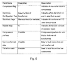
- a cache block can be represented by the fields shown in FIG. 6 .
- the compression algorithm for sub-blocks where a transform is not used could be FPC, or any other suitable algorithm.
- the compressed flag is one bit and indicates if the block is compressed or not. In the present example this bit does not need to be kept together with the rest of the compressed data. In a compressed cache, it can be kept together with the status bits. In compressed memory buses it can be transmitted as a header and for compressed main memory it can be kept in a meta-data structure. In the present example this bit is provided regardless of the chosen algorithm.
- the sub-block configuration tag field comprises log 2 (n) bits, where n is the number of transforms (i.e. the number of different sub-block configurations). It indicates which transform has been used.
- the sub-block flag field includes a sub-block flag for each sub-block identifying whether a compressed representation of a transform of a sub-block of uncompressed data or compressed representation of the sub-block of uncompressed data is used.
- the repeat flag field comprising repeat flags for each transformed word indicating whether stored data comprises repeated data.
- the prefixes field contains compression algorithm prefixes for sub-blocks that are not transformed.
- the first data field holds the data for sub-blocks that are not transformed.
- the second data field for data for sub-blocks that are transformed.
- An example compression unit 44 is operable to either read or receive one or more data blocks to be compressed.
- the example compression unit 44 is operable to apply different transformations to the block based on different sub-block configurations and to determine which sub-block configuration, if any, gives effective compression, and within a sub-block, to determine whether to apply a direct compression algorithm or a transformed compression algorithm.
- the compression unit 44 can be operable to apply k different sub-block configurations to determine which, if any provides effective compression and, if so which sub-block configuration provides the best compression.
- the data block comprises b bytes of data.
- a byte comprises 8 bits.
- a byte can comprise another number of bits.
- the compression unit 44 is operable to initially set a best transform indicator to be no transform, whereby, if during the process of applying the k different sub-block configurations no sub-block configuration is determined to provide effective compression with respect to the original uncompressed block size of b bytes, then no compression will be applied to the block.
- the compression unit 44 also sets a smallest size variable for a block to b bytes, that is the size of the original uncompressed block.
- the values of k, b and the best transform indicator can be stored in a register or in memory in the data compression unit 44 .
- the sub-block configurations can be chosen to include different numbers m of n byte words.
- each of the sub-block configurations for a respective transforms can include a different number of m*n bytes.
- the compression unit 44 is operable to apply each of the different sub-block configurations. This can be done serially as indicated by the pseudo code in FIG. 7 , or could be done in parallel, for example in separate hardware units, or using separate process threads processed in parallel. For ease of explanation only, the pseudo code of FIG. 7 will be explained as being processed by a single thread.
- the compression unit 44 is operable to set a size variable to zero, and then assign n and m according to the current transform.
- the compression unit 44 is operable to perform a set of operations.
- a matrix of m rows of n bytes is generated by selecting m times, the next n bytes.
- the matrix is transposed.
- a compressed representation of the transformed matrix is accumulated, wherein, for each of the n rows of the transformed matrix
- a compressed representation of the untransformed sub-block is generated.
- the size variable value is set to the previous size variable value plus the size of the compressed representation of the sub-block (temp).
- the compression unit 44 is operable to compare the size variable to the smallest size variable that was initially set to the size b of the uncompressed data block. If the size variable for the accumulated compressed representation of the sub-blocks for a given sub-block configuration is smaller that the size of the block of uncompressed data or of an accumulated compressed representation of all previously processed sub-block configurations, then the size variable will be smaller than the current value of the smallest size variable. In this case, accumulated compressed representation is buffered as a best compressed representation of the block and any previously buffered best compressed representation of the block is discarded, the best transform indicator is set to represent the current transform (i.e. the currently processed sub-block configuration) and the smallest size variable value is set to the current size variable value, otherwise the currently accumulated compressed representation of the block is discarded and the best transform indicator and the smallest size variable values are not changed.
- the best transform indicator After applying the k different sub-block configurations, if the best transform indicator is still set to the no-transform value, then it is determined that no sub-block configuration gave an effective compression of the block and the block is transferred in uncompressed format for storage or transmission as appropriate. Alternatively, if the best transform indicator is set to a value representing a particular transform (i.e., a particular sub-block configuration), then the accumulated compressed representation for that transform is transferred for storage or transmission as appropriate.
- FIG. 8 sets out pseudo code for an example decompression process as performed by an example decompression unit 42 .
- the decompression unit 42 can be operable serially as indicated by the pseudo code in FIG. 8 , or could be done, at least in part, in parallel, for example in separate hardware units, or using separate process threads processed in parallel.
- the pseudo code of FIG. 8 will be explained as being processed by a single thread.
- a decompression unit 42 is operable to receive or to read a block of compressed (potentially compressed) data.
- the compression unit is operable to determine for a particular block whether the data is compressed or not with reference to a compressed flag associated with the block of data as represented in FIG. 6 . If the compressed flag indicated that the block of data is not compressed, the block of data is transferred for storage or transmission as appropriate. Alternatively, if the compressed flag indicated that the block of data is compressed, then the block of data is processed further as set out in FIG. 8 .
- Values of n and m are assigned according to a block format indicated by the sub-block configuration tag associated with the block of data as illustrated in FIG. 6 .
- the decompression unit 42 is operable to process a sub-block of the data.
- each transformed row of the sub-block is processed. If a repeat flag is set for a transformed row of the sub-block, then the next byte is repeated m times for that transformed row. Alternatively, if the repeat flag is not set for a transformed row of the sub-block, then the next m bytes are used to define that transformed row. The n rows of the sub-block can then be transposed to generate the uncompressed sub-block of m rows of n bytes.
- a predetermined decompression algorithm e.g., FPC
- Each of the sub-blocks are processed to generate the original b bytes of uncompressed data.
- data comprising a variable number of data words, having different numbers of data groups, and arranged in different data block sizes can be manipulated according to the transform and compression/decompression methodologies described herein. Indeed, as described above, these variables can themselves be applied as parameters in the compression and decompression methodology.
- the number of bytes in a block of data to which the compression/decompression methodology are applied may be varied as a parameter.
- the block size could, for example, be set at 4 bytes, 32 bytes, 512 bytes, 8 kB or 1 MB.
- the block size can be chosen to correspond to a block size which is used in the memory of a computer system.
- the block size can correspond to the page size in a memory of a computer system, while in another particular example, the block size can correspond to a cache block size in the memory of the computer system.
- the data block can be split into 2, 4, 8, 64 or any other convenient number of data words.
- each data word can be split into any convenient number of groups, for example, 2 groups, 4 groups, 8 groups, 64 groups.
- the number of data groups in each data word does not place any constraints on the number of data words in each data block. While, in the example described above, the data block includes the same number of data words as there are data groups in each data word, this need not necessarily be the case.
- the consequence of having, for example, more data groups in each data word than there are data words in each data block is that when the data transform is applied to the uncompressed data, the resulting transformed data comprises more data words than there are data groups in each data word. Nevertheless, this need not inhibit or prevent the application of a data compression scheme such as FPC scheme to the transformed data words.
- block size, word number and data group numbers can be tailored to correspond to the characteristics of a computer system, they could also be varied to maximize compression. For example, compression can be applied using different block sizes, word numbers and data group numbers to select a compression type which is best.
- a tag can be added to compressed data, thereby to indicate whether the data has been compressed, and/or to indicate characteristics of the compression/decompression methodology which have been applied.
- the tag can be in the form of a binary prefix comprising a number of bits n, which indicates whether the data is compressed and the parameters for the compression which has been used.
- a null tag value such as “0” can indicate that the data is uncompressed.
- the signed bit s is always one bit while the number of bits which are used to encode c and f can be varied according to the degree of precision which is desired.
- the method of compressing can include compressing uncompressed data from a first level memory of a computer system and storing the compressed data in a second level memory of the computer system.
- references to a first level memory in this document does not mean a memory at a level one, rather that it relates to an nth level (n being an integer) of a plurality of memory levels.
- references to a second level memory in this document does not mean a memory at a level two, or a memory at a level necessarily adjacent to adjacent the first level, rather that it relates to an n+mth level (n and m being integers) of a plurality of memory levels.
- the first level memory could comprise a cache
- the plurality of data words in the uncompressed data could correspond to a cache line of data in the cache
- the second level memory could comprise a main memory and the method could comprise writing the transformed and compressed data to the main memory.
- the first level memory could comprise an L2 cache
- the second level memory could comprise an L3 cache
- the plurality of data words in the uncompressed data could correspond to a cache line of data in the L2 cache and the method could comprise writing the transformed and compressed data to the L3 cache.
- An example embodiment of the method of compressing can include compressing uncompressed data and transferring the compressed data words from a first location to a second location.
- An example of the method of compressing can include applying the transform and/or data compression scheme to uncompressed data comprising different sized data blocks, data words or data groups, wherein the transform and/or data compression scheme are applied to the different sized data words, data groups and/or data blocks in parallel.
- An example of the method of compressing can include applying the transform and/or data compression scheme to uncompressed data comprising different sized blocks, data words or data groups, and selecting a best transform and/or compression scheme to use according to the degree of compression which is achieved.
- An example of the method of decompressing can comprise applying the data decompression scheme and/or transform to produce different sized data blocks, data words or data groups, wherein the data decompression scheme and/or transform are applied to produce the different sized data blocks, data words or data groups in parallel.
- the invention could be implemented in hardware in a computer system.
- the invention may be implemented in software, in the form of a computer program product.
- the computer program product can be provided on a carrier medium.
- an embodiment can be implemented in hardware or firmware, other embodiment can provide a computer program product on a carrier medium, the program product including program instructions executable in a computer system to implement a method of compressing uncompressed data from a first level memory of a computer system for storage in a second level memory of the computer system.
- a computer program product can be in the form of a computer program, for example on a carrier medium.
- the carrier medium could be a storage medium, such as a solid state, magnetic, optical, magneto-optical or other storage medium.
- the carrier medium could be a transmission medium such as broadcast, telephonic, computer network, wired, wireless, electrical, electromagnetic, optical or indeed any other transmission medium.
Abstract
Description
-
- if the row consists of m repeated bytes, the row is replaced by the repeated byte and a repeated (transform) flag is set,
- otherwise the m bytes of the row are retained and the repeated (transform) flag is cleared.
-
- a compressed representation (temp) of the sub-block is set to be the compressed representation of the untransformed sub-block and a sub-block bit is cleared,
- otherwise the compressed representation (temp) of the sub-block is set to be the compressed representation of the transformed matrix and the sub-block bit is set.
f.p.n.=s×f×2c (1)
Claims (18)
Priority Applications (1)
| Application Number | Priority Date | Filing Date | Title |
|---|---|---|---|
| US12/059,393 US8208532B2 (en) | 2008-03-31 | 2008-03-31 | Method and apparatus for data compression and decompression |
Applications Claiming Priority (1)
| Application Number | Priority Date | Filing Date | Title |
|---|---|---|---|
| US12/059,393 US8208532B2 (en) | 2008-03-31 | 2008-03-31 | Method and apparatus for data compression and decompression |
Publications (2)
| Publication Number | Publication Date |
|---|---|
| US20090245382A1 US20090245382A1 (en) | 2009-10-01 |
| US8208532B2 true US8208532B2 (en) | 2012-06-26 |
Family
ID=41117164
Family Applications (1)
| Application Number | Title | Priority Date | Filing Date |
|---|---|---|---|
| US12/059,393 Active 2031-04-25 US8208532B2 (en) | 2008-03-31 | 2008-03-31 | Method and apparatus for data compression and decompression |
Country Status (1)
| Country | Link |
|---|---|
| US (1) | US8208532B2 (en) |
Cited By (3)
| Publication number | Priority date | Publication date | Assignee | Title |
|---|---|---|---|---|
| US20130003828A1 (en) * | 2011-07-01 | 2013-01-03 | Cohen Robert A | Method for Selecting Transform Types From Mapping Table for Prediction Modes |
| US9634689B2 (en) | 2014-08-20 | 2017-04-25 | Sunedison Semiconductor Limited (Uen201334164H) | Method and system for arranging numeric data for compression |
| US10305508B2 (en) * | 2018-05-11 | 2019-05-28 | Intel Corporation | System for compressing floating point data |
Families Citing this family (11)
| Publication number | Priority date | Publication date | Assignee | Title |
|---|---|---|---|---|
| KR20100095992A (en) * | 2009-02-23 | 2010-09-01 | 한국과학기술원 | Method for encoding partitioned block in video encoding, method for decoding partitioned block in video decoding and recording medium implementing the same |
| US8588227B2 (en) * | 2009-07-17 | 2013-11-19 | Qualcomm Incorporated | Recursive header compression for relay nodes |
| KR101438471B1 (en) * | 2011-01-03 | 2014-09-16 | 미디어텍 인크. | Method of filter-unit based in-loop filtering |
| US9378560B2 (en) * | 2011-06-17 | 2016-06-28 | Advanced Micro Devices, Inc. | Real time on-chip texture decompression using shader processors |
| US9325762B2 (en) | 2012-12-11 | 2016-04-26 | Qualcomm Incorporated | Method and apparatus for efficient signaling for compression |
| US9350676B2 (en) | 2012-12-11 | 2016-05-24 | Qualcomm Incorporated | Method and apparatus for classifying flows for compression |
| US9292449B2 (en) * | 2013-12-20 | 2016-03-22 | Intel Corporation | Cache memory data compression and decompression |
| KR20240001326A (en) | 2015-05-21 | 2024-01-03 | 제로포인트 테크놀로지 에이비 | Methods, Devices and Systems for semantic-value data compression and decompression |
| CA2986555A1 (en) | 2015-05-21 | 2016-11-24 | Zeropoint Technologies Ab | Methods, devices and systems for hybrid data compression and decompression |
| SE540178C2 (en) | 2016-01-29 | 2018-04-24 | Zeropoint Tech Ab | Methods, devices and systems for compressing and decompressing data |
| US10334334B2 (en) * | 2016-07-22 | 2019-06-25 | Intel Corporation | Storage sled and techniques for a data center |
Citations (7)
| Publication number | Priority date | Publication date | Assignee | Title |
|---|---|---|---|---|
| US5467087A (en) * | 1992-12-18 | 1995-11-14 | Apple Computer, Inc. | High speed lossless data compression system |
| US6075470A (en) * | 1998-02-26 | 2000-06-13 | Research In Motion Limited | Block-wise adaptive statistical data compressor |
| US6253264B1 (en) * | 1997-03-07 | 2001-06-26 | Intelligent Compression Technologies | Coding network grouping data of same data type into blocks using file data structure and selecting compression for individual block base on block data type |
| US7130913B2 (en) * | 1999-03-11 | 2006-10-31 | Realtime Data Llc | System and methods for accelerated data storage and retrieval |
| US7161506B2 (en) * | 1998-12-11 | 2007-01-09 | Realtime Data Llc | Systems and methods for data compression such as content dependent data compression |
| US7492290B1 (en) * | 2007-08-15 | 2009-02-17 | Red Hat, Inc. | Alternative encoding for LZSS output |
| US7564861B1 (en) * | 2002-08-22 | 2009-07-21 | 3Com Corporation | Systems and methods for compressing data |
-
2008
- 2008-03-31 US US12/059,393 patent/US8208532B2/en active Active
Patent Citations (7)
| Publication number | Priority date | Publication date | Assignee | Title |
|---|---|---|---|---|
| US5467087A (en) * | 1992-12-18 | 1995-11-14 | Apple Computer, Inc. | High speed lossless data compression system |
| US6253264B1 (en) * | 1997-03-07 | 2001-06-26 | Intelligent Compression Technologies | Coding network grouping data of same data type into blocks using file data structure and selecting compression for individual block base on block data type |
| US6075470A (en) * | 1998-02-26 | 2000-06-13 | Research In Motion Limited | Block-wise adaptive statistical data compressor |
| US7161506B2 (en) * | 1998-12-11 | 2007-01-09 | Realtime Data Llc | Systems and methods for data compression such as content dependent data compression |
| US7130913B2 (en) * | 1999-03-11 | 2006-10-31 | Realtime Data Llc | System and methods for accelerated data storage and retrieval |
| US7564861B1 (en) * | 2002-08-22 | 2009-07-21 | 3Com Corporation | Systems and methods for compressing data |
| US7492290B1 (en) * | 2007-08-15 | 2009-02-17 | Red Hat, Inc. | Alternative encoding for LZSS output |
Non-Patent Citations (8)
| Title |
|---|
| Abali et al., "Performance of Hardware Compressed Main Memory", High-Performance Computer Architecture, HPCA, The Seventh International Symposium on High-Performance Computer Architecture, Jan. 2001, pp. 73-81. |
| Alameldeen et al., "Adaptive Cache Compression for High-Performance Processors", 31st Annual International Symposium on Computer Architecture, Munich, Germany Jun. 19-23, 2004, pp. 1-12. |
| Alameldeen et al., "Frequent Pattern Compression: A Significance-Based Compression Scheme for L2 Caches", Technical Report 1500, Computer Sciences Dept., UW-Madison, Apr. 2004, pp. 1-14. |
| Burrows et al., "A Block-Sorting Lossless Data Compression Algorithm", SRC Research Report, Systems Research Center, 130 Lytton Avenue, Palo Alto, CA 94301, May 10, 1994, pp. 1-24. |
| Storer et al., "Data Compression Via Textual Substitution", Journal of the Association for Computing Machinery, vol. 29, No. 4, Oct. 1982, pp. 928-951. |
| Tremaine et al., "IBM Memory Expansion Technology (MXT)", IBM J. Res. & Dev., vol. 45, No. 2, Mar. 2001, pp. 271-285. |
| Tremaine et al., "Pinnacle: IBM MXT in a Memory Controller Chip", IEEE, vol. 21, Issue 2, Mar./Apr. 2001, pp. 56-68. |
| Ziv et al. "A Universal Algorithm for Sequential Data Compression", IEEE Transactions on Information Theory, vol. IT-23, No. 3, May 1977, pp. 337-343. |
Cited By (4)
| Publication number | Priority date | Publication date | Assignee | Title |
|---|---|---|---|---|
| US20130003828A1 (en) * | 2011-07-01 | 2013-01-03 | Cohen Robert A | Method for Selecting Transform Types From Mapping Table for Prediction Modes |
| US8929455B2 (en) * | 2011-07-01 | 2015-01-06 | Mitsubishi Electric Research Laboratories, Inc. | Method for selecting transform types from mapping table for prediction modes |
| US9634689B2 (en) | 2014-08-20 | 2017-04-25 | Sunedison Semiconductor Limited (Uen201334164H) | Method and system for arranging numeric data for compression |
| US10305508B2 (en) * | 2018-05-11 | 2019-05-28 | Intel Corporation | System for compressing floating point data |
Also Published As
| Publication number | Publication date |
|---|---|
| US20090245382A1 (en) | 2009-10-01 |
Similar Documents
| Publication | Publication Date | Title |
|---|---|---|
| US8208532B2 (en) | Method and apparatus for data compression and decompression | |
| US7447814B1 (en) | Method and apparatus for fast loss-less memory data compression wherein data corresponds to a cache line of data in cache | |
| US8988257B2 (en) | Data compression utilizing variable and limited length codes | |
| JP3009727B2 (en) | Improved data compression device | |
| US5175543A (en) | Dictionary reset performance enhancement for data compression applications | |
| CN107836083B (en) | Method, apparatus and system for semantic value data compression and decompression | |
| US8407378B2 (en) | High-speed inline data compression inline with an eight byte data path | |
| US6744388B1 (en) | Hardware-friendly general purpose data compression/decompression algorithm | |
| US9094039B2 (en) | Efficient deflate decompression | |
| JP2004334846A (en) | Method and system for minimizing length of defect list of storage device | |
| CN111294053B (en) | Hardware-friendly data compression method, system and device | |
| US5886655A (en) | Arithmetic coding context model that accelerates adaptation for small amounts of data | |
| CN112953550A (en) | Data compression method, electronic device and storage medium | |
| US11955995B2 (en) | Apparatus and method for two-stage lossless data compression, and two-stage lossless data decompression | |
| US6247015B1 (en) | Method and system for compressing files utilizing a dictionary array | |
| US9137336B1 (en) | Data compression techniques | |
| CN110943744A (en) | Data compression, decompression and processing method and device based on data compression and decompression | |
| Funasaka et al. | Adaptive loss‐less data compression method optimized for GPU decompression | |
| EP2462696A1 (en) | Compression of bitmaps and values | |
| US10601442B2 (en) | Memory compression method and apparatus | |
| JP2968112B2 (en) | Code conversion method | |
| CN110209598B (en) | Cache memory, data read-write control method and system | |
| CN114222973A (en) | Decompression engine for decompressing compressed input data comprising multiple data streams | |
| JPH03204234A (en) | Restoration of compressed data | |
| US5880688A (en) | Arithmetic coding context model that adapts to the amount of data |
Legal Events
| Date | Code | Title | Description |
|---|---|---|---|
| AS | Assignment |
Owner name: SUN MICROSYSTEMS, INC., CALIFORNIA Free format text: ASSIGNMENT OF ASSIGNORS INTEREST;ASSIGNOR:EKMAN, MAGNUS;REEL/FRAME:020881/0292 Effective date: 20080325 |
|
| FEPP | Fee payment procedure |
Free format text: PAYER NUMBER DE-ASSIGNED (ORIGINAL EVENT CODE: RMPN); ENTITY STATUS OF PATENT OWNER: LARGE ENTITY Free format text: PAYOR NUMBER ASSIGNED (ORIGINAL EVENT CODE: ASPN); ENTITY STATUS OF PATENT OWNER: LARGE ENTITY |
|
| STCF | Information on status: patent grant |
Free format text: PATENTED CASE |
|
| FPAY | Fee payment |
Year of fee payment: 4 |
|
| AS | Assignment |
Owner name: ORACLE AMERICA, INC., CALIFORNIA Free format text: MERGER AND CHANGE OF NAME;ASSIGNORS:ORACLE USA, INC.;SUN MICROSYSTEMS, INC.;ORACLE AMERICA, INC.;REEL/FRAME:037311/0171 Effective date: 20100212 |
|
| MAFP | Maintenance fee payment |
Free format text: PAYMENT OF MAINTENANCE FEE, 8TH YEAR, LARGE ENTITY (ORIGINAL EVENT CODE: M1552); ENTITY STATUS OF PATENT OWNER: LARGE ENTITY Year of fee payment: 8 |
|
| MAFP | Maintenance fee payment |
Free format text: PAYMENT OF MAINTENANCE FEE, 12TH YEAR, LARGE ENTITY (ORIGINAL EVENT CODE: M1553); ENTITY STATUS OF PATENT OWNER: LARGE ENTITY Year of fee payment: 12 |