US8207728B2 - Integrated power and communication device - Google Patents
Integrated power and communication device Download PDFInfo
- Publication number
- US8207728B2 US8207728B2 US11/345,932 US34593206A US8207728B2 US 8207728 B2 US8207728 B2 US 8207728B2 US 34593206 A US34593206 A US 34593206A US 8207728 B2 US8207728 B2 US 8207728B2
- Authority
- US
- United States
- Prior art keywords
- power distribution
- control device
- wireless communication
- pole
- communication device
- Prior art date
- Legal status (The legal status is an assumption and is not a legal conclusion. Google has not performed a legal analysis and makes no representation as to the accuracy of the status listed.)
- Active, expires
Links
- 239000004020 conductor Substances 0.000 claims abstract description 12
- 239000012212 insulator Substances 0.000 claims description 18
- 239000003990 capacitor Substances 0.000 claims description 7
- 230000008878 coupling Effects 0.000 claims description 3
- 238000010168 coupling process Methods 0.000 claims description 3
- 238000005859 coupling reaction Methods 0.000 claims description 3
- 230000001143 conditioned effect Effects 0.000 abstract description 2
- 239000000463 material Substances 0.000 description 5
- 238000013480 data collection Methods 0.000 description 3
- 238000012544 monitoring process Methods 0.000 description 3
- 230000005540 biological transmission Effects 0.000 description 2
- 238000010586 diagram Methods 0.000 description 2
- 230000006870 function Effects 0.000 description 2
- 238000011179 visual inspection Methods 0.000 description 2
- 239000004593 Epoxy Substances 0.000 description 1
- 150000001875 compounds Chemical class 0.000 description 1
- 230000003750 conditioning effect Effects 0.000 description 1
- 238000001514 detection method Methods 0.000 description 1
- 230000036039 immunity Effects 0.000 description 1
- 238000009434 installation Methods 0.000 description 1
- 229920001296 polysiloxane Polymers 0.000 description 1
- 238000004382 potting Methods 0.000 description 1
- 238000001228 spectrum Methods 0.000 description 1
Images


Classifications
-
- G—PHYSICS
- G08—SIGNALLING
- G08C—TRANSMISSION SYSTEMS FOR MEASURED VALUES, CONTROL OR SIMILAR SIGNALS
- G08C17/00—Arrangements for transmitting signals characterised by the use of a wireless electrical link
- G08C17/02—Arrangements for transmitting signals characterised by the use of a wireless electrical link using a radio link
-
- H—ELECTRICITY
- H02—GENERATION; CONVERSION OR DISTRIBUTION OF ELECTRIC POWER
- H02J—CIRCUIT ARRANGEMENTS OR SYSTEMS FOR SUPPLYING OR DISTRIBUTING ELECTRIC POWER; SYSTEMS FOR STORING ELECTRIC ENERGY
- H02J5/00—Circuit arrangements for transfer of electric power between ac networks and dc networks
-
- H—ELECTRICITY
- H02—GENERATION; CONVERSION OR DISTRIBUTION OF ELECTRIC POWER
- H02J—CIRCUIT ARRANGEMENTS OR SYSTEMS FOR SUPPLYING OR DISTRIBUTING ELECTRIC POWER; SYSTEMS FOR STORING ELECTRIC ENERGY
- H02J7/00—Circuit arrangements for charging or depolarising batteries or for supplying loads from batteries
- H02J7/02—Circuit arrangements for charging or depolarising batteries or for supplying loads from batteries for charging batteries from ac mains by converters
-
- H—ELECTRICITY
- H04—ELECTRIC COMMUNICATION TECHNIQUE
- H04L—TRANSMISSION OF DIGITAL INFORMATION, e.g. TELEGRAPHIC COMMUNICATION
- H04L12/00—Data switching networks
- H04L12/02—Details
- H04L12/10—Current supply arrangements
-
- H—ELECTRICITY
- H04—ELECTRIC COMMUNICATION TECHNIQUE
- H04L—TRANSMISSION OF DIGITAL INFORMATION, e.g. TELEGRAPHIC COMMUNICATION
- H04L43/00—Arrangements for monitoring or testing data switching networks
- H04L43/08—Monitoring or testing based on specific metrics, e.g. QoS, energy consumption or environmental parameters
- H04L43/0805—Monitoring or testing based on specific metrics, e.g. QoS, energy consumption or environmental parameters by checking availability
- H04L43/0817—Monitoring or testing based on specific metrics, e.g. QoS, energy consumption or environmental parameters by checking availability by checking functioning
-
- H—ELECTRICITY
- H04—ELECTRIC COMMUNICATION TECHNIQUE
- H04W—WIRELESS COMMUNICATION NETWORKS
- H04W88/00—Devices specially adapted for wireless communication networks, e.g. terminals, base stations or access point devices
- H04W88/08—Access point devices
-
- Y—GENERAL TAGGING OF NEW TECHNOLOGICAL DEVELOPMENTS; GENERAL TAGGING OF CROSS-SECTIONAL TECHNOLOGIES SPANNING OVER SEVERAL SECTIONS OF THE IPC; TECHNICAL SUBJECTS COVERED BY FORMER USPC CROSS-REFERENCE ART COLLECTIONS [XRACs] AND DIGESTS
- Y02—TECHNOLOGIES OR APPLICATIONS FOR MITIGATION OR ADAPTATION AGAINST CLIMATE CHANGE
- Y02A—TECHNOLOGIES FOR ADAPTATION TO CLIMATE CHANGE
- Y02A30/00—Adapting or protecting infrastructure or their operation
-
- Y—GENERAL TAGGING OF NEW TECHNOLOGICAL DEVELOPMENTS; GENERAL TAGGING OF CROSS-SECTIONAL TECHNOLOGIES SPANNING OVER SEVERAL SECTIONS OF THE IPC; TECHNICAL SUBJECTS COVERED BY FORMER USPC CROSS-REFERENCE ART COLLECTIONS [XRACs] AND DIGESTS
- Y02—TECHNOLOGIES OR APPLICATIONS FOR MITIGATION OR ADAPTATION AGAINST CLIMATE CHANGE
- Y02B—CLIMATE CHANGE MITIGATION TECHNOLOGIES RELATED TO BUILDINGS, e.g. HOUSING, HOUSE APPLIANCES OR RELATED END-USER APPLICATIONS
- Y02B70/00—Technologies for an efficient end-user side electric power management and consumption
- Y02B70/30—Systems integrating technologies related to power network operation and communication or information technologies for improving the carbon footprint of the management of residential or tertiary loads, i.e. smart grids as climate change mitigation technology in the buildings sector, including also the last stages of power distribution and the control, monitoring or operating management systems at local level
-
- Y—GENERAL TAGGING OF NEW TECHNOLOGICAL DEVELOPMENTS; GENERAL TAGGING OF CROSS-SECTIONAL TECHNOLOGIES SPANNING OVER SEVERAL SECTIONS OF THE IPC; TECHNICAL SUBJECTS COVERED BY FORMER USPC CROSS-REFERENCE ART COLLECTIONS [XRACs] AND DIGESTS
- Y02—TECHNOLOGIES OR APPLICATIONS FOR MITIGATION OR ADAPTATION AGAINST CLIMATE CHANGE
- Y02D—CLIMATE CHANGE MITIGATION TECHNOLOGIES IN INFORMATION AND COMMUNICATION TECHNOLOGIES [ICT], I.E. INFORMATION AND COMMUNICATION TECHNOLOGIES AIMING AT THE REDUCTION OF THEIR OWN ENERGY USE
- Y02D30/00—Reducing energy consumption in communication networks
- Y02D30/70—Reducing energy consumption in communication networks in wireless communication networks
-
- Y—GENERAL TAGGING OF NEW TECHNOLOGICAL DEVELOPMENTS; GENERAL TAGGING OF CROSS-SECTIONAL TECHNOLOGIES SPANNING OVER SEVERAL SECTIONS OF THE IPC; TECHNICAL SUBJECTS COVERED BY FORMER USPC CROSS-REFERENCE ART COLLECTIONS [XRACs] AND DIGESTS
- Y04—INFORMATION OR COMMUNICATION TECHNOLOGIES HAVING AN IMPACT ON OTHER TECHNOLOGY AREAS
- Y04S—SYSTEMS INTEGRATING TECHNOLOGIES RELATED TO POWER NETWORK OPERATION, COMMUNICATION OR INFORMATION TECHNOLOGIES FOR IMPROVING THE ELECTRICAL POWER GENERATION, TRANSMISSION, DISTRIBUTION, MANAGEMENT OR USAGE, i.e. SMART GRIDS
- Y04S20/00—Management or operation of end-user stationary applications or the last stages of power distribution; Controlling, monitoring or operating thereof
- Y04S20/20—End-user application control systems
-
- Y—GENERAL TAGGING OF NEW TECHNOLOGICAL DEVELOPMENTS; GENERAL TAGGING OF CROSS-SECTIONAL TECHNOLOGIES SPANNING OVER SEVERAL SECTIONS OF THE IPC; TECHNICAL SUBJECTS COVERED BY FORMER USPC CROSS-REFERENCE ART COLLECTIONS [XRACs] AND DIGESTS
- Y04—INFORMATION OR COMMUNICATION TECHNOLOGIES HAVING AN IMPACT ON OTHER TECHNOLOGY AREAS
- Y04S—SYSTEMS INTEGRATING TECHNOLOGIES RELATED TO POWER NETWORK OPERATION, COMMUNICATION OR INFORMATION TECHNOLOGIES FOR IMPROVING THE ELECTRICAL POWER GENERATION, TRANSMISSION, DISTRIBUTION, MANAGEMENT OR USAGE, i.e. SMART GRIDS
- Y04S40/00—Systems for electrical power generation, transmission, distribution or end-user application management characterised by the use of communication or information technologies, or communication or information technology specific aspects supporting them
Definitions
- This patent relates to power distribution system sensor or control devices, and more particularly, this patent relates to a power distribution system sensor and/or control device integrated with a communication device, such as a wireless communication device.
- Wired or wireless communication capability with remote sensing and data collection can eliminate or at least alleviate the requirement for visual inspection and provide real time system condition data.
- the remote sensing and data collection devices with wireless communication capability can be arranged such that the wireless communication components act as repeaters. This arrangement permits the wireless transceiver components to operate over large distances as a distributed radio network using relatively low transmit power.
- Remote data collection and wireless reporting devices require a weather resistant and electrically insulated (e.g., to isolate electromagnetic interference) enclosure for the sensing and communication components, which add considerably to the cost of the device. Additionally, there is required a power source, e.g., a 120 volt alternating current (120 vac) power source, to supply power to the components disposed within the enclosure.
- a power source e.g., a 120 volt alternating current (120 vac) power source
- FIG. 1 is a graphic illustration of a power and communication device in accordance with a preferred embodiment of the invention.
- FIG. 2 is a block diagram of power and communication components that may be incorporated into the power and communication device illustrated in FIG. 1 .
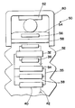
- FIG. 3 is an illustration of a power and communication device in accordance with an alternate preferred embodiment of the invention.
- a power distribution system sensor and/or control device is integrated with a wireless communication device in an enclosing weather resistant housing.
- the device includes a power supply that is adapted to couple to a conductor of the power distribution network to provide rectified and conditioned power as necessary to operate the distribution and/or control device and the wireless transceiver.
- the wireless communication device may be a low power packet data radio transceiver operating in accordance with any suitable communication standard, including asynchronous packet data communication in the 902-928 MHz band, IEEE 802.11a, 802.11b or 802.11n compliant communications in the 2.4 GHz band, or any other suitable wireless data communication standard.
- the wireless communication device may further act as a repeater, receiving and retransmitting signals received from other wireless communication devices, and as such, operate as part of a distributed radio network.
- the wireless communication device itself, or by coupling via the distributed radio network, can act as an Internet access point.
- the sensor and/or control device may be any device that provides data indicative of its own operation, an operating characteristic of the power distribution system or both.
- the sensor and/or control device may be a voltage sensor, a current sensor, a voltage and current sensor or a fault detector each of which provide an indication of one or more operating characteristics of the power distribution system.
- the sensor and/or control device may also be a switch, a switch control, a fuse and an interrupter each of which includes a data output indicative of the state of the device.
- the sensor and/or control device may be a combination of such sensor and operating devices. It will be appreciated that the foregoing list of devices is exemplary and virtually any sensor and/or control device may be incorporated into the device.
- a current carrying conductor or line 12 is suspended between a plurality of poles 14 .
- a power distribution system sensor and/or control device 16 (the device 16 ) is supported on the poles 14 by a suitable bracket 18 .
- the device 16 is coupled to the line 12 by a conductor 20 .
- the line 12 need not be suspended by poles, but could be a buried conductor.
- the device 16 may then be suitably mounted and coupled to the buried line.
- Typical installations will see several devices 16 secured to poles 14 and coupled to the line 12 .
- the devices 16 need not be installed on adjacent poles or to the single line 12 , but may be instead installed as necessary in a distributed manner throughout the power distribution system 10 .
- the devices 16 may communicate with each other and/or with a base station 22 by radio transmissions 21 .
- the base station 22 may be part of a centralized control/monitoring facility for the power distribution system 10 .
- the base station 22 may be coupled to a communication network 24 , such as the Internet, to which a control/monitoring facility for the power distribution system may be coupled.
- each of the devices 16 may act as an Internet access point such that a field technician may utilize the device 16 to access either the Internet generally or to link particularly to the power distribution system centralized control/monitoring facility via the Internet.
- FIG. 2 illustrates the device 16 in functional block diagram form.
- the device 16 includes a weather resistant housing 24 that may be formed to include shielding 26 for shielding the electrical components of the device 16 disposed within the housing 24 from electromagnetic and other forms of noise and interference.
- the housing 24 is preferably molded from a weather resistant, electrically insulating epoxy material, such as the Cypoxy® material available from S & C Electric Co., Chicago, Ill.
- the electrical components of the device 16 may be molded into and/or encapsulated within the Cypoxy material providing a secure, weather resistant yet low cost enclosure.
- the electrical components include a power supply 28 .
- the power supply 28 may capacitively couple to the line 12 or may otherwise couple to the line 12 to extract power from the line 12 .
- the power supply 28 may therefore includes a current transformer 30 .
- the current transformer 30 is coupled to ground 34 as is the shielding 26 .
- the transformer 30 is coupled to rectifying and conditioning circuitry 32 that is further coupled to a storage device 36 that is therefore coupled to and charged by the power supply 28 .
- the storage device 36 may be a battery, such as a wet or gel cell battery.
- the storage device 36 may be a capacitor or capacitor bank ( FIG. 2 illustrates a capacitor bank including three capacitors 38 , although fewer or more capacitors may be used).
- the storage device 36 is configured to store sufficient power to allow the device 16 to operate through an extended outage period wherein electrical current is not conducted on the line 12 .
- the device 16 includes a processor 34 including a memory (not depicted) containing a control program that directs the operation of the processor 34 for controlling the operation of the device 16 .
- a data producing/collecting sensor and/or control device 38 that provides data indicative of its own operation, an operating characteristic of the power distribution system or both or alternatively collects data, e.g. a memory or buffer, from sensors, actuators or such devices (not separately depicted) is communicatively coupled to the processor 34 , for example by a bus 35 .
- the sensor and/or control device 38 may be a voltage sensor, a current sensor, a voltage and current sensor or a fault detector each of which provide an indication of one or more operating characteristics of the power distribution system.
- the sensor and/or control device 38 may also be a switch, a switch control, a fuse and an interrupter each of which includes a data output indicative of the state of the device. It will be appreciated that the list of devices is exemplary and virtually any sensor and/or control device may be incorporated into the device 16 .
- the sensor and/or control device 38 communicates its data and/or the collected data to a wireless transceiver 40 , which is also communicatively coupled to the processor 34 .
- the wireless transceiver 40 is coupled to an antenna 42 .
- the antenna 42 is shown external to the housing 24 ; however, it will be appreciated that the antenna 42 may be internal to the housing 24 or incorporated into the housing 24 . For example, the antenna 42 may be molded into the housing 24 .
- the wireless transceiver 40 may be a packet radio, i.e., a transceiver capable of communicating discrete data packets in accordance with a suitable communication protocol.
- the transceiver 40 may communicate using an asynchronous, spread spectrum communication protocol, such as that employed by the Utilinet® radios and networks of radios available from S & C.
- Other standards such as the IEEE 802.11a, 802.11b and/or 802.11n standards, or any other suitable, low power data communication standard may be employed, however.
- the device 16 may be configured and hard coded with an identification by which it identified to the base station 22 and within the distributed radio network so that communications are directed to it and its communications are identified when transmitted.
- the processor 34 may perform an initialization routine whereby the device 16 requests and is assigned an identification, such as a dynamic Internet Protocol (IP) address assignment. The identification is then used to send and receive data from the device.
- IP Internet Protocol
- power is capacitively coupled from the line 12 to the power supply 28 , which operates to rectify and condition the power such that it is suitable to power the processor 34 , the sensor and/or control device 38 and the wireless transceiver 40 .
- the transceiver 40 As data is collected by the device 38 it is communicated to the transceiver 40 for transmission to adjacent devices 16 and/or to the base station 22 .
- the device 16 is advantageously self-powered and thus does not require a separate power supply.
- the electrical components of the device 16 may be encapsulated in the housing 24 . In this regard, the device 16 is made secure and weather resistant yet remains low cost.
- FIG. 3 illustrates an alternate embodiment of the integrated power and control device of the present invention.
- the integrated power and control device 50 is formed as a pole-line insulator. That is, the device 50 includes an insulating body/housing 52 configured as a pole-line insulator having a configuration for such purpose as is well known in the art.
- the electrical components of the integrated power and control device 50 are encapsulated within the housing 52 . The components may be preassembled and cast into the housing 52 . Alternatively, the housing 52 may be formed to include a cavity into which the electrical components are disposed. The components may be then secured and sealed within the housing 52 using silicone potting compound or any other suitable material.
- the line 12 is disposed on a top surface 54 of the housing 52 adjacent a coil 56 encircling a permeable core 58 for coupling power from the line 12 into the device 50 .
- the coil 56 thereby acts as the secondary coil of a transformer, such as the transformer 30 .
- the device 50 may further include a yoke 60 encircling and securing the line 12 to the housing 52 .
- the yoke 60 itself may be made of a permeable material and may be coupled to the permeable core 58 such that the core 58 and the yoke 60 fully encircle the line 12 .
- An insulator 62 may be provided between the line 12 and the yoke 60 to both insulate the line 12 from the yoke 60 as well as to facilitate dielectric stress relief.
- the invention has been described in terms of several embodiments, including a number of features and functions. Not all features and functions are required for every embodiment of the invention, and in this manner the invention provides a flexible, easily installed without breaking the conductor current sensor that has better noise immunity.
- the features discussed herein are intended to be illustrative of those features that may be implemented; however, such features should not be considered exhaustive of all possible features that may be implemented in a device configured in accordance with the embodiments of the invention.
- the herein described embodiments are illustrative, not limiting of the invention. The invention is defined and limited only by the following claims.
Landscapes
- Engineering & Computer Science (AREA)
- Computer Networks & Wireless Communication (AREA)
- Signal Processing (AREA)
- Environmental & Geological Engineering (AREA)
- Physics & Mathematics (AREA)
- General Physics & Mathematics (AREA)
- Power Engineering (AREA)
- Cable Transmission Systems, Equalization Of Radio And Reduction Of Echo (AREA)
- Remote Monitoring And Control Of Power-Distribution Networks (AREA)
Abstract
Description
Claims (15)
Priority Applications (1)
| Application Number | Priority Date | Filing Date | Title |
|---|---|---|---|
| US11/345,932 US8207728B2 (en) | 2005-02-28 | 2006-02-01 | Integrated power and communication device |
Applications Claiming Priority (2)
| Application Number | Priority Date | Filing Date | Title |
|---|---|---|---|
| US65625905P | 2005-02-28 | 2005-02-28 | |
| US11/345,932 US8207728B2 (en) | 2005-02-28 | 2006-02-01 | Integrated power and communication device |
Publications (2)
| Publication Number | Publication Date |
|---|---|
| US20060217058A1 US20060217058A1 (en) | 2006-09-28 |
| US8207728B2 true US8207728B2 (en) | 2012-06-26 |
Family
ID=36938951
Family Applications (1)
| Application Number | Title | Priority Date | Filing Date |
|---|---|---|---|
| US11/345,932 Active 2029-12-09 US8207728B2 (en) | 2005-02-28 | 2006-02-01 | Integrated power and communication device |
Country Status (2)
| Country | Link |
|---|---|
| US (1) | US8207728B2 (en) |
| CA (1) | CA2534937C (en) |
Cited By (1)
| Publication number | Priority date | Publication date | Assignee | Title |
|---|---|---|---|---|
| US20120255920A1 (en) * | 2011-04-11 | 2012-10-11 | Abb Technology Ag | Electrical equipment mounting frame |
Families Citing this family (13)
| Publication number | Priority date | Publication date | Assignee | Title |
|---|---|---|---|---|
| US6998962B2 (en) * | 2000-04-14 | 2006-02-14 | Current Technologies, Llc | Power line communication apparatus and method of using the same |
| US7626497B2 (en) | 2005-05-25 | 2009-12-01 | Current Technologies, Llc | Power line communication vegetation management system and method |
| US7468657B2 (en) * | 2006-01-30 | 2008-12-23 | Current Technologies, Llc | System and method for detecting noise source in a power line communications system |
| US7795877B2 (en) * | 2006-11-02 | 2010-09-14 | Current Technologies, Llc | Power line communication and power distribution parameter measurement system and method |
| US7714592B2 (en) * | 2007-11-07 | 2010-05-11 | Current Technologies, Llc | System and method for determining the impedance of a medium voltage power line |
| US20090289637A1 (en) * | 2007-11-07 | 2009-11-26 | Radtke William O | System and Method for Determining the Impedance of a Medium Voltage Power Line |
| US7965195B2 (en) * | 2008-01-20 | 2011-06-21 | Current Technologies, Llc | System, device and method for providing power outage and restoration notification |
| US8566046B2 (en) * | 2008-01-21 | 2013-10-22 | Current Technologies, Llc | System, device and method for determining power line equipment degradation |
| US20100070100A1 (en) * | 2008-09-15 | 2010-03-18 | Finlinson Jan F | Control architecture and system for wireless sensing |
| US8780537B2 (en) | 2010-05-07 | 2014-07-15 | Tyco Electronics Corporation | Integrated connection system for an electronic device |
| US10186912B2 (en) * | 2013-09-13 | 2019-01-22 | Qualcomm Incorporated | Pickup coil design for tight spaces and asymmetrical coupling |
| US10720781B2 (en) | 2017-10-16 | 2020-07-21 | Ardent Edge, LLC | Switching protection system |
| US12087523B2 (en) | 2020-12-07 | 2024-09-10 | G & W Electric Company | Solid dielectric insulated switchgear |
Citations (2)
| Publication number | Priority date | Publication date | Assignee | Title |
|---|---|---|---|---|
| US4286213A (en) * | 1979-03-19 | 1981-08-25 | Research Products Corporation | Energy sensor |
| US7282944B2 (en) * | 2003-07-25 | 2007-10-16 | Power Measurement, Ltd. | Body capacitance electric field powered device for high voltage lines |
-
2006
- 2006-02-01 US US11/345,932 patent/US8207728B2/en active Active
- 2006-02-01 CA CA 2534937 patent/CA2534937C/en active Active
Patent Citations (2)
| Publication number | Priority date | Publication date | Assignee | Title |
|---|---|---|---|---|
| US4286213A (en) * | 1979-03-19 | 1981-08-25 | Research Products Corporation | Energy sensor |
| US7282944B2 (en) * | 2003-07-25 | 2007-10-16 | Power Measurement, Ltd. | Body capacitance electric field powered device for high voltage lines |
Cited By (2)
| Publication number | Priority date | Publication date | Assignee | Title |
|---|---|---|---|---|
| US20120255920A1 (en) * | 2011-04-11 | 2012-10-11 | Abb Technology Ag | Electrical equipment mounting frame |
| US8919584B2 (en) * | 2011-04-11 | 2014-12-30 | Abb Technology Ag | Electrical equipment mounting frame |
Also Published As
| Publication number | Publication date |
|---|---|
| CA2534937A1 (en) | 2006-08-28 |
| US20060217058A1 (en) | 2006-09-28 |
| CA2534937C (en) | 2015-04-14 |
Similar Documents
| Publication | Publication Date | Title |
|---|---|---|
| US8207728B2 (en) | Integrated power and communication device | |
| KR101192015B1 (en) | Overhead power transmission and distribution line monitoring apparatus for selectively switching communication scheme of low loss directional antennas | |
| US6081729A (en) | Encapsulated tubular conductor | |
| US6980090B2 (en) | Device and method for coupling with electrical distribution network infrastructure to provide communications | |
| US9581624B2 (en) | Corona avoidance electric power line monitoring, communication and response system | |
| US20040083066A1 (en) | Electrical power metering system | |
| CN109599940A (en) | A kind of distribution transforming status remote monitoring system and method based on LPWAN | |
| TW200618018A (en) | Wireless communication fuse state indicator system and method | |
| CN202693740U (en) | GIS (Geographic Information System) partial discharge online monitoring comprehensive processing unit | |
| KR20170037320A (en) | Wired and wireless communication interface for automatic meter reading and system comprising the same | |
| CN104412179A (en) | Electrical combiner box with improved functionality | |
| CN105182074B (en) | Intelligent grid network unifies phasing system | |
| JP6721008B2 (en) | Air conditioner communication system and air conditioner | |
| CN110187248A (en) | A kind of open type substation wide area partial discharge monitoring internet of things sensors and its monitoring method | |
| US20060202820A1 (en) | Wireless Temperature and Pressure Sensor for High Voltage Applications | |
| CN217845422U (en) | Temperature monitoring device suitable for strong alternating electromagnetic environment | |
| CN215573400U (en) | Passive wireless temperature monitoring system | |
| US11362622B2 (en) | Smart self-feeding fuse with current detection and communication | |
| CN216872926U (en) | Ad hoc network system between high-low voltage switch cabinets | |
| KR101777789B1 (en) | Monitoring System of Substation | |
| JP5347130B2 (en) | Communications system | |
| US9300030B2 (en) | Small-cell antenna arrangement | |
| CN210246488U (en) | Motor junction box with monitoring function | |
| CN214277781U (en) | Wireless remote transmission SF6Gas density relay device | |
| CN209945557U (en) | Switch cabinet contact temperature measuring device based on radio frequency technology |
Legal Events
| Date | Code | Title | Description |
|---|---|---|---|
| AS | Assignment |
Owner name: S&C ELECTRIC CO., ILLINOIS Free format text: ASSIGNMENT OF ASSIGNORS INTEREST;ASSIGNORS:STASZESKY, DOUGLAS M.;KLEIN, DAVID;REEL/FRAME:017731/0785 Effective date: 20060531 |
|
| STCF | Information on status: patent grant |
Free format text: PATENTED CASE |
|
| FPAY | Fee payment |
Year of fee payment: 4 |
|
| MAFP | Maintenance fee payment |
Free format text: PAYMENT OF MAINTENANCE FEE, 8TH YEAR, LARGE ENTITY (ORIGINAL EVENT CODE: M1552); ENTITY STATUS OF PATENT OWNER: LARGE ENTITY Year of fee payment: 8 |
|
| MAFP | Maintenance fee payment |
Free format text: PAYMENT OF MAINTENANCE FEE, 12TH YEAR, LARGE ENTITY (ORIGINAL EVENT CODE: M1553); ENTITY STATUS OF PATENT OWNER: LARGE ENTITY Year of fee payment: 12 |