US8181764B2 - Media deposit apparatus and method for controlling the same - Google Patents
Media deposit apparatus and method for controlling the same Download PDFInfo
- Publication number
- US8181764B2 US8181764B2 US12/392,801 US39280109A US8181764B2 US 8181764 B2 US8181764 B2 US 8181764B2 US 39280109 A US39280109 A US 39280109A US 8181764 B2 US8181764 B2 US 8181764B2
- Authority
- US
- United States
- Prior art keywords
- media
- transfer
- deposit
- temporary
- circulation path
- Prior art date
- Legal status (The legal status is an assumption and is not a legal conclusion. Google has not performed a legal analysis and makes no representation as to the accuracy of the status listed.)
- Expired - Fee Related, expires
Links
- 238000000034 method Methods 0.000 title description 13
- 230000002159 abnormal effect Effects 0.000 claims description 25
- 238000000151 deposition Methods 0.000 claims description 21
- 230000008901 benefit Effects 0.000 description 3
- 238000009434 installation Methods 0.000 description 2
- 230000002250 progressing effect Effects 0.000 description 2
Images


Classifications
-
- B—PERFORMING OPERATIONS; TRANSPORTING
- B65—CONVEYING; PACKING; STORING; HANDLING THIN OR FILAMENTARY MATERIAL
- B65H—HANDLING THIN OR FILAMENTARY MATERIAL, e.g. SHEETS, WEBS, CABLES
- B65H29/00—Delivering or advancing articles from machines; Advancing articles to or into piles
- B65H29/58—Article switches or diverters
- B65H29/60—Article switches or diverters diverting the stream into alternative paths
-
- G—PHYSICS
- G07—CHECKING-DEVICES
- G07F—COIN-FREED OR LIKE APPARATUS
- G07F19/00—Complete banking systems; Coded card-freed arrangements adapted for dispensing or receiving monies or the like and posting such transactions to existing accounts, e.g. automatic teller machines
- G07F19/20—Automatic teller machines [ATMs]
- G07F19/202—Depositing operations within ATMs
-
- G—PHYSICS
- G07—CHECKING-DEVICES
- G07D—HANDLING OF COINS OR VALUABLE PAPERS, e.g. TESTING, SORTING BY DENOMINATIONS, COUNTING, DISPENSING, CHANGING OR DEPOSITING
- G07D11/00—Devices accepting coins; Devices accepting, dispensing, sorting or counting valuable papers
- G07D11/40—Device architecture, e.g. modular construction
-
- G—PHYSICS
- G07—CHECKING-DEVICES
- G07F—COIN-FREED OR LIKE APPARATUS
- G07F19/00—Complete banking systems; Coded card-freed arrangements adapted for dispensing or receiving monies or the like and posting such transactions to existing accounts, e.g. automatic teller machines
- G07F19/20—Automatic teller machines [ATMs]
- G07F19/201—Accessories of ATMs
-
- B—PERFORMING OPERATIONS; TRANSPORTING
- B65—CONVEYING; PACKING; STORING; HANDLING THIN OR FILAMENTARY MATERIAL
- B65H—HANDLING THIN OR FILAMENTARY MATERIAL, e.g. SHEETS, WEBS, CABLES
- B65H2701/00—Handled material; Storage means
- B65H2701/10—Handled articles or webs
- B65H2701/19—Specific article or web
- B65H2701/1912—Banknotes, bills and cheques or the like
-
- G—PHYSICS
- G07—CHECKING-DEVICES
- G07D—HANDLING OF COINS OR VALUABLE PAPERS, e.g. TESTING, SORTING BY DENOMINATIONS, COUNTING, DISPENSING, CHANGING OR DEPOSITING
- G07D2211/00—Paper-money handling devices
Definitions
- the present invention relates to a media deposit apparatus that may retract a forged note, and more particularly, to a media deposit apparatus including a plurality of transfer paths that circulate in a state where the plurality of transfer paths contacts with each other, and a plurality of gates that are provided between the plurality of transfer paths.
- An automatic teller machine denotes an automated device that may provide basic financial services such as deposit and withdrawal in association with financial services, without a need of a banking teller and without a restriction on a time and an occasion.
- the ATM may be generally classified into a cash withdrawing device and a cash depositing device according to deposit and withdrawal.
- the ATM is being used for various purposes such as depositing/withdrawing of a check, a bankbook arrangement, depositing of a gyro, ticketing, and the like.
- note deposit apparatus will be described as an example but the present invention is not limited thereto.
- the note deposit apparatus may be described as a media deposit apparatus that may receive various types of media such as checks, cash, various types of bills, and the like.
- a conventional media deposit apparatus includes a temporary stack portion to temporarily store media in order to process the media in a bundle or stack unit.
- the stack of media may be transferred to a deposit cassette box.
- the forged media When forged media is included in the deposited media, the forged media may be temporarily stored in the temporary stack portion and then be rejected or be taken out.
- the conventional media deposit apparatus does not include a unit to retract the elaborately forged media.
- the media deposit apparatus includes the unit to retract the elaborately forged media
- the forged media is temporarily stored in the temporary stack portion and then is retracted and thus media transfer paths are very complex.
- An aspect of the present invention provides a media deposit apparatus that may simplify a transfer path of media and may also perform a deposit, a temporary stack, a safety, a rejection, and the like even when a media transferring device uni-directionally circulates.
- Another aspect of the present invention also provides a media deposit apparatus that may immediately retract forged media from a deposit portion without using another storage device, when the forged media is deposited.
- Another aspect of the present invention also provides a media deposit apparatus that may simplify a connection structure of transfer paths for transferring deposited media to various types of media storage boxes.
- Another aspect of the present invention also provides a media deposit apparatus that may enhance a media transfer efficiency using a plurality of transfer paths that circulate in a state where the plurality of transfer paths contacts with each other, and using a plurality of gates that are provided between the plurality of paths.
- a media deposit apparatus including: a media deposit portion; a temporary stack portion to temporarily store media deposited in the media deposit portion; a media storage portion to receive the temporarily stored media from the temporary stack portion and to store the media; a deposit transfer portion to provide a deposit circulation path of the media; a temporary transfer portion to provide a temporary circulation path that contacts with the deposit circulation path to transfer the media to the temporary stack portion, and including a temporary stack gate that is provided between the deposit circulation path and the temporary circulation path to selectively convert a path of the media to the temporary circulation path; and a media transfer portion to provide a media transfer path that contacts with the temporary circulation path to transfer the media to the media storage portion, and including a media storage gate that is provided between the temporary circulation path and the media transfer path to selectively convert the path of the media to the media transfer path.
- the deposit transfer portion, the temporary transfer portion, and the media transfer portion may uni-directionally circulate. Accordingly, even when only the gate moves in a state where the circulation direction of the transfer portions is maintained, it is possible to readily select and determine a path of the media.
- the temporary transfer portion may uni-directionally circulate to transfer the media to the temporary stack portion in a sheet unit, or to receive the media from the temporary stack portion in a sheet unit.
- the media to be stored in the media storage portion may be initially stored in the temporary stack portion and be subsequently transferred to the media storage portion. This is in order to enhance a deposit processing efficiency of the media by temporarily storing normal media in the temporary stack portion and then processing a stack of the media as a deposit or by rejecting or retracting the media.
- the temporary stack portion may transfer or receive the media in a single outlet.
- the temporary transfer portion may include a media guide that is provided to be adjacent to the outlet of the temporary stack portion.
- the media guide functions to let the media into the temporary stack portion along the temporary circulation path or to let the media out from the temporary stack portion towards the temporary circulation path.
- a media deposit apparatus including: a media deposit portion; a temporary stack portion to temporarily store media deposited in the media deposit portion; a media storage portion to receive the temporarily stored media from the temporary stack portion and to store the media; a deposit transfer portion to provide a deposit circulation path of the media; a media recognition portion being provided on the deposit circulation path to determine whether the media is abnormal or whether the media is forged; a temporary transfer portion to provide a temporary circulation path that contacts with the deposit circulation path to transfer the media between the deposit circulation path and the temporary stack portion, and comprising a temporary stack gate that is provided between the deposit circulation path and the temporary circulation path to selectively convert a path of the media to the temporary circulation path; a media transfer portion to provide a media transfer path that contacts with the temporary circulation path to transfer the media between the temporary circulation path and the media storage portion, and including a media storage gate that is provided between the temporary circulation path and the media transfer path to selectively convert the path of the media to the media transfer path; and a specific transfer portion to provide
- the elaborately forged abnormal media may be separately retracted, it is possible to prevent the forged media from circulating in the market and to prevent a future forgery. Also, since the forged media may be immediately retracted not using the temporary stack portion, it is possible to enhance a retraction efficiency of the forged media and to simplify a configuration of transfer paths for retracting the forged media.
- the media deposit apparatus may further include a rejection portion being provided on the deposit circulation path to store abnormal media that is determined at the media recognition portion.
- a rejection portion being provided on the deposit circulation path to store abnormal media that is determined at the media recognition portion.
- the specific storage portion may be provided on the specific transfer path and be provided within a retraction portion to retract uncollected media.
- the specific storage portion may be provided on the specific transfer path, and may be provided within the retraction portion to retract the media uncollected by a customer.
- the specific storage portion and the retraction portion may be integrally formed. Accordingly, it is possible to prevent a number of storage portions for receiving the media from increasing and to prevent the entire size of the media deposit apparatus from increasing.
- the deposit circulation path, the temporary circulation path, the media transfer path, and the specific transfer path may uni-directionally circulate.
- the above paths may circulate into the same direction at all times.
- the paths may be connected to each other or may be separated from each other via a plurality of gates. Accordingly, it is possible to enhance a media transfer efficiency. Specifically, there may be no need to convert a circulation direction of the paths in order to transfer the media.
- the temporary circulation path may include a first temporary circulation path that simultaneously contacts with the deposit transfer path and the specific transfer path and a second temporary circulation path that contacts with the media transfer path.
- a driving unit to circulate the deposit circulation path, the first temporary circulation path, and the specific transfer path may be different from a driving unit to circulate the second temporary circulation path and the media transfer path. Accordingly, in comparison to circulate all the paths using a single driving unit, it is possible to prevent overloads and to enhance a convenience of maintaining and repairing the driving unit.
- a method of controlling a media deposit apparatus comprising a media deposit portion, a temporary stack portion to temporarily store media deposited in the media deposit portion, a media storage portion to receive the temporarily stored media from the temporary stack portion and to store the media, a specific storage portion to store forged media among the media, and a rejection portion to store abnormal media among the media, the method including: transferring the deposited media from the media deposit portion in a sheet unit; determining whether the media is abnormal or whether the media is forged; transferring the media to a temporary circulation path; determining whether to convert, to the rejection portion, a path of the media that circulates together with the temporary circulation path; determining whether to convert, to the temporary stack portion, the path of the media that circulates together with the temporary circulation path; determining whether to convert, to the media storage portion, the path of the media that circulates together with the temporary circulation path; and determining whether to convert, to the specific storage portion, the path of the media that circulates together with the temporary circulation path.
- the determining whether to convert the path of the media to the specific storage portion may include converting the path of the determined forged media to the specific storage portion without using the temporary stack portion.
- the determining whether to convert the path of the media to the specific storage portion may include converting, to the specific storage portion, a path of normal media that circulates together with the temporary circulation path, when uncollected media is retracted from the media stored in the temporary stack portion.
- the determining whether to convert the path of the media to the media storage portion may include converting, to the media deposit portion, a path of normal media that circulates together with the temporary circulation portion, when depositing of the media stored in the temporary stack portion is cancelled.
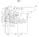
- FIG. 1 is a cross-sectional view illustrating a media deposit apparatus according to an embodiment of the present invention.
- FIG. 2 is a cross-sectional view for describing a circulation direction of paths used in the media deposit apparatus of FIG. 1 .
- FIG. 3 is a perspective view illustrating components of the media deposit apparatus of FIG. 1 .
- FIGS. 4A , 4 B, 4 C, 4 D, 4 E, and 4 F are cross-sectional views for describing paths of transferring media in the media deposit apparatus of FIG. 1 .
- FIG. 5 is a flowchart illustrating a method of controlling the media deposit apparatus of FIG. 1 according to an embodiment of the present invention.
- the media deposit apparatus is only an example of an automatic teller machine (ATM) and may also be applicable to other types of ATMs such as a media depositing/withdrawing apparatus, and the like.
- ATM automatic teller machine
- FIG. 1 is a cross-sectional view illustrating a media deposit apparatus 100 according to an embodiment of the present invention
- FIG. 2 is a cross-sectional view for describing a circulation direction of paths used in the media deposit apparatus 100 of FIG. 1 .
- the media deposit apparatus 100 includes a housing 110 that forms an external shape and internally includes various types of parts.
- a media deposit portion 111 is provided in one side of the housing 110 so that a customer may deposit media such as cash, checks, and the like.
- the housing 110 includes a plurality of belts and a plurality of rollers to form a plurality of paths for transferring the deposited media.
- the plurality of paths may include a deposit circulation path DCP, a temporary circulation path TCP, and a media transfer path MTP.
- the deposit circulation path DCP may connect the media deposit portion 111 and a rejection portion, for example, a rejection box RJ (hereinafter, rejection portion RJ) for rejecting abnormal media among the deposited media.
- the temporary circulation path TCP may connect a temporary stack portion, for example, an escrow box ES (hereinafter, temporary stack portion ES), for temporarily storing normal media among the deposited media.
- the media transfer path MTP may connect the temporary circulation path TCP and a media storage portion, for example, a cassette box CA (hereinafter, a media storage portion CA) for receiving the temporarily stored media.
- the media deposit apparatus 100 may further include a specific transfer path STP that may connect the temporary circulation path TCP and a retraction portion, for example, a retraction box RT (hereinafter, retraction portion RT) for retracting uncollected media, or a specific storage portion, for example, a forged note box FN (hereinafter, specific storage portion FN) for storing forged media.
- a specific transfer path STP that may connect the temporary circulation path TCP and a retraction portion, for example, a retraction box RT (hereinafter, retraction portion RT) for retracting uncollected media
- a specific storage portion for example, a forged note box FN (hereinafter, specific storage portion FN) for storing forged media.
- the media deposited in the media deposit portion 111 may pass through a deposit path 113 that is formed on an outlet side of the media deposit portion 111 .
- the deposited media is paper money for ease of description.
- a plurality of rollers (not shown) may be provided in the outlet side of the media deposit portion 111 to send the deposited media to the deposit path 113 .
- the deposit path 113 may include two belts (not shown) that are provided to face each other and rollers to drive the belts. Also, the deposit path 113 may include a single belt and a guide surface (not shown) to face the single belt.
- the media may be transferred to a media recognition portion 112 along the deposit path 113 .
- the media recognition portion 112 may include various types of sensors, an image scanner, a magnetic ink character recognition (MICR), and the like, to thereby determine whether the deposited media is normal or abnormal. Specifically, the media recognition portion 112 may determine the abnormal media such as double-sheet media, folded media, and the like. Also, the media recognition portion 112 may determine whether the deposited media is forged.
- the deposit circulation path DCP may be provided on an outlet side of the media recognition portion 112 and the rejection portion RJ may be mounted on one side of the deposit circulation path DCP.
- the rejection portion RJ may be mounted on one side of the deposit circulation path DCP.
- a deposit transfer portion 120 to form the deposit circulation path DCP may include a first belt 121 that provides a tightening force to the media and circulates into a predetermined direction, and a plurality of first rollers 122 that supports and drives the first belt 121 .
- a first auxiliary belt 123 and a plurality of rollers (not shown) to drive the first auxiliary belt 123 may be provided on one side of the first belt 121 .
- the media may move between the first belt 121 and the first auxiliary belt 123 by the tightening force formed therebetween. In this instance, it is possible to transfer the media through the tightening force, formed between the first belt 121 and the guide surface, by including the guide surface instead of the first auxiliary belt 123 .
- a plurality of idlers (not shown) may be mounted on the guide surface to support the first belt 121 .
- the media determined as normal media at the media recognition portion 112 may not pass through the rejection portion RJ and instead may be transferred to the temporary stack portion ES.
- the temporary stack portion ES may be a type of box that functions to temporarily store normal media. The reason why the media is temporarily stored in the temporary stack portion ES is to collect sheet-based media and process the collected media based on a stack unit and thereby to enhance a deposit processing efficiency. Since the temporary stack portion ES includes a drum (not shown) and a band (not shown), the temporary stack portion ES may wrap the media around the drum or the band and thereby temporarily store the media instead of piling up the media.
- the temporary circulation path TCP may be formed between the deposit circulation path DCP and the temporary stack portion ES in order to transfer the media to the temporary stack portion ES.
- a temporary transfer portion 130 to form the temporary circulation path TCP may include a plurality of second belts 131 and 132 that circulates into a predetermined direction, and a plurality of second rollers 133 and 134 that drives the plurality of second belts 131 and 132 .
- a singe belt for example, the second belt 131 among the plurality of second belts 131 and 132 may circulate in a partial contact state with the first belt 121 of the deposit circulation path DCP.
- the deposit circulation path DCP and the temporary circulation path TCP may partially share each other's path. The tightening force occurring in the shared path may make the media smoothly move.
- the media may be transferred to the media storage portion CA that is provided in a lower portion of the housing 110 .
- the media transfer path MTP may be formed between the temporary stack portion ES and the media storage portion CA in order to transfer the media to the media storage portion CA.
- a media transfer portion 140 to form the media transfer path MTP may include a third belt 141 that gives a tightening force to the media and circulates into a predetermined direction, and a plurality of third rollers 142 that drive the third belt 141 .
- the third belt 141 may be provided in a partial contact state with the second belt 131 .
- the specific transfer path STP may be formed to transfer, to the specific storage portion FN, forged media determined at the media recognition portion 112 .
- the specific transfer path STP may contact with the temporary circulation path TCP to thereby share a portion thereof, and may also be connected to the specific storage portion FN.
- a specific transfer portion 150 to form the specific transfer path STP may include a fourth belt 151 that gives a tightening force to the media and circulates into a predetermined direction, and a plurality of fourth rollers 152 that drive the fourth belt 151 .
- the fourth belt 151 may be provided in a partial contact state with the plurality of second belts 131 and 132 .
- the media temporarily stored in the temporary stack portion ES may be generally transferred from the temporary stack portion ES to the media storage portion CA.
- the customer may not take any action for the media stored in the temporary stack portion ES.
- the media stored in the temporary stack portion ES may not be provided to the customer.
- the retraction portion RT may be provided.
- the media may be retracted to the retraction portion RT.
- the specific transfer path STP may be provided between the temporary circulation path TCP and the retraction portion RT in order to transfer the uncollected media from the temporary stack portion ES to the retraction portion RT.
- the retraction portion RT and the specific storage portion FN may be integrally formed on the specific transfer path STP. Further detailed description related thereto will be made later.
- the media storage portion CA may include two portions.
- the media storage portion CA may include a first media storage portion CA 1 that is connected to the media transfer path MTP and a second media storage portion CA 2 that is provided on one side of the first media storage portion CA 1 .
- an additional transfer path ATP may be further provided to transfer the media to the second media storage portion CA 2 .
- the additional transfer path ATP may contact with the temporary circulation path TCP to thereby share a portion thereof and may also be connected to the second media storage portion CA 2 .
- An additional transfer portion 160 to form the additional transfer path ATP may include a fifth belt 161 that gives a tightening force to the media and circulates into a predetermined direction, and a plurality of fifth rollers 162 that drives the fifth belt 161 .
- the fifth belt 161 may be provided in a partial contact state with the second belt 131 .
- How many media storage portions are constructed is a matter of selection and thus it may be desirable to additionally provide a transfer path according to the added media storage portion.
- the temporary circulation path TCP may be provided in a single path, or may be provided in two paths.
- the temporary circulation path TCP may include a first temporary circulation that contacts with the deposit circulation path DCP and the specific transfer path STP, and a second temporary circulation path that contacts with the media transfer path MTP.
- the second belt 131 may contact with the first belt 121
- another second belt 132 may contact with the third belt 141
- the first temporary circulation path may include the second belt 131 that contacts with the first belt 121
- the second temporary circulation path may include the second belt 132 that contacts with the third belt 141 .
- the reason to construct the temporary circulation path TCP into two paths is to prevent overloads from occurring at a driving unit during driving all the paths.
- the first belt 121 of the deposit circulation path DCP, the fourth belt 151 of the specific transfer path STP, and the second belt 131 that simultaneously contacts with the deposit circulation path DCP and the specific transfer path STP may be circulated by a first driving unit 224 .
- the other second belt 132 of the temporary circulation path TCP, the third belt 131 of the media transfer path MTP, and the fifth belt 161 of the additional transfer path ATP may be circulated by a second driving unit 234 .
- auxiliary belt on one side of the second belts 131 and 132 of the temporary circulation path TCP, that is, on one side opposite to a side where the media transfer path MTP or the additional transfer path ATP is formed.
- An auxiliary belt may be provided even on one side of the fourth belt 151 forming the specific transfer path STP. Also, it is possible to extend the first auxiliary belt 123 , provided on one side of the first belt 121 forming the deposit circulation path DCP, so that the first auxiliary belt 123 may contact with the fourth belt 151 . Referring to FIG. 1 , the first auxiliary belt 123 contacts with the fourth belt 151 of the specific transfer path STP. As described above, it is possible to enhance the tightening force by installing the guide surface instead of the above auxiliary belts.
- the media may be misguided.
- normal media between the deposit circulation path DCP and the temporary circulation path TCP may not be transferred towards the temporary circulation path TCP but may be transferred to the rejection portion RJ.
- abnormal media may not be transferred to the rejection portion RJ but may be transferred to the temporary stack portion ES via the temporary circulation path TCP.
- an additional device may be required to determine or to guide a transfer direction of corresponding media at a point where a contacting portion of the paths DCP, TCP, MTP, STP, and ATP ends.
- a plurality of gates 181 , 182 , 183 , 184 , and 185 may be provided around the first through the fifth belts 121 , 131 , 141 , 151 , and 161 , respectively, in order to selectively connect or disconnect the paths DCP, TCP, MTP, STP, and ATP.
- the deposit transfer portion 120 may include a temporary stack gate 181 among the plurality of gates 181 , 182 , 183 , 184 , and 185 .
- the temporary stack gate 181 may be provided at a location where a contact portion between the first belt 121 of the deposit circulation path DCP and the second belts 131 and 132 of the temporary circulation path TCP ends, that is, at a location where the media gets away from the contact portion between the first belt 121 and the second belts 131 and 132 based on a transfer direction of the media, to thereby guide the media to the rejection portion RJ or to the temporary circulation path TCP.
- the temporary stack gate 181 may perform a pivot motion to contact with the first belt 121 or with the second belts 131 and 132 , and may determine the transfer direction of the media.
- a solenoid (not shown) or a stepping motor (not shown) may be connected to a pivot axis of the temporary stack gate 181 .
- the temporary stack gate 181 may be provided between the deposit circulation path DCP and the temporary circulation path TCP to selectively convert a path of the media to the temporary circulation path TCP. Specifically, the temporary stack gate 181 may selectively convert the path of the media between the deposit circulation path DCP and the temporary circulation path TCP.
- a media storage gate 182 may be provided between the temporary circulation path TCP and the media transfer path MTP.
- the media transfer portion 140 may further include the media storage portion 182 .
- the media storage gate 182 functions to transfer, to the first media storage portion CA 1 , media that passes through a contact portion between the temporary circulation path TCP and the media transfer path MTP, or may transfer, to the specific transfer path STP, media that is temporarily stored in the temporary stack portion ES.
- the shape of the media storage gate 182 may be similar to the shape of the temporary stack gate 181 .
- the media storage gate 182 may perform a pivot motion between the second belt 131 and the third belt 141 .
- the media storage gate 182 may be provided between the temporary circulation path TCP and the media transfer path MTP to selectively convert the path of the media to the media transfer path MTP.
- a specific storage gate 183 may be provided between the temporary circulation path TCP and the specific transfer path STP to selectively convert the path of the media.
- the specific transfer portion 150 may further include the specific storage gate 183 .
- the specific storage gate 183 functions to transfer, to the retraction portion RT or to the rejection portion RJ, the media that is transferred from the temporary stack portion ES along the temporary circulation path TCP.
- the shape of the specific storage gate 183 may be similar to the shape of the temporary stack gate 181 or the media storage gate 182 .
- the specific storage gate 183 may perform a pivot motion between the second belts 131 and 132 , and the fourth belt 151 .
- the specific storage gate 183 may be installed at a location where a contact portion between the second belts 131 and 132 , and the fourth belt 151 ends.
- a forged note retraction gate 184 may be provided on the deposit circulation path DCP that is adjacent to the specific transfer path STP.
- the deposit transfer portion 120 may include the forged note retraction gate 184 .
- the forged note retraction gate 184 functions to transfer, to the specific storage portion FN and to the specific transfer path STP, media that is determined as forged media at the media recognition portion 112 .
- the forged media that is determined at the media recognition portion 112 may need to be immediately transferred to the specific storage portion FN without passing through the rejection portion RJ or the temporary stack portion ES.
- the forged note retraction gate 184 may be provided between the deposit circulation path DCP and the specific transfer path STP. Through this, it is possible to prevent the forged media from being transferred to the rejection portion RJ or the temporary stack portion ES.
- the additional transfer portion 160 may further include an additional transfer gate 185 that is provided between the temporary circulation path TCP and the additional transfer path ATP.
- the additional transfer gate 185 may be provided at a location where a contact portion between the second belts 131 and 132 of the temporary circulation path TCP and the fifth belt 161 of the additional transfer path ATP ends, to thereby guide normal media, temporarily stored in the temporary stack portion ES to the second media storage portion CA 2 .
- the shape of the additional transfer gate 185 may be similar to the shape of the aforementioned gates 181 , 182 , 183 , and 184 .
- the additional transfer gate 185 may perform a pivot motion between the second belts 131 and 132 , and the fifth belt 161 .
- the specific storage portion FN may be further provided to retract the forged media.
- the forged media determined at the media recognition portion 112 may be immediately transferred to the specific storage portion FN via the media deposit portion 111 and the media recognition portion 112 without passing through the rejection portion RJ or the temporary stack portion ES. Specifically, it may be desirable to construct transfer paths so that normal media, or torn or folded abnormal media may be transferred to the rejection portion RJ or the temporary stack portion ES, whereas the elaborately forged media may be immediately transferred to the specific storage portion FN without passing through the rejection portion RJ or the temporary stack portion ES.
- an amount of forged media is less than an amount of normal media. Accordingly, when the specific storage portion FN is provided in the same size as the media storage portion CA or the retraction portion RT, it may increase the entire size of the media deposit apparatus 100 , which may result in restricting an installation space of the media deposit apparatus 100 .
- an auxiliary gate 186 may be provided at a location where the specific transfer path STP is connected to the retraction portion RT.
- the auxiliary gate 186 functions to transfer, to the retraction portion RT, uncollected normal media that is transferred along the specific transfer path STP, or functions to transfer the forged media to the specific storage portion FN.
- the shape of the auxiliary gate 186 is similar to the shape of the aforementioned gates 181 , 182 , 183 , 184 , and 185 .
- a media guide 187 may be provided in a portion where the second belts 131 and 132 of the temporary circulation path TCP are connected to the temporary stack portion ES.
- the media guide 187 functions to connect an upper portion of the second belts 131 and 132 , and the temporary stack portion ES, or to connect a lower portion of the second belts 131 and 132 , and the temporary stack portion ES.
- the temporary stack portion ES may receive or transfer the media via the single outlet. In this instance, it is possible to smoothly guide the media, transferred to and from the temporary stack portion, by providing the media guide 187 in a portion adjacent to the outlet.
- the media to be transferred to the temporary stack portion ES along the temporary circulation path TCP may progress towards the temporary stack portion ES along an upper portion of the second belts 131 and 132 .
- the media to be transferred from the temporary stack portion ES may progress towards the media transfer path MTP along the lower portion of the second belts 131 and 132 . Accordingly, there is a need to selectively connect the temporary stack portion ES and either the upper portion or the lower portion of the second belts 131 and 132 .
- the shape and the pivot motion of the media guide 187 may be the same as or similar to the aforementioned shape and the pivot motion of the gates 181 , 182 , 183 , 184 , 185 , and 186 .
- FIG. 3 is a perspective view illustrating components of the media deposit apparatus 100 of FIG. 1 .
- FIG. 2 illustrates frames that include belts and rollers to form the paths DCP, TCP, MTP, STP, and ATP.
- DCP deoxyribonucleic acid
- the first belt 121 and the first rollers 122 that form the deposit circulation path DCP may be mounted to a first frame 124 .
- the first frame 124 is formed of a plurality of plate members that are spaced apart from each other at predetermined intervals.
- the first belt 121 or the first rollers 122 may be provided between plate members that are positioned in an approximately intermediate portion.
- a first auxiliary frame 125 including the first auxiliary belt 123 may be provided on one side of the first frame 124 .
- the guide surface may be provided instead of mounting the first auxiliary belt 123 on the first auxiliary frame 125 .
- the first auxiliary frame 125 may also be formed of a plurality of plate members that are spaced apart from each other at predetermined intervals.
- the second belts 131 and 132 , and the second rollers 133 and 134 that form the temporary circulation path TCP may be mounted to second frames 137 and 138 , respectively.
- Second auxiliary frames 139 a and 139 b for the second auxiliary belts 135 and 136 may be provided above the second frames 137 and 138 , respectively.
- Each of the second frames 137 and 138 , and the second auxiliary frames 139 a and 139 b may be formed of a plurality of plate members that are spaced apart from each other at predetermined intervals.
- the third belt 141 and the third roller 142 that form the media transfer path MTP may be mounted to a third frame 144 .
- a third auxiliary frame 145 may be provided on one side of the third frame 144 to install the third auxiliary belt 143 .
- each of the third frame 144 and the third auxiliary frame 145 may be formed of a plurality of plate members that are spaced apart from each other at predetermined intervals. It may be desirable to provide the third belt 141 and the third auxiliary belt 143 between the plate members that are positioned in an approximately intermediate portion.
- a fourth frame 153 that forms the specific transfer path STP may be provided on a left side of the third frame 144 .
- a fifth frame 164 that forms the additional transfer path ATP may be provided on a right side of the third frame 144 .
- the fourth frame 153 may be formed of a plurality of plate members.
- the fourth belt 151 may be provided between plate members that are positioned in an approximately intermediate portion.
- the fifth frame 164 may be formed of a plurality of plate members that are spaced apart from each other at predetermined intervals. It may be desirable to provide the fifth belt 161 between plate members that are positioned in an approximately intermediate portion.
- a fifth auxiliary frame 165 may be provided to be adjacent to the fifth frame 164 .
- belts or auxiliary belts are provided in a single row in the approximately intermediate portion, but the present invention is not limited thereto.
- a single row of belt may be provided in the middle of each of frames.
- at least two rows of belts may be provided to be in parallel with the transfer direction of the media.
- the gates 181 , 182 , 183 , 184 , and 185 may perform the pivot motion in a partially overlapping state with the first through the fifth frames ( 124 , 137 , 138 , 144 , 153 , and 164 ). Specifically, since the ends of the gates 181 , 182 , 183 , 184 and 185 are received in gaps between the plate members of the first through the fifth frames ( 124 , 137 , 138 , 144 , 153 , and 164 ), and thereby are partially overlapped, it is possible to prevent the media from being transferred to a wrong path and to guarantee an accurate transfer of the media.
- FIGS. 1 through 3 an operation of the media deposit apparatus 100 will be described with reference to FIGS. 1 through 3 , and FIGS. 4A through 4F .
- FIG. 4A illustrates a path of transferring, to the rejection portion RJ, abnormal media determined at the media recognition portion 112 .
- the temporary stack gate 181 may need to contact with the second belts 131 and 132 and thereby prevent the media from progressing towards the temporary circulation path TCP.
- the temporary stack gate 181 may contact with the second belts 131 and 132 whereby a passage or a gap for progressing the media may be formed between the first belt 121 and the temporary stack gate 181 .
- the media may be transferred to the rejection portion RJ via the passage or the gap.
- FIG. 4B illustrates a path of transferring, to the temporary stack portion ES, normal media determined at the media recognition portion 112 .
- the temporary stack gate 181 may be separated from the second belts 131 and 132 to thereby contact with the first belt 121 . Through this, a passage or a gap may be formed between the temporary stack gate 181 and the second belts 131 and 132 . The media may be transferred to the temporary stack portion ES via the passage or the gap.
- FIG. 4C illustrates a path of transferring, to the first media storage portion CA 1 , normal media that is temporarily stored in the temporary stack portion ES.
- the media guide 187 may perform a pivot motion so that the stored media may be transferred along a lower portion of the second belts 131 and 132 .
- the media storage gate 182 may contact with the second belts 131 and 132 so that the media being transferred along the lower portion of the second belts 131 and 132 may pass through a contact portion between the second belts 131 and 132 , and the third belt 141 and then be transferred towards the media transfer path MTP.
- the media may need to initially pass through the contact portion between the second belts 131 and 132 , and the third belt 141 and then be transferred to the media transfer path MTP.
- the media storage gate 182 may contact with the second belts 131 and 132 whereby a predetermined interval of passage or gap may be formed between the third belt 141 and the media storage gate 182 .
- the media may be transferred to the first media storage portion CA 1 via the passage or the gap.
- FIG. 4D illustrates a path of transferring forged media determined at the media recognition portion 112 .
- the media may need to be immediately transferred to the specific transfer path STP and the specific storage portion FN without passing through the rejection portion RJ or the temporary stack portion ES.
- the forged media may pass through the specific transfer path STP and then be immediately stored in the specific storage portion FN.
- a path for retracting the forged media may be formed to be short.
- FIG. 4E illustrates a path for transferring uncollected media from the temporary stack portion ES to the retraction portion RT.
- the stored media may progress along the lower portion of the second belt 131 via the media guide 187 .
- the media storage gate 182 may contact with the third belt 141 to thereby transfer the media towards the specific transfer path STP.
- the specific storage gate 183 may contact with the second belts 131 and 132 .
- the media passing through the specific transfer path STP via the passage or the gap between the specific storage gate 183 and the fourth belt 151 may be transferred to the retraction portion RT via the auxiliary gate 186 .
- FIG. 4F illustrates a path of returning media that is temporarily stored in the temporary stack portion ES but of which depositing is cancelled.
- the media may need to be returned to the media deposit portion 111 .
- the media may be dispensed into a direction opposite to a direction that the media is transferred to the temporary stack portion ES and then be returned into the clockwise direction of the temporary circulation path TCP and be transferred to the media deposit portion 111 via the rejection portion RJ.
- FIG. 2 illustrates circulation directions of the paths DCP, TCP, MTP, STP, and ATP used in the media deposit apparatus 100 of FIG. 1 .
- the above paths DCP, TCP, MTP, STP, and ATP may circulate into the predetermined direction in the media deposit apparatus 100 according to an embodiment. While maintaining the circulation direction as is, media may be transferred to each corresponding storage portion.
- the media deposit apparatus 100 having the five paths DCP, TCP, MTP, STP, and ATP has been described above, but the present invention is not limited thereto. Specifically, a number of paths may increase or decrease depending on a number of media storage portions, the size of the media deposit apparatus 100 , and the like. Also, whether to install the rejection portion RJ or the media storage portion CA may be determined based on a location or a space where the media deposit apparatus 100 is installed.
- FIG. 5 is a flowchart illustrating a method of controlling the media deposit apparatus 100 according to an embodiment of the present invention.
- the method of controlling the media deposit apparatus 100 may include operation S 100 of depositing media, operation S 101 of driving paths DCP, TCP, MTP, STP, and ATP to transfer the deposited media, operation S 102 of determining whether the deposited media is abnormal or whether the deposited media is forged, operation S 107 of transferring the media to a rejection portion, for example, a rejection box RJ when the deposited media is determined as abnormal media, operation S 103 of transferring and temporarily storing the media in a temporary stack portion, for example, an escrow box ES when the deposited media is determined as normal or genuine media, operation S 105 of transferring the temporarily stored media to a media storage portion, for example, a cassette box CA to thereby perform depositing of the normal or genuine media, operation S 106 of transferring media to a retraction portion, for example, a retraction box RT when depositing of the media is cancelled, or when media returned to a media deposit portion 111 is uncollected, and operation S 109
- the forged media may be immediately transferred to the specific storage portion FN without passing through the temporary stack portion ES or the rejection portion RJ.
- a customer may deposit the media via the media deposit portion 111 .
- the paths DCP, TCP, MTP, STP, and ATP may be driven to transfer the deposited media.
- the paths may maintain their own predetermined circulation direction.
- the deposit circulation path DCP among the paths DCP, TCP, MTP, STP, and ATP may be driven.
- the media deposited via the media deposit portion 111 may be transferred in a sheet unit along the deposit circulation path DCP.
- a path of the media may be selectively converted to the temporary circulation path TCP using the temporary stack gate 181 that is provided between the deposit circulation path DCP and the temporary circulation path TCP.
- the media is determined as abnormal media such as torn media or folded media in operation S 102 , it is determined whether to convert a path of the abnormal media to the rejection portion RJ and the abnormal media is transferred to the rejection portion RJ depending on a determination result in operation S 107 .
- the abnormal media transferred to the rejection portion RJ may be returned to the customer in operation S 108 .
- the media that is determined as normal or genuine media in operation S 102 may be transferred to the temporary stack portion ES and be temporarily stored in the temporary stack portion ES in operation S 103 .
- the temporary stack portion ES may be driven together in contact with the deposit circulation path DCP.
- the temporary circulation path TCP may be provided between the deposit circulation path DCP and the temporary stack portion ES.
- the path of normal media or genuine media may be converted to the temporary stack portion ES.
- a path of forged media may not be converted to the temporary stack portion Es and may be immediately transferred to the specific storage portion FN.
- the uncollected media may be transferred to the retraction portion RT in operation S 106 or may be returned to the media deposit portion 111 .
- the above operation of determining whether to convert the path of the media to the media storage portion CA may further include converting, to the media deposit portion 111 , a path of normal media that circulates together with the temporary circulation path TCP, when depositing of the media stored in the temporary stack portion ES is cancelled.
- the forged media may be immediately transferred to the specific storage portion FN without passing through the rejection portion RJ or the temporary stack portion ES in operation S 109 . For this, it may be determined whether to convert, to the specific storage portion FN, the path of the media that circulates together with the temporary circulation path TCP.
- the paths DCP, TCP, MTP, STP, and ATP of media to be transferred to corresponding storage portions RJ, ES, CA, RT, and FN may be determined by a pivot motion of the gates 181 , 182 , 183 , 184 , 185 , and 186 .
- the above operation of determining whether to convert the path of the media to the specific storage portion FN may include converting, to the specific storage portion FN or the retraction portion RT, a path of normal media that circulates together with the temporary circulation path TCP, when the media stored in the temporary stack portion ES is uncollected.
- a method of controlling the gates 181 , 182 , 183 , 184 , 185 , and 186 to control a media transfer will be the same as the aforementioned method and thus further detailed descriptions related thereto will be omitted here.
- paths for transferring media may partially share the paths with each other and thus it is possible to simplify a media path structure.
- a path of media in a state where a plurality of paths maintains their own predetermined circulation direction, a path of media may be determined by a pivot motion of gates that are formed between the plurality of paths. Accordingly, it is possible to enhance a media transfer efficiency and to reduce an inconvenience of changing the circulation direction of the paths.
- a driving unit to drive a plurality of media paths is separated, it is possible to prevent overloads and to enhance a convenience of maintaining and repairing a media deposit apparatus.
Landscapes
- Physics & Mathematics (AREA)
- General Physics & Mathematics (AREA)
- Business, Economics & Management (AREA)
- Accounting & Taxation (AREA)
- Finance (AREA)
- Engineering & Computer Science (AREA)
- Mechanical Engineering (AREA)
- Separation, Sorting, Adjustment, Or Bending Of Sheets To Be Conveyed (AREA)
Abstract
Description
Claims (5)
Applications Claiming Priority (2)
| Application Number | Priority Date | Filing Date | Title |
|---|---|---|---|
| KR1020080017380A KR100973873B1 (en) | 2008-02-26 | 2008-02-26 | Media deposit device and control method |
| KR10-2008-0017380 | 2008-02-26 |
Publications (2)
| Publication Number | Publication Date |
|---|---|
| US20090216365A1 US20090216365A1 (en) | 2009-08-27 |
| US8181764B2 true US8181764B2 (en) | 2012-05-22 |
Family
ID=40999075
Family Applications (1)
| Application Number | Title | Priority Date | Filing Date |
|---|---|---|---|
| US12/392,801 Expired - Fee Related US8181764B2 (en) | 2008-02-26 | 2009-02-25 | Media deposit apparatus and method for controlling the same |
Country Status (2)
| Country | Link |
|---|---|
| US (1) | US8181764B2 (en) |
| KR (1) | KR100973873B1 (en) |
Cited By (2)
| Publication number | Priority date | Publication date | Assignee | Title |
|---|---|---|---|---|
| US20120280034A1 (en) * | 2009-12-31 | 2012-11-08 | Nautilus Hyosung Inc. | Automatic teller machine |
| US20120279982A1 (en) * | 2009-12-31 | 2012-11-08 | Nautilus Hyosung Inc. | Automatic financial automation equipment and control method thereof |
Families Citing this family (3)
| Publication number | Priority date | Publication date | Assignee | Title |
|---|---|---|---|---|
| KR101314451B1 (en) * | 2011-12-30 | 2013-10-07 | 노틸러스효성 주식회사 | Automatic teller machine |
| CN103159091B (en) * | 2013-04-03 | 2016-05-11 | 广州广电运通金融电子股份有限公司 | A kind of banknote deposting/drawing out device |
| JP2024120681A (en) * | 2023-02-24 | 2024-09-05 | 旭精工株式会社 | Banknote Processing Device |
Citations (2)
| Publication number | Priority date | Publication date | Assignee | Title |
|---|---|---|---|---|
| US4542287A (en) * | 1982-07-12 | 1985-09-17 | Tokyo Shibaura Denki Kabushiki Kaisha | Automatic bank note transaction apparatus |
| US4726474A (en) * | 1984-05-08 | 1988-02-23 | Laurel Bank Machines Co., Ltd. | Circulating-type bill depositing and disbursing machine |
Family Cites Families (4)
| Publication number | Priority date | Publication date | Assignee | Title |
|---|---|---|---|---|
| KR20060123826A (en) * | 2005-05-30 | 2006-12-05 | 노틸러스효성 주식회사 | Withdrawal device of automatic teller machine |
| KR20070051989A (en) * | 2005-11-16 | 2007-05-21 | 노틸러스효성 주식회사 | Financial automation equipment with multiple withdrawals |
| KR101419427B1 (en) * | 2008-01-31 | 2014-07-14 | 노틸러스효성 주식회사 | Media deposit apparatus |
| KR100968299B1 (en) * | 2008-01-31 | 2010-07-07 | 노틸러스효성 주식회사 | Media deposit device and control method |
-
2008
- 2008-02-26 KR KR1020080017380A patent/KR100973873B1/en not_active Expired - Fee Related
-
2009
- 2009-02-25 US US12/392,801 patent/US8181764B2/en not_active Expired - Fee Related
Patent Citations (2)
| Publication number | Priority date | Publication date | Assignee | Title |
|---|---|---|---|---|
| US4542287A (en) * | 1982-07-12 | 1985-09-17 | Tokyo Shibaura Denki Kabushiki Kaisha | Automatic bank note transaction apparatus |
| US4726474A (en) * | 1984-05-08 | 1988-02-23 | Laurel Bank Machines Co., Ltd. | Circulating-type bill depositing and disbursing machine |
Cited By (4)
| Publication number | Priority date | Publication date | Assignee | Title |
|---|---|---|---|---|
| US20120280034A1 (en) * | 2009-12-31 | 2012-11-08 | Nautilus Hyosung Inc. | Automatic teller machine |
| US20120279982A1 (en) * | 2009-12-31 | 2012-11-08 | Nautilus Hyosung Inc. | Automatic financial automation equipment and control method thereof |
| US8807423B2 (en) * | 2009-12-31 | 2014-08-19 | Nautilus Hyosung Inc. | Automatic teller machine |
| US8814041B2 (en) * | 2009-12-31 | 2014-08-26 | Nautilus Hyosung Inc. | Automatic financial automation equipment and control method thereof |
Also Published As
| Publication number | Publication date |
|---|---|
| KR20090092083A (en) | 2009-08-31 |
| US20090216365A1 (en) | 2009-08-27 |
| KR100973873B1 (en) | 2010-08-03 |
Similar Documents
| Publication | Publication Date | Title |
|---|---|---|
| US12230091B2 (en) | Bill processing device | |
| KR910008806B1 (en) | Transacting device | |
| KR101089657B1 (en) | Paper sheet handling device | |
| US20120285787A1 (en) | Bill depositing and dispensing device | |
| JP5091628B2 (en) | Paper sheet handling equipment | |
| US8181764B2 (en) | Media deposit apparatus and method for controlling the same | |
| EP3211609B1 (en) | Multi-banknote cassette with movable stopper and banknote stacking method thereof | |
| US9087425B2 (en) | Circulation-type banknote/check deposit/withdrawal apparatus using lateral deposit/withdrawal scheme and method of handling banknotes and checks applied thereto | |
| KR20150063211A (en) | Medium processing apparatus | |
| KR100968299B1 (en) | Media deposit device and control method | |
| KR101965857B1 (en) | Media separating apparatus and financial device including the same | |
| KR100596310B1 (en) | Deposit and withdrawal device of recycling box from banknote | |
| US8496101B2 (en) | Medium recovery device for medium processing device | |
| KR20060112460A (en) | Withdrawal device of automatic teller machine | |
| KR101546334B1 (en) | Apparatus for transferring paper medium of Automatic Teller Machine | |
| KR200411493Y1 (en) | Withdrawal device of automatic teller machine | |
| RU2503064C2 (en) | Apparatus for depositing carriers and method of controlling said apparatus | |
| KR20100079812A (en) | Automatic teller machine and control method for the same | |
| KR100973872B1 (en) | Path change structure of media deposit device | |
| KR101099900B1 (en) | Withdrawal device of automatic teller machine | |
| JP2805699B2 (en) | Banknote deposit / withdrawal device | |
| KR20090084282A (en) | Media deposit device | |
| EP4239605B1 (en) | Sheet handling method and sheet handling apparatus | |
| KR20090084283A (en) | Media deposit device | |
| KR200389004Y1 (en) | Apparatus of drawing bills in a cash transaction machine |
Legal Events
| Date | Code | Title | Description |
|---|---|---|---|
| AS | Assignment |
Owner name: NAUTILUS HYOSUNG INC., KOREA, REPUBLIC OF Free format text: ASSIGNMENT OF ASSIGNORS INTEREST;ASSIGNORS:CHA, JIN HWAN;CHOI, YOUNG IL;LEE, DONG SIK;AND OTHERS;REEL/FRAME:022312/0918 Effective date: 20090224 |
|
| ZAAA | Notice of allowance and fees due |
Free format text: ORIGINAL CODE: NOA |
|
| ZAAB | Notice of allowance mailed |
Free format text: ORIGINAL CODE: MN/=. |
|
| STCF | Information on status: patent grant |
Free format text: PATENTED CASE |
|
| FEPP | Fee payment procedure |
Free format text: PAYOR NUMBER ASSIGNED (ORIGINAL EVENT CODE: ASPN); ENTITY STATUS OF PATENT OWNER: LARGE ENTITY |
|
| FPAY | Fee payment |
Year of fee payment: 4 |
|
| MAFP | Maintenance fee payment |
Free format text: PAYMENT OF MAINTENANCE FEE, 8TH YEAR, LARGE ENTITY (ORIGINAL EVENT CODE: M1552); ENTITY STATUS OF PATENT OWNER: LARGE ENTITY Year of fee payment: 8 |
|
| FEPP | Fee payment procedure |
Free format text: MAINTENANCE FEE REMINDER MAILED (ORIGINAL EVENT CODE: REM.); ENTITY STATUS OF PATENT OWNER: LARGE ENTITY |
|
| LAPS | Lapse for failure to pay maintenance fees |
Free format text: PATENT EXPIRED FOR FAILURE TO PAY MAINTENANCE FEES (ORIGINAL EVENT CODE: EXP.); ENTITY STATUS OF PATENT OWNER: LARGE ENTITY |
|
| STCH | Information on status: patent discontinuation |
Free format text: PATENT EXPIRED DUE TO NONPAYMENT OF MAINTENANCE FEES UNDER 37 CFR 1.362 |
|
| FP | Lapsed due to failure to pay maintenance fee |
Effective date: 20240522 |