US816632A - Apparatus for display advertising. - Google Patents
Apparatus for display advertising. Download PDFInfo
- Publication number
- US816632A US816632A US18013003A US1903180130A US816632A US 816632 A US816632 A US 816632A US 18013003 A US18013003 A US 18013003A US 1903180130 A US1903180130 A US 1903180130A US 816632 A US816632 A US 816632A
- Authority
- US
- United States
- Prior art keywords
- panels
- display
- panel
- chains
- series
- Prior art date
- Legal status (The legal status is an assumption and is not a legal conclusion. Google has not performed a legal analysis and makes no representation as to the accuracy of the status listed.)
- Expired - Lifetime
Links
Images
Classifications
-
- G—PHYSICS
- G09—EDUCATION; CRYPTOGRAPHY; DISPLAY; ADVERTISING; SEALS
- G09F—DISPLAYING; ADVERTISING; SIGNS; LABELS OR NAME-PLATES; SEALS
- G09F11/00—Indicating arrangements for variable information in which the complete information is permanently attached to a movable support which brings it to the display position
- G09F11/12—Indicating arrangements for variable information in which the complete information is permanently attached to a movable support which brings it to the display position the display elements being carried by endless belts, chains, or the like
Definitions
- WITNESSES. I (2 0: $22 By Y m A TTORNE K No. 816,632. PATENTED APR. 3, 1906. E. 0. WILUOXa APPARATUS FOR DISPLAY ADVERTISING.
- My invention relates to an apparatus for display advertising and kindred uses and the invention consists in an apparatus adapted to be enlarged to any desired or practical dimensions, both in length and elevation and in the number of changes on the display-field, all substantially as shown and described, and particularly pointed out in the claims.
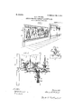
- Figure 1 is a perspective view of the apparatus as it is seen with a single advertisement covering its entire field and at rest for display purposes.
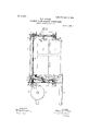
- Fig. 2 is an enlarged front view of a portion of two of the numerous panels seen in Fig. 1 and showing some of the operating mechanism connected therewith.
- Fig. 3 is a side sectional view on line 3 3, Fig. 2, of one set of panels.
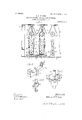
- Fig. 4 is a plan view corresponding to line 4 4, Fig. 2, and disclosing two complete sets of panel mechanisms and one partially complete.
- Fig. 5 is a perspective view of one of the several carrying-bars or bolsters for the panels, and
- Fig. 6 is a perspective view of one of the roller-carrier links for said bars or bolsters.
- Fig. 7 is a perspective view of one of the front sprocketwheels for the endless chains operating the panels and showing means for alining the panels, as hereinafter fully described.
- Fig. 8 is a modification of the means for supporting the panels.
- the apparatus is designed more especially, though not necessarily, for
- frame A which may be built up out of wood or metal, or partly of both, and which should be of such strength and endurance as to withstand storms and not to show the effects of possible contraction and expansion with changing temperatures.
- Any framework or structural support which has these characteristics and otherwise serves the purpose of my invention may be used, and its length, depth, and height are dependent on the nature or extent of the display to be made thereon.
- the frame is inclosed to protect the operating mechanism from exposure to moisture.
- the operating mechanism is mounted in or upon this frame, so that the entire apparatus is selfcontained and can be moved from place to place, if desired.
- T 0 these ends also frame A may be of a knockdown character and taken down and erected at pleasure; but it is chiefly designed to be perma nent where erected.
- Fig. 1 the frame is shown as having a display surface or field comprising a large number of panels O, standing perpendicular or upright edge to edge and in the same plane, so as to form a perfectly even and practically unbroken surface throughout.
- the arrangement of the displaypanels upon their ends or upright is of the very essence of this invention and entirely new, as I believe, and original with me and is valu able on many accounts, and especially because it enables me to build a displaysurface of any length that the eye can compass at an observing distance-say forty, sixty, or even a hundred feet or more in length, if that be desirable. Then, again, the elevation of the surface or field may by this disposition of the panels be made as high as can be desired-say from five to ten feet and upward.
- the said floor may be of wood, sheet metal, or other suitable material and at such distance above ground or the bottom portion of the frame as the local conditions and the display to be made may suggest; but while I prefer a common floor for all the panels, I may provide a separate end support for each set or series of panels, and for that matter I may dispense entirely with a bottom support and suspend the panels from their upper ends, as in Fig. 8.
- This upright or endwise arrangement of the panels has the further material advantage of requiringonly a one end support instead of two.
- the depth of the main frame front to rear is measurably determined by the number of panels in any one set or series, and four are shown in this machine is one such link-carrier for each panel.
- Fig. 4 There may be one or more, and the length of the machine is dependent on the number of series or sets of panels used. Two such sets or series are shown complete in Fig. 4:, and the panels in each set are connected by endless chains D and D above and below, respec tively.
- the chains are of the sprocket type in this instance.
- Each panel is equipped with a carrying-bar or bolster B and B at the respective ends, and the bar B in this instance serves as a bolster to carry the weight of the panel.
- Said bars have ears I) at their sides and ends, through which the panels are fastened by bolts or the like.
- Said bars B and B have central vertical holes to rotatably engage over or upon spindles 5 on the sprocket-chains D and D.
- the carrier E which constitutes also a link in chain D, has a spindle 5, adapted to enter bar B, and there Said link has a single wheel or roller in this instance; but there might be any equivalent wheel or rolling mechanism or medium for sustaining the panels or the chains by which they are connected and conveyed, as obviously it would be easy to modify the arrangement shown and get practically the same effect in conveying the panels about their circuit with their weight resting upon said means. Practically the same arrangement is provided above for connection between chain D and the panels, except that the rollers are omitted.
- the carrier-bars B and B are shown as deepened at their middle so as to give sufficient depth of bearing on spindles or bolts 5 to balance the panels evenly at their ends, and there are also vertical substantially V- shaped ribs 6 on this enlarged portion which help to locate the panels centrally as they come into the field for display, as will be seen farther along.
- Each set of panels also has its own operating-shaft G, arranged vertically at the front of the machine and carrying sprocket-wheels G and G for the respective sprocket-chains D and D, above and below.
- the lower wheel G is provided at its top and the upper wheel G at its bottom with a fiat or straight alining face 7, having a central vertical notch 8 of V-shape adapted to receive the ⁇ l-shaped rib 6 on bar or bolster B and B, and the said parts are so constructed and arranged altogether that the face 7 and its notch 8 are timed exactly with the panels in that set, and all panels in all the sets are timed alike, thus always bringing rib 6 into notch 8 when the panels are in display position.
- alining faces 7 above and below at the right time and brought into accurate alinement with all the other panels of that display series across the then present field as in Fig. 1.
- Power is applied to the machine through drive-gear H and shaft L, carrying bevelgears 10, which mesh with gears 12 on shafts G.
- a pinion 14 on shaft L is engaged by gear H, and the said gear is of a mutilated pattern, having a smooth periphery except a segmental portion thereof, which has teeth h, and these teeth are numerous enough to retire the present panel and bring the next succeeding one up to showing position.
- the period of rest is governed by the time it requires wheel H to travel over its ungeared portion, and the speed of its travel is the determining factor as to the time each panel shall remain in the field.
- a blank portion 15 on pinion 14 bears upon the smooth periphery of wheel H and. keeps said pinion from rotation until it reaches teeth h, and this makes all the lines of panel-controlling mechanism practically rigid for the time being.
- the panels are all alike rotatable axially at each end, as already described, for reversal. If they were not reversed, only four instead of eight changes would be afforded.
- Reversal is effected by means of two arms or projections N for each set of panels. These approximate a V shape in arrangement, into which the panels are carried, as seen in Fig. 4.
- the said panels travel forward into or within these arms edge forward relatively as they come from display and are reversed as the chains pass around their sprockets by throwing the opposite edge of the panel to the front.
- the edge 16 was ahead in the direction of travel from display, but in the change of direction back the edge 17 is thrown to the front instead and brings the opposite sides of the panel to view on the field.
- Such reversal proceeds in like manner and at the same time throughout the system and brings first one edge to the front and then the other, and so on continually.
- Power is communicated to gear H by gear K on the same shaft, as shown here. Any other means for applying power to said shaft may be used.
- Guide-rollers O on the insides of the several sets of panels serve to keep the blades in their place and facilitate their travel without rotation on their pivots.
- Fig. 8 I show a modification of the ITO means for carrying the panels, in which they are suspended from a track or rail R above, and the carrier-link of chain D is modified to adapt it to this use.
- the carrying-roller being above, no bottom roller need be used, and in a sense this is a mere reversal of the carrying mechanism shown in Figs. 2 and 6.
- a panel in the sense in which the word is used herein is a flat-sided member or part of any suitable width, length, and thickness and which may be a plain wooden board or a sheet of metal or a special construction of any suitable kind, and alternation designations would be blades, vanes, plates, and the like.
- each-transverse set of vanes "s independent of all the others, except as all are driven from the same shaft, and each set contributes one panel to the series or row of panels on the exhibition-line, as seen in Fig. 1 and at the front in Fig. 4.
- l/Vhat I claim is 1.
- a series of endless conveyers parallel with each other a series of panels pivotally connected with each of said conveyers, means to reverse said panels on their pivots, and means adapted to lock each panel against rotation on its pivots at a predetermined point in its travel.
- a display-machine for advertising and the like comprising parallel sets of endless conveyers and a series of perpendicularlydisposed panels pivotally mounted on each set of conveyers, supplementary traveling supports to sustain the weights of each panel, and means adapted to lock each panel against rotation on its pivot at a predetermined point in its travel.
- a machine as described comprising a series of upright panels and endless connections flexibly uniting said panels, a floor supporting said panels and wheels around which said endless connections travel and ro tatable parts between said connections adapted to keep the panels in right traveling relations, substantially as described.
- a series of panels set endwise and endless chains in which the said panels are rotatably pivoted at each end, rollers on said chains adapted to support the weight of each panel in its travel, a support over which said rollers are adapted to ride, and a locking device adapted to rigidly hold each panel against pivotal rotation at a predetermined point in its travel.
- a series of panels and supports for the panels having holes centrally disposed, endless chains for conveying said panels, spindles on said chains loosely engaged in said holes and rollers on said spindles to carry the panels, a support for said rollers, a set of sprocketwheels for said chains, and a member on one of said sets of wheels adapted to lock each panel against rotation on its respective spindles when opposite thereto.
Landscapes
- Physics & Mathematics (AREA)
- General Physics & Mathematics (AREA)
- Engineering & Computer Science (AREA)
- Theoretical Computer Science (AREA)
- Displays For Variable Information Using Movable Means (AREA)
Description
PATENTED APR. 3, 1906.
E. 0. WILGOX. APPARATUS FOR DISPLAY ADVERTISING.
APPLICATION FILED NOV. 6 1903.
3 SHEETS-SHEET 1.
fiYYE/YTUR El /f f /fUF E. 0. WILGOX. APPARATUS FOR DISPLAY ADVERTISING.
APPLICATION IILBD NOV. 6- 1903.
.PATENTED APR. 3, 1906.
3 SHEETS-SHEET 2.
WITNESSES. I (2 0: $22 By Y m A TTORNE K No. 816,632. PATENTED APR. 3, 1906. E. 0. WILUOXa APPARATUS FOR DISPLAY ADVERTISING.
APPLIGATION FILED NOV. 6 1903.
' 3 SHEETS-SHEET 3.
A TIL IT. I JHVENTUR @hee Q. 6b. 491/4 ELMORE O. I/VILOOX, OF CLEVELAND, OHIO.
APPARATUS FOR DISPLAY ADVERTISING.
Specification of Letters Patent.
Patented April 3, 1906.
lrmlioation filed November 6. 1903. Serial No. 180,130.
To all whom it may concern:
Be it known that I, ELMORE O. VVILoox, a citizen of the United States, residing at Cleveland, in the county of Cuyahoga and State of Ohio, have invented certain new and useful Improvements in Apparatus for Display Advertising; and I do declare that the following is a full, clear, and exact description of the invention, which will enable others skilled in the art to which it appertains to make and use the same.
My invention relates to an apparatus for display advertising and kindred uses and the invention consists in an apparatus adapted to be enlarged to any desired or practical dimensions, both in length and elevation and in the number of changes on the display-field, all substantially as shown and described, and particularly pointed out in the claims.
In the accompanying drawings, Figure 1 is a perspective view of the apparatus as it is seen with a single advertisement covering its entire field and at rest for display purposes. Fig. 2 is an enlarged front view of a portion of two of the numerous panels seen in Fig. 1 and showing some of the operating mechanism connected therewith. Fig. 3 is a side sectional view on line 3 3, Fig. 2, of one set of panels. Fig. 4 is a plan view corresponding to line 4 4, Fig. 2, and disclosing two complete sets of panel mechanisms and one partially complete. Fig. 5 is a perspective view of one of the several carrying-bars or bolsters for the panels, and Fig. 6 is a perspective view of one of the roller-carrier links for said bars or bolsters. Fig. 7 is a perspective view of one of the front sprocketwheels for the endless chains operating the panels and showing means for alining the panels, as hereinafter fully described. Fig. 8 is a modification of the means for supporting the panels.
As thus shown the apparatus is designed more especially, though not necessarily, for
out-of-door advertising-work in which life size and even exaggerated sizes may be shown, according to the elevation of the displaysurface. To these ends I construct the machine with a suitable frame A, which may be built up out of wood or metal, or partly of both, and which should be of such strength and endurance as to withstand storms and not to show the effects of possible contraction and expansion with changing temperatures. Any framework or structural support which has these characteristics and otherwise serves the purpose of my invention may be used, and its length, depth, and height are dependent on the nature or extent of the display to be made thereon. For outdoor uses especially the frame is inclosed to protect the operating mechanism from exposure to moisture. The operating mechanism is mounted in or upon this frame, so that the entire apparatus is selfcontained and can be moved from place to place, if desired. T 0 these ends also frame A may be of a knockdown character and taken down and erected at pleasure; but it is chiefly designed to be perma nent where erected.
In Fig. 1 the frame is shown as having a display surface or field comprising a large number of panels O, standing perpendicular or upright edge to edge and in the same plane, so as to form a perfectly even and practically unbroken surface throughout.
The arrangement of the displaypanels upon their ends or upright is of the very essence of this invention and entirely new, as I believe, and original with me and is valu able on many accounts, and especially because it enables me to build a displaysurface of any length that the eye can compass at an observing distance-say forty, sixty, or even a hundred feet or more in length, if that be desirable. Then, again, the elevation of the surface or field may by this disposition of the panels be made as high as can be desired-say from five to ten feet and upward.
Now in further carrying out this invention practically I have preferably provided for supporting all said panels in like manner upon a fioor 2 common to all the panels. The said floor may be of wood, sheet metal, or other suitable material and at such distance above ground or the bottom portion of the frame as the local conditions and the display to be made may suggest; but while I prefer a common floor for all the panels, I may provide a separate end support for each set or series of panels, and for that matter I may dispense entirely with a bottom support and suspend the panels from their upper ends, as in Fig. 8. This upright or endwise arrangement of the panels has the further material advantage of requiringonly a one end support instead of two. The depth of the main frame front to rear is measurably determined by the number of panels in any one set or series, and four are shown in this machine is one such link-carrier for each panel.
There may be one or more, and the length of the machine is dependent on the number of series or sets of panels used. Two such sets or series are shown complete in Fig. 4:, and the panels in each set are connected by endless chains D and D above and below, respec tively. The chains are of the sprocket type in this instance. Each panel is equipped with a carrying-bar or bolster B and B at the respective ends, and the bar B in this instance serves as a bolster to carry the weight of the panel. Said bars have ears I) at their sides and ends, through which the panels are fastened by bolts or the like. Said bars B and B have central vertical holes to rotatably engage over or upon spindles 5 on the sprocket-chains D and D. Thus, as clearly seen in Fig. 6, the carrier E, which constitutes also a link in chain D, has a spindle 5, adapted to enter bar B, and there Said link has a single wheel or roller in this instance; but there might be any equivalent wheel or rolling mechanism or medium for sustaining the panels or the chains by which they are connected and conveyed, as obviously it would be easy to modify the arrangement shown and get practically the same effect in conveying the panels about their circuit with their weight resting upon said means. Practically the same arrangement is provided above for connection between chain D and the panels, except that the rollers are omitted.
The carrier-bars B and B are shown as deepened at their middle so as to give sufficient depth of bearing on spindles or bolts 5 to balance the panels evenly at their ends, and there are also vertical substantially V- shaped ribs 6 on this enlarged portion which help to locate the panels centrally as they come into the field for display, as will be seen farther along. Each set of panels also has its own operating-shaft G, arranged vertically at the front of the machine and carrying sprocket-wheels G and G for the respective sprocket-chains D and D, above and below. The lower wheel G is provided at its top and the upper wheel G at its bottom with a fiat or straight alining face 7, having a central vertical notch 8 of V-shape adapted to receive the \l-shaped rib 6 on bar or bolster B and B, and the said parts are so constructed and arranged altogether that the face 7 and its notch 8 are timed exactly with the panels in that set, and all panels in all the sets are timed alike, thus always bringing rib 6 into notch 8 when the panels are in display position. Thus it occurs also as each panel comes to the front for rest and display that it is met by the alining faces 7 above and below at the right time and brought into accurate alinement with all the other panels of that display series across the then present field, as in Fig. 1. Practically this field is as if it were i siaes a continuous and undivided surface, since all the panels come close together edge to edge. A totally different display may be made on the opposite sides of the same panels, and so on through the entire machine, so that with four panels in a set at least eight different displays or complete pictures can be successively produced. These may be consecutive in their order or wholly independent of each other in kind and character, and the detention at each pause may be for a greater or less time, as may be deemed best, the length of time being controlled by the speed of the machine in this instance.
, Power is applied to the machine through drive-gear H and shaft L, carrying bevelgears 10, which mesh with gears 12 on shafts G. A pinion 14 on shaft L is engaged by gear H, and the said gear is of a mutilated pattern, having a smooth periphery except a segmental portion thereof, which has teeth h, and these teeth are numerous enough to retire the present panel and bring the next succeeding one up to showing position.
The period of rest is governed by the time it requires wheel H to travel over its ungeared portion, and the speed of its travel is the determining factor as to the time each panel shall remain in the field. A blank portion 15 on pinion 14 bears upon the smooth periphery of wheel H and. keeps said pinion from rotation until it reaches teeth h, and this makes all the lines of panel-controlling mechanism practically rigid for the time being.
The panels are all alike rotatable axially at each end, as already described, for reversal. If they were not reversed, only four instead of eight changes would be afforded. Reversal is effected by means of two arms or projections N for each set of panels. These approximate a V shape in arrangement, into which the panels are carried, as seen in Fig. 4. The said panels travel forward into or within these arms edge forward relatively as they come from display and are reversed as the chains pass around their sprockets by throwing the opposite edge of the panel to the front. Thus the edge 16 was ahead in the direction of travel from display, but in the change of direction back the edge 17 is thrown to the front instead and brings the opposite sides of the panel to view on the field. Such reversal proceeds in like manner and at the same time throughout the system and brings first one edge to the front and then the other, and so on continually.
Power is communicated to gear H by gear K on the same shaft, as shown here. Any other means for applying power to said shaft may be used.
Guide-rollers O on the insides of the several sets of panels serve to keep the blades in their place and facilitate their travel without rotation on their pivots.
In Fig. 8 I show a modification of the ITO means for carrying the panels, in which they are suspended from a track or rail R above, and the carrier-link of chain D is modified to adapt it to this use. The carrying-roller being above, no bottom roller need be used, and in a sense this is a mere reversal of the carrying mechanism shown in Figs. 2 and 6.
A panel in the sense in which the word is used herein is a flat-sided member or part of any suitable width, length, and thickness and which may be a plain wooden board or a sheet of metal or a special construction of any suitable kind, and alternation designations would be blades, vanes, plates, and the like.
Practically each-transverse set of vanes "s independent of all the others, except as all are driven from the same shaft, and each set contributes one panel to the series or row of panels on the exhibition-line, as seen in Fig. 1 and at the front in Fig. 4.
l/Vhat I claim is 1. In a machine for display advertising and the like, a series of endless conveyers parallel with each other, a series of panels pivotally connected with each of said conveyers, means to reverse said panels on their pivots, and means adapted to lock each panel against rotation on its pivots at a predetermined point in its travel.
2. A display-machine for advertising and the like, comprising parallel sets of endless conveyers and a series of perpendicularlydisposed panels pivotally mounted on each set of conveyers, supplementary traveling supports to sustain the weights of each panel, and means adapted to lock each panel against rotation on its pivot at a predetermined point in its travel.
3. A machine as described comprising a series of upright panels and endless connections flexibly uniting said panels, a floor supporting said panels and wheels around which said endless connections travel and ro tatable parts between said connections adapted to keep the panels in right traveling relations, substantially as described.
4. A series of panels set endwise and endless chains in which the said panels are rotatably pivoted at each end, rollers on said chains adapted to support the weight of each panel in its travel, a support over which said rollers are adapted to ride, and a locking device adapted to rigidly hold each panel against pivotal rotation at a predetermined point in its travel.
5. In a machine for display advertising, a series of panels and supports for the panels having holes centrally disposed, endless chains for conveying said panels, spindles on said chains loosely engaged in said holes and rollers on said spindles to carry the panels, a support for said rollers, a set of sprocketwheels for said chains, and a member on one of said sets of wheels adapted to lock each panel against rotation on its respective spindles when opposite thereto.
6. The combination of the main frame, a plurality of sets of perpendicularly-disposed rotatable panels arranged side by side transversely of said frame, endless chains pivotally uniting the upper and lower ends of each set of panels, a floor and rollers to sustain the weight 01 each individual panel thereon, means connected with each set of panels to aline corresponding panels in the several sets at the front of the machine and thus produce a complete exhibiting-surface, and means to hold each panel against rotation on its pivot during part of its travel.
7. In a display advertising-machine, a series of display-panels, cross-bars supporting the lower ends of said panels, and a spindle and roller member for each cross-bar, in conbination with endless flexible connections engaging said spindle and roller member, and a rotating support for said connections having an interlocking member adapted to engage and hold each cross-bar against rotation on its spindle.
8. In a display advertising-machine, a series of display-panels and rigid pieces across the ends of said panels top and bottom, chains connecting said pieces having pivot connections centrally with said pieces,wheels carrying said chains, and interlocking members on said wheels and rigid pieces respectively constructed to aline said panels at the front of the machine, substantially as described.
' In testimony whereof I sign this specification in the presence of two Witnesses.
ELMORE O. I/VILOOX.
Witnesses:
H. T. FISHER, R. B. MosER
Priority Applications (1)
| Application Number | Priority Date | Filing Date | Title |
|---|---|---|---|
| US18013003A US816632A (en) | 1903-11-06 | 1903-11-06 | Apparatus for display advertising. |
Applications Claiming Priority (1)
| Application Number | Priority Date | Filing Date | Title |
|---|---|---|---|
| US18013003A US816632A (en) | 1903-11-06 | 1903-11-06 | Apparatus for display advertising. |
Publications (1)
| Publication Number | Publication Date |
|---|---|
| US816632A true US816632A (en) | 1906-04-03 |
Family
ID=2885114
Family Applications (1)
| Application Number | Title | Priority Date | Filing Date |
|---|---|---|---|
| US18013003A Expired - Lifetime US816632A (en) | 1903-11-06 | 1903-11-06 | Apparatus for display advertising. |
Country Status (1)
| Country | Link |
|---|---|
| US (1) | US816632A (en) |
Cited By (1)
| Publication number | Priority date | Publication date | Assignee | Title |
|---|---|---|---|---|
| US2546236A (en) * | 1948-09-20 | 1951-03-27 | John L Pflueger | Advertising apparatus |
-
1903
- 1903-11-06 US US18013003A patent/US816632A/en not_active Expired - Lifetime
Cited By (1)
| Publication number | Priority date | Publication date | Assignee | Title |
|---|---|---|---|---|
| US2546236A (en) * | 1948-09-20 | 1951-03-27 | John L Pflueger | Advertising apparatus |
Similar Documents
| Publication | Publication Date | Title |
|---|---|---|
| US2525555A (en) | Sectional support for portable conveyers | |
| US816632A (en) | Apparatus for display advertising. | |
| US651236A (en) | Elevator. | |
| US931570A (en) | Elevator. | |
| US1044547A (en) | Carrier or conveyer. | |
| US523674A (en) | Conveyer | |
| US722689A (en) | Sheet-glass carrier for leers. | |
| US1226730A (en) | Belt conveyer. | |
| US692604A (en) | Moving model for advertising purposes. | |
| US662709A (en) | Conveyer. | |
| US1240172A (en) | Elevator. | |
| US2917171A (en) | Sizing machine | |
| US1153416A (en) | Current-motor. | |
| US629704A (en) | Traveling shelving. | |
| US278050A (en) | ruddell | |
| US472467A (en) | Running-water motor | |
| US1179490A (en) | Exhibiting or displaying machine. | |
| US1006455A (en) | Combined conveyer and inspection-table. | |
| US1587713A (en) | Advertising display rack | |
| US1045221A (en) | Advertising device. | |
| US920538A (en) | Display apparatus. | |
| US793701A (en) | Multiple changeable sign. | |
| US3234674A (en) | Rotary advertising display | |
| US951599A (en) | Motion advertising device. | |
| US639655A (en) | Elevator and conveyer. |