US8152225B2 - Roof panel and cab with the same, and method of manufacturing cab - Google Patents

Roof panel and cab with the same, and method of manufacturing cab Download PDF

Info

Publication number
US8152225B2
US8152225B2 US12/526,293 US52629308A US8152225B2 US 8152225 B2 US8152225 B2 US 8152225B2 US 52629308 A US52629308 A US 52629308A US 8152225 B2 US8152225 B2 US 8152225B2
Authority
US
United States
Prior art keywords
cab
roof
roof panel
planar portion
bent portions
Prior art date
Legal status (The legal status is an assumption and is not a legal conclusion. Google has not performed a legal analysis and makes no representation as to the accuracy of the status listed.)
Active, expires
Application number
US12/526,293
Other versions
US20100320804A1 (en
Inventor
Takeshi Kamimae
Makoto Yomogita
Current Assignee (The listed assignees may be inaccurate. Google has not performed a legal analysis and makes no representation or warranty as to the accuracy of the list.)
Komatsu Ltd
Original Assignee
Komatsu Ltd
Priority date (The priority date is an assumption and is not a legal conclusion. Google has not performed a legal analysis and makes no representation as to the accuracy of the date listed.)
Filing date
Publication date
Application filed by Komatsu Ltd filed Critical Komatsu Ltd
Assigned to KOMATSU LTD. reassignment KOMATSU LTD. ASSIGNMENT OF ASSIGNORS INTEREST (SEE DOCUMENT FOR DETAILS). Assignors: KAMIMAE, TAKESHI
Assigned to KOMATSU LTD. reassignment KOMATSU LTD. ASSIGNMENT OF ASSIGNORS INTEREST (SEE DOCUMENT FOR DETAILS). Assignors: YOMOGITA, MAKOTO
Assigned to KOMATSU LTD. reassignment KOMATSU LTD. ASSIGNMENT OF ASSIGNORS INTEREST (SEE DOCUMENT FOR DETAILS). Assignors: KAMIMAE, TAKESHI
Publication of US20100320804A1 publication Critical patent/US20100320804A1/en
Application granted granted Critical
Publication of US8152225B2 publication Critical patent/US8152225B2/en
Active legal-status Critical Current
Adjusted expiration legal-status Critical

Links

Images

Classifications

    • BPERFORMING OPERATIONS; TRANSPORTING
    • B62LAND VEHICLES FOR TRAVELLING OTHERWISE THAN ON RAILS
    • B62DMOTOR VEHICLES; TRAILERS
    • B62D33/00Superstructures for load-carrying vehicles
    • B62D33/06Drivers' cabs
    • B62D33/0617Drivers' cabs for tractors or off-the-road vehicles
    • BPERFORMING OPERATIONS; TRANSPORTING
    • B23MACHINE TOOLS; METAL-WORKING NOT OTHERWISE PROVIDED FOR
    • B23KSOLDERING OR UNSOLDERING; WELDING; CLADDING OR PLATING BY SOLDERING OR WELDING; CUTTING BY APPLYING HEAT LOCALLY, e.g. FLAME CUTTING; WORKING BY LASER BEAM
    • B23K31/00Processes relevant to this subclass, specially adapted for particular articles or purposes, but not covered by only one of the preceding main groups
    • B23K31/02Processes relevant to this subclass, specially adapted for particular articles or purposes, but not covered by only one of the preceding main groups relating to soldering or welding
    • EFIXED CONSTRUCTIONS
    • E02HYDRAULIC ENGINEERING; FOUNDATIONS; SOIL SHIFTING
    • E02FDREDGING; SOIL-SHIFTING
    • E02F9/00Component parts of dredgers or soil-shifting machines, not restricted to one of the kinds covered by groups E02F3/00 - E02F7/00
    • E02F9/16Cabins, platforms, or the like, for drivers
    • E02F9/163Structures to protect drivers, e.g. cabins, doors for cabins; Falling object protection structure [FOPS]; Roll over protection structure [ROPS]
    • BPERFORMING OPERATIONS; TRANSPORTING
    • B23MACHINE TOOLS; METAL-WORKING NOT OTHERWISE PROVIDED FOR
    • B23KSOLDERING OR UNSOLDERING; WELDING; CLADDING OR PLATING BY SOLDERING OR WELDING; CUTTING BY APPLYING HEAT LOCALLY, e.g. FLAME CUTTING; WORKING BY LASER BEAM
    • B23K2101/00Articles made by soldering, welding or cutting
    • B23K2101/006Vehicles
    • YGENERAL TAGGING OF NEW TECHNOLOGICAL DEVELOPMENTS; GENERAL TAGGING OF CROSS-SECTIONAL TECHNOLOGIES SPANNING OVER SEVERAL SECTIONS OF THE IPC; TECHNICAL SUBJECTS COVERED BY FORMER USPC CROSS-REFERENCE ART COLLECTIONS [XRACs] AND DIGESTS
    • Y10TECHNICAL SUBJECTS COVERED BY FORMER USPC
    • Y10TTECHNICAL SUBJECTS COVERED BY FORMER US CLASSIFICATION
    • Y10T29/00Metal working
    • Y10T29/49Method of mechanical manufacture
    • Y10T29/49826Assembling or joining

Definitions

  • the present invention relates to a roof panel that composes a roof surface of work vehicles such as bulldozer, hydraulic excavator, wheel loader and dumper truck, and a cab including the roof panel and a method of manufacturing the cab.
  • Conventional work vehicles such as wheel loader, bulldozer and hydraulic excavator include a cab (operator compartment) as an operator's room that is composed of square steel pipes or deformed steel pipes, panels and the like that are coupled to each other.
  • Japanese Patent Laid-Open Publication No. 2002-249073 discloses a roof structure of a work vehicle cab that, in order to prevent that an outer roof composing a roof surface of a cab hangs down or is dented, includes a band plate of spring steel on an interior side of the outer roof.
  • the band plate of spring steel is arranged along the interior side surface of the outer roof that holds and supports the outer roof so that, after a roof panel made of resin is mounted on the cab, it is prevented that the roof panel is dented due to its self weight, external loads or the like. For this reason, it is necessary to add a support member on the cab compartment space side of the roof surface. As a result, the number of components is increased that compose the cab.
  • the roof panel is made of a steel plate
  • the roof panel may be distorted due to thermal contraction after a welding process in cab assembling procedure.
  • the roof surface may be dented.
  • a roof panel according to a first aspect of the present invention is a roof panel of a work vehicle cab.
  • the roof panel includes a planar portion and a plurality of bent portions.
  • the planar portion serves as the roof surface of the work vehicle cab.
  • the bent portions are formed on the outer periphery of the planar portion. The bent portions are bent at a predetermined angle(s) with respect to the planar portion toward an external side of the roof surface of the work vehicle cab.
  • the bent portions are formed on the outer periphery of the planar portion of the roof panel that composes a roof surface of a work vehicle cab, and are bent at a predetermined angle(s) with respect to the planar portion that serves as the roof surface.
  • the aforementioned bent portion refers to a portion that is formed on the periphery of the panel and is bent at a predetermined angle(s) (e.g., 2 to 8 degrees) externally of the roof surface.
  • a portion can be formed by a bender, a press or the like.
  • the aforementioned bent portions can be formed along edges of the roof panel that are opposed to each other.
  • the planar portion can have a generally quadrangular shape, and the aforementioned bent portions can be formed along the four edges of the planar portion.
  • the bent portions formed on the periphery of the roof panel can be held by clamps or the like to beam members for supporting the roof surface so that the roof surface of the cab bulges externally in welding. For this reason, even if a stress is generated in the planar portion by thermal contraction after welding and the like, it can prevent that the roof surface is dented.
  • the simply-configured roof panel can prevent that the roof surface is dented without constraint members that are required for the lower surface of a roof surface of the known roof panel to prevent that the roof surface is dented.
  • the bent portions extend along edges of the planar portion adjacent to each other.
  • the roof panel further includes a cut-out portion between the bent portions.
  • the bent portions are formed on the outer peripheral sides of the planar portion of the roof panel, and extend along adjacent edges of the planar portion that interpose a cut-out portion.
  • the bent portions extend along the edges of the planar portion adjacent to each other, it is possible to prevent that, if parts of the bent portions remain that will intersect each other, interference between the parts may cause deterioration of precise formation of the bent portions or deformation of the bent portions. For this reason, the bent portions can be precisely formed. As a result, the height of a bulge part of the planar portion can be precisely controlled in the assembling procedure of the cab. Therefore, it is possible to form a roof panel with a desired shape.
  • the bent portions are formed along edges of the planar portion that are opposed to each other.
  • bent portions are formed along edges of the planar portion that interpose the planar portion, and are opposed to each other.
  • the bent portions formed on sides of the planar portion can be held by clamps or the like to beam members of a cab so that the planar portion bulges upward of the roof surface. Therefore, in the case where the roof panel is mounted onto a roof part of a cab by welding, it is possible to prevent that the roof panel is dented by thermal contraction after welding and the like.
  • the planar portion in the roof panel according to the first or second aspect of the present invention, has a generally quadrangular shape, and the bent portions are formed along the four edges of the planar portion.
  • bent portions are formed along all the edges of the quadrangular planar portion that interpose the planar portion, and are opposed to each other.
  • two pairs of bent portions are formed on two pairs of sides of the planar portion opposed to each other, and can be held by clamps or the like so that the planar portion bulges upward of the roof surface. Therefore, in the case where the roof panel is mounted onto a roof part of a cab by welding, it is possible to prevent that the roof panel is dented by thermal contraction after welding and the like.
  • the planar portion has one of a generally quadrangular shape and a generally hexagonal shape.
  • a plate-shaped member with a generally quadrangular or hexagonal shape is used as a roof panel that composes a roof surface of a work vehicle cab.
  • bent portions are formed along edges of the quadrangular or hexagonal shape that are opposed to each other, for example, and can be tentatively held to beam members that support a roof surface so that the planar portion bulges upward in welding. Then, the roof panel is welded. As a result, it is possible to prevent that the planar portion is dented inward of a cab by thermal contraction after the welding and the like.
  • a work vehicle cab includes a roof surface formed by the roof panel according to the first or second aspect of the present invention, and a plurality of pillar members forming a framework portion of the cab.
  • a cab is provided in that the aforementioned roof panel is used as a roof surface.
  • the bent portions formed on the periphery of the roof panel can be held by clamps or the like to the beam members so that the roof surface of the cab bulges externally in welding. For this reason, even if a stress is generated in the planar portion by thermal contraction after welding, it can prevent that the roof surface is dented. As a result, it is possible to provide a simply-configured cab that can prevent that the roof surface is dented without constraint members that are required for the lower surface of a roof surface of the known roof panel to prevent that the roof surface is dented.
  • a work vehicle cab includes a roof surface formed by the roof panel according to the second aspect of the present invention, and a plurality of pillar members and a plurality of beam members forming a framework portion of the cab.
  • the pillar members are coupled at side surfaces thereof to the roof panel in contact with the cut-out portion of the roof panel.
  • pillar members that compose a framework portion of a cab are coupled at side surfaces of the pillar members to the roof panel in contact with the cut-out portion that is formed in the roof panel.
  • the pillar members are secured to a roof member and a floor member by welding, it is possible to weld the pillar members on the exterior side of a cab structure that is tentatively assembled. Therefore, it is possible to provide a cab that can be assembled with improved workability.
  • a method of manufacturing a work vehicle cab includes the following steps.
  • the outer peripheral parts of a plate-shaped member are bent to form a roof panel that includes a planar portion and bent portions.
  • the bent portions are bent at a predetermined angle(s) with respect to the planar portion.
  • the roof panel is placed on a roof part of the cab, and then the bent portions are held and tentatively secured on the roof part of the cab so that the planar portion bulges from the roof surface toward an external side of the work vehicle cab.
  • the roof panel is secured on the roof part of the cab by welding whereby forming the roof surface.
  • a cab is assembled in that the aforementioned roof panel is used as a roof surface.
  • bent portions are first formed in predetermined locations along certain edges of a planar portion of a plate-shaped member to form a roof panel (first step). Subsequently, the roof panel is placed on a roof part of a cab, and the bent portions are held on the cab side by clamps or the like (second step). In this step, since the bent portions are held on the cab side with being thrust, the planar portion budges upward. After that, the bent portions are partially or entirely secured to on the cab side by welding so that the planar portion serves as the roof surface (third step).
  • the bent portions may be firmly welded, after the bent portions are tentatively secured by tentative welding and the fasteners such as clamps are removed.
  • FIG. 1 is an external view showing a wheel loader, which includes a cab according to an embodiment of the present invention.
  • FIG. 2 is a perspective view showing the configuration of the cab, which is installed on the wheel loader shown in FIG. 1 .
  • FIG. 3 is an exploded view showing components that are included as a roof member that composes the cab shown in FIG. 2 .
  • FIG. 4 is a perspective view showing the roof member composed of the assembled components shown in FIG. 3 .
  • FIG. 5 is an exploded view showing components that are included as a floor member that composes the cab shown in FIG. 2 .
  • FIG. 6 is a perspective view showing the floor member composed of the assembled components shown in FIG. 5 .
  • FIG. 7 is an exploded perspective view showing that pillar members are laterally attached to the roof member shown in FIG. 4 and the floor member shown in FIG. 6 .
  • FIG. 8 is an exploded perspective view showing that the members that compose the cab shown in FIG. 2 are attached.
  • FIGS. 9( a ) through 9 ( c ) are a plan view, a front view and a side view, respectively, showing the configuration of a roof panel to be attached to a roof surface of the cab shown in FIG. 2 .
  • FIGS. 10 ( a ) and 10 ( b ) are a plan view and a side view, respectively, showing the roof panel, which is held in the roof surface of the cab shown in FIG. 2 .
  • FIGS. 11( a ) and 11 ( b ) are plan views showing manufacturing processes of the roof panel shown in FIG. 9( a ) or the like, while FIG. 11( c ) is a side view of the roof panel.
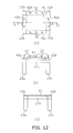
  • FIGS. 12 ( a ) through 12 ( c ) are a plan view, side views showing processes in that the roof panel formed in the processed shown in FIGS. 11( a ) through 11 ( c ) is secured on a roof part of the cab.
  • FIG. 13 is a flow chart showing the processes of manufacturing the cab shown in FIGS. 11( a ) through 12 ( c ).
  • FIG. 14 is an external view showing a bulldozer, which includes a cab according to another embodiment of the present invention.
  • FIGS. 15( a ) through 15 ( c ) are a plan view, a front view and a side view, respectively, showing the configuration of a roof panel to be attached to a roof surface of the cab shown in FIG. 14
  • FIG. 15( d ) is a side view of a modified roof panel.
  • FIGS. 16( a ) through 16 ( c ) are a plan view, a front view and a side view, respectively, showing the configuration of the roof panel that is attached to the roof surface of the cab shown in FIG. 14
  • FIG. 16( d ) is a side view of a modified roof panel.
  • FIGS. 17( a ) and 17 ( b ) are plan views showing manufacturing processes of the roof panel shown in FIG. 16( a ) or the like, while FIGS. 17( c ) and 17 ( d ) are side views of the roof panels.
  • FIGS. 18( a ) through 18 ( c ) are a plan view, side views showing processes in that the roof panel formed in the processed shown in FIGS. 17( a ) through 17 ( c ) is secured on a roof part of the cab.
  • FIGS. 19( a ) and 19 ( b ) are plan views showing manufacturing processes of a roof panel according to still another embodiment of the present invention, while FIG. 19( c ) is a side view of the roof panel.
  • FIGS. 20( a ) through 20 ( c ) are a plan view, side views showing processes in that the roof panel formed in the processed shown in FIGS. 19( a ) through 19 ( c ) is secured on a roof part of the cab.
  • a roof panel 21 a according to an embodiment of the present invention, a cab 20 that includes a roof surface including the roof panel 21 a , and a method of manufacturing the cab 20 .
  • the roof panel 21 a As shown in FIG. 1 , the roof panel 21 a according to this embodiment is applied to the cab 20 , which is installed on a wheel loader (work vehicle) 10 .
  • the wheel loader 10 includes a body 11 , a lift arm 12 , a bucket 13 , four tires 14 , and the cab 20 .
  • the lift arm 12 is mounted to a front part of the body.
  • the bucket 13 is mounted to the fore end of the lift arm 12 .
  • the tires 14 bear the body 11 , and revolve so that the body runs.
  • the cab 20 is mounted on an upper part of the body 11 .
  • the body 11 includes an engine compartment and actuator portions.
  • the engine compartment accommodates an engine (not shown).
  • the actuator portions actuate the lift arm 12 and the bucket 13 .
  • the lift arms 12 are arm members that lift the bucket 13 mounted to the fore end of the lift arms 52 , and are actuated by lift cylinders that are installed together.
  • the bucket 13 is mounted to the fore end of the arms 12 .
  • a bucket cylinder (not shown) is utilized for dumping and tilting of the bucket 53 .
  • the cab 20 forms an operator compartment assembled from a plurality of steel pipes and a plurality of steel plates.
  • the cab 20 is located in a part slightly frontward of the center of the body 11 .
  • the configuration and the assembling procedure of the cab 20 will be described bellow.
  • the cab 20 includes the roof member 21 , a floor member 22 , pillar members 23 , and a front cover member 24 .
  • the roof member 21 forms a top part of the cab 20 , i.e., the roof of the operator compartment. As shown in FIG. 3 , the roof member 21 includes a roof panel 21 a , the four beam members 21 b to 21 e , a reinforcing beam member 21 f , reinforcing members 31 , and joint members 32 .
  • the roof panel 21 a is a plate-shaped member with a generally square shape formed from a steel plate.
  • the four beam members 21 b to 21 e are secured along the four edges of the generally square shape.
  • the configuration of the roof panel 21 a 21 will be described in detail later.
  • the beam members 21 b to 21 e are a bar-shaped member formed from a steel pipe. As discussed above, the four beam members 21 b to 21 e are secured along the four edges of the generally square roof member (roof panel 21 a ) so that the beam members 21 b and 21 c extend along edges opposed to each other, and the beam members 21 d and 21 e extend along the other edges opposed to each other. All of the four beam members 21 b to 21 e have deformed sections.
  • the aforementioned roof panel 21 a engages with and secured onto recessed parts formed on the beam members 21 b to 21 e having the deformed sections with the beam members 21 b to 21 e being arranged to form a generally square shape. As shown in FIG.
  • joint space parts X are formed at the four corners of the square shape formed by the four beam members 21 b to 21 e (parts where the beam members 21 b to 21 e would intersect each other if have extended).
  • the joint space parts X have shapes corresponding to sectional shapes of the pillar members 23 .
  • the ends of each of the beam members 21 b to 21 e are shaped to engage with the sectional shape of each pillar member 23 to be attached to the joint space part X.
  • FIGS. 4 and 3 show the configuration of the roof panel 21 that is removed from the cab 20 , and the configuration of the roof panel 21 that is then exploded after the roof panel 21 is secured to the cab 20 as the roof surface.
  • FIGS. 4 and 3 do not show the assembling procedure of the cab 20 .
  • the reinforcing beam member 21 f is a bar-shaped member formed of a steel pipe with a generally rectangular shape in section. The ends of the reinforcing beam member 21 f are secured to substantially central parts of the beam members 21 d and 21 e . The thus-secured reinforcing beam member 21 f improves the rigidity of the roof member 21 .
  • the reinforcing members 31 are generally triangular plate-shaped members.
  • the reinforcing members 31 are arranged on the recessed parts of the deformed sections of the beam members 21 b to 21 e in intersection parts with the pillar members 23 . Since the reinforcing members 31 couple the beam members 21 b to 21 e and the pillar members 23 to each other, it is possible to improve the rigidity of the cab 20 . Also, since the reinforcing members 31 are arranged on the recessed parts of the deformed sections of the beam members 21 b to 21 e , it is possible to easily position the reinforcing members 31 .
  • the joint member 32 is formed by bending a plate member in its central part at a right angle.
  • the joint members 32 are arranged in the intersection parts of the beam members 21 b to 21 e , in other words, in the jointing space parts X. Specifically, as shown in FIG. 4 , the joint members 32 are secured onto the interior sides on ends of the steel pipes of the beam members 21 b to 21 e adjacent to each other to couple the adjacent beam members to each other.
  • the floor member 22 forms a bottom part of the cab 20 , i.e., the floor of the operator compartment.
  • the roof member 22 includes a floor plate 22 a , the four beam members 22 b to 22 e , a reinforcing beam member 22 f , and reinforcing members 33 and 34 .
  • the floor plate 22 a is a plate-shaped member with a generally home plate shape formed of a steel plate.
  • the four beam members 22 b to 22 e are arranged in a generally square shape, and are secured along edges of the plate.
  • the beam members 22 b to 22 e are a bar-shaped member formed from a steel pipe. As discussed above, the four beam members 22 b to 22 e are secured along the outer periphery of the generally square floor plate 22 a so that the beam members 22 b and 22 c extend along edges opposed to each other, and the beam members 22 d and 22 e extend along the other edges opposed to each other. Among the four beam members 22 b to 22 e , the beam members 22 b , 22 c and 22 e have deformed sections.
  • the aforementioned floor plate 22 a engages with and secured onto recessed parts that are formed on the beam members 22 b , 22 c and 22 e with the deformed sections with the beam members 22 b , 22 c and 22 e being arranged to form a generally square shape.
  • joint space parts X 2 are formed at the four corners of the square shape formed by the four beam members 22 b to 22 e (parts where the beam members 22 b to 22 e would intersect each other if have extended).
  • the joint space parts X 2 have shapes corresponding to sectional shapes of the pillar members 23 . In other words, the ends of each of the beam members 22 b to 22 e are shaped to fit in with the sectional shape of each pillar member 23 to be attached to the joint space part X 2 .
  • the reinforcing beam member 22 f is a bar-shaped member formed of a steel pipe with a generally rectangular shape in section. The ends of the reinforcing beam member 22 f are secured to substantially central parts of the beam members 22 b and 22 c . The thus-secured reinforcing beam member 22 f improves the rigidity of the floor member 22 .
  • the reinforcing members 33 are a generally triangular plate-shaped member similar to the reinforcing member 31 .
  • the reinforcing members 33 are arranged in intersection parts between the beam members 22 b to 22 e , and the pillar members 23 . Since the reinforcing members 33 couple the beam members 22 b to 22 e and the pillar members 23 to each other, it is possible to improve the rigidity of the cab 20 . Also, since the reinforcing members 33 are arranged on the recessed parts of the deformed sections of the beam members 22 b to 22 e , it is possible to easily position the reinforcing members 33 .
  • the reinforcing member 34 is arranged on the beam member 22 e arranged on the rear side.
  • the reinforcing member 34 is secured to the beam member 22 e , and the pillar members 23 c and 23 d that are arranged on the both ends of the beam member 22 e (see FIG. 7 ). Since the reinforcing member 34 couples the beam member 22 e and these pillar members 23 to each other, similar to the reinforcing member 33 , it is possible to improve the rigidity of the cab 20 . Also, similar to the aforementioned reinforcing members 33 , since the reinforcing member 34 is arranged on the recessed part of the deformed section of the beam member 22 b to 22 e , it is possible to easily position the reinforcing members 33 .
  • the pillar members 23 include the four pillar members 23 a to 23 d shown in FIG. 7 , and the two pillar members 23 e shown in FIG. 2 or the like.
  • the four pillar members 23 a to 23 d are laterally mounted into the joint space parts X formed at the four corners of the roof member 21 between the beam members 21 b to 21 e , and into the joint space parts X formed at the four corners of the floor member 22 between the beam members 22 b to 22 e .
  • Other two pillar members 23 e stand upright in the central parts of the side surfaces of the cab 20 .
  • the cab 20 is assembled by mounting the two pillar members 23 e , the front cover member 24 including a plurality of cover members, a side cover members 25 a and 25 b , and the rear cover member 25 c to the cab 20 .
  • the ends of the beam members 21 b to 21 e and the beam members 22 b to 22 e are shaped to fit in with the deformed sections X 1 of the pillar members 23 a to 23 d .
  • the pillar members 23 a to 23 d can be laterally mounted to the roof member 21 and the floor member 22 .
  • the pillar members 23 a to 23 d can be inserted into and fit in with the joint parts.
  • the pillar members 23 a to 23 d have deformed sections, recessed parts of the deformed sections can accommodate window glass, a door and the like to be mounted to the cab 20 .
  • the pillar members 23 a to 23 d are secured by welding in the assembling procedure discussed later.
  • the pillar members 23 a to 23 d can be welded from the exterior sides of the cab 20 .
  • the roof panel 21 a is formed of a metal plate-shaped component that includes a rectangular planar portion 41 and bent portions 42 a to 42 d .
  • the bent portions 42 a to 42 d extend along the four edges of the rectangular planar portion 41 .
  • the bent portions 42 a to 42 d are formed by bending constant width outer peripheral parts of a metal plate at a predetermined angle ⁇ toward one side.
  • the planar portion 41 extends along a horizontal axis HA.
  • the bent portions are bent at the angle ⁇ with respect to the horizontal axis HA.
  • the planar portion 41 is a flat surface portion that forms the roof surface of the cab 20 .
  • the bent portions 42 a to 42 d extend along the four edges of the rectangular planar portion 41 .
  • the planar portion 41 bulges externally of the roof surface.
  • the bent portions 42 a to 42 d are bent at the angle ⁇ with respect to the plane of the planar portion 41 , and extend along all the edges of the planar portion 41 opposed to each other.
  • the angle ⁇ is approximately 2 to 8 degrees.
  • the bent portions 42 a to 42 d are bent at the angle ⁇ by a bender or a press. That is, the bent portions 42 a to 42 d are formed to allow the planar portion 41 to bulge externally of the roof surface when the bent portions 42 a and 42 b formed along edges of the planar portion 41 opposed to each other are held by clamps 51 (see FIGS. 12( a ) and 12 ( b )) or the like.
  • cut-out portions 43 a to 43 d are formed between the bent portions 42 a to 42 d formed along all the edges of the planar portion 41 opposed to each other.
  • the cut-out portions 43 a to 43 d are formed by cutting out four corner parts of the rectangular roof panel 21 a .
  • the pillar members 23 a to 23 d are inserted into the cut-out portions 43 a to 43 d to form the cab 20 . Since the cut-out portions 43 a to 43 d are formed, it is possible to prevent that the bent portions 42 a to 42 d adjacent to each other intersect each other in the corner parts. Therefore, the bent portions 42 a to 42 d can be easily and precisely formed.
  • the cab 20 is manufactured as shown in a flowchart of FIG. 13 .
  • Step S 1 the bent portions 42 a to 42 d are formed in a plate-shaped member 21 a ′ shown in FIG. 11 ( a ) that has the cut-out portions 43 a to 43 d at the four corner parts so that the bent portions 42 a to 42 d extend along the four edges of the planar portion 41 as shown in FIGS. 11( b ) and 11 ( c ).
  • the bent portions 42 a to 42 d are bent externally of the roof surface, in other words, the bent portions 42 a to 42 d are bent toward a side to allow the planar portion 41 to bulge upward.
  • the angle of the bent portions 42 a to 42 d is approximately 2 to 8 degrees with respect to the plane of the planar portion 41 .
  • the angle of the bent portions 42 a to 42 d can be determined in consideration of the amount of thermal contraction after welding, and the degree of flatness of the roof surface after thermal contraction. For example, in the case where the bending angle of the bent portions 42 a to 42 d is 2 degrees with respect to the planar portion 41 , thermal contraction can make the roof surface of the cab 20 flat after welding.
  • Step S 2 (second step), the roof panel 21 a with the bent portions 42 a to 42 d shown in FIGS. 11( b ) and 11 ( c ) are placed on the roof part as the beam members 21 b to 21 e that serve as a top framework part of the cab 20 .
  • Step S 3 (second step), as shown in FIGS. 12( a ) and 12 ( b ), the bent portions 42 a to 42 d are held on the cab 20 side by the clamps 51 .
  • the aforementioned beam members 21 b to 21 e , and the aforementioned bent portions 42 a to 42 d are sandwiched and held by the clamps 51 . Since the bent portions 42 a to 42 d are thus held, as shown by arrows in FIG. 12( b ), tensile and compressive stresses are applied to the upper and lower surface sides of the planar portion 41 , respectively.
  • the roof panel 21 a will bulge externally of the roof surface.
  • each of the bent portions 42 a to 42 d is tentatively secured (retained) by arc-spot welding (tentative welding) at several points between a plurality of clamps 51 that hold each of the bent portions 42 a to 42 d with each of the bent portions 42 a to 42 d being held as shown in FIG. 12( b ).
  • Step S 5 since the roof panel 21 a is retained on the cab 20 side by tentative welding, all the clamps 51 are removed.
  • Step S 6 the entire periphery of the roof panel 21 a is held by tentative welding along the outer peripheral edges of the roof panel 21 a held on the cab 20 side by tentative welding so that the roof panel 21 a is fully secured on the roof part of the cab 20 (see FIG. 12( c )).
  • previously-welded parts apply a tensile stress to the roof panel 21 a toward the previously-welded parts.
  • the roof panel 21 a deforms so that the bulging part disappears that bulges externally of the roof surface.
  • the bending angle is previously determined so that, as shown in FIG. 12 , the shape of the upper surface of the roof panel 21 a becomes fully flat after deformation.
  • the several points of each of the bent portions 42 a to 42 d are held on the cab 20 side by the plurality of clamps 51 as shown in FIG. 12( a ) or the like.
  • the bent portions 42 a to 42 d are bent externally of the roof surface, when the bent portions 42 a to 42 d are held on the cab 20 side, the roof panel will bulge externally of the roof surface as shown in FIG. 12( b ).
  • the roof panel 21 a is then secured on the cab 20 side by welding. As a result, even if one surface of the planar portion 41 of the roof panel 21 a contracts due to the thermal contraction after welding and the like, it is possible to prevent that the roof surface is dented.
  • the simply-configured roof panel 21 a that includes the bent portions 42 a to 42 d along the outer periphery of the planar portion 41 can prevent that the roof surface of the cab 20 is dented or deformed without constraint members on the lower surface of a roof surface.
  • the roof panel 21 a is a member that composes the roof surface of the cab 20 installed on the wheel loader 10 shown in FIG. 1 .
  • the roof panel 21 a includes the planar portion 41 that serves as the roof surface of the cab 20 , and the bent portions 42 a to 42 d that are formed on the outer periphery of the planar portion 41 and are bent at a predetermined angle ⁇ with respect to the planar portion 41 .
  • the bent portions 42 a to 42 d serves as joint parts joined to the beam members 21 b to 21 e and the like, and as parts of the roof surface of the cab 20 .
  • the roof panel 21 a has the cut-out portions 43 a that are formed between the bent portions 42 a to 42 d formed along the edges of the planar portion 41 opposed to each other as shown in FIG. 11( b ).
  • the roof panel 21 a includes the bent portions 42 a and 42 b along edges of the planar portion 41 opposed each other, and the bent portions 42 c and 42 d along the other edges of the planar portion 41 opposed each other.
  • the roof panel 21 a includes the bent portions 42 a to 42 d along all the four edges of the rectangular planar portion 41 .
  • the roof panel 21 a is formed from a generally quadrangular panel as shown in FIGS. 9( a ) to 9 ( c ).
  • the planar portion 41 can easily bulge externally of the roof surface when the bent portions 42 a to 42 d are mounted on the roof part of the cab 20 .
  • the aforementioned roof panel 21 a serves as the roof surface as shown in FIG. 8 or the like.
  • the roof surface externally bulges before the welding and absorbs thermal contraction after the welding. Therefore, it is possible to provide the cab 20 that has an effect similar to the foregoing effect in that it is possible to prevent that the roof surface is dented or distorted after the welding.
  • the aforementioned roof panel 21 a serves as the roof surface as shown in FIG. 9( a ) or the like, and side surfaces of the pillar members 23 a to 23 d contact the roof panel 21 a in the cut-out portions 43 a to 43 d formed in the four corner parts of the roof panel 21 a.
  • the pillar members 23 a to 23 d can be laterally inserted and then welded from the exterior sides of the cab 20 . Therefore, the cab 20 can be assembled with improved workability.
  • Step S 1 the bent portions 42 a to 42 d are formed in predetermined locations in the plate-shaped member 21 a ′ (first step).
  • Step S 2 the roof panel 21 a is placed on the roof part, and then, in Step S 3 , the several points of each of the bent portions 42 a to 42 d are held on the cab 20 side by the clamps 51 (second step).
  • Step S 6 the roof panel 21 a is secured on the cab 20 side by welding (third step).
  • the roof panel 21 a is mounted on the roof part of the cab 20 in Step S 3 , the planar portion 41 can bulge externally of the roof surface. Therefore, after the welding in Step S 6 , it is possible to prevent that the roof surface is dented or distorted due to thermal contraction after the welding and the like.
  • a roof panel 71 a according to another embodiment of the present invention, a cab 120 that includes a roof surface including the roof panel 71 a , and a method of manufacturing the cab 120 .
  • the cab 120 is installed on a bulldozer 110 that includes a body 111 , lift arms 112 , a dozing blade 113 , and crawler belts 114 .
  • the roof panel 71 a with a generally hexagonal shape is used as a member that composes a roof surface of the cab 120 .
  • the generally hexagonal shape has a narrow edge of the roof panel 71 a on the vehicle front side in plan view.
  • the roof panel 71 a is formed of a metal plate-shaped component that includes a rectangular planar portion 91 and bent portions 92 a to 92 d .
  • the bent portions 92 b to 92 d extend along edges of the rectangular planar portion 91 except for a front edge of the rectangular planar portion 91 .
  • the bent portions 92 a to 92 d are formed by bending outer peripheral parts of a metal plate externally of the roof surface at a predetermined angle ⁇ with respect to the planar portion 41 .
  • an inclined portion 95 is bent downward along the front edge of the planar portion 91 at a predetermined angle ⁇ with respect to the planar portion 41 .
  • the planar portion 91 is a flat surface portion that forms the roof surface of the cab 120 .
  • the bent portions 92 b to 92 d extend along, except for the front edge, the other three edges of the rectangular planar portion 91 .
  • the planar portion 91 bulges externally of the roof surface.
  • the inclined portion 95 frontward protrudes along the shape of the roof surface of the cab 120 of the bulldozer 110 , and is bent downward at the angle ⁇ by a bender, a press or the like.
  • the angle ⁇ is determined within a range of 2 to 10 degrees according to the shape of the roof part to be mounted to the cab 120 .
  • the bent portions 92 a to 92 d are bent at the angle ⁇ with respect to the plane of the planar portion 91 .
  • the angle ⁇ is approximately 2 to 8 degrees.
  • the bent portions 92 a to 92 d are bent at the angle ⁇ by a bender or a press. That is, the bent portions 92 a to 92 d are formed to allow the planar portion 91 to bulge externally of the roof surface when the bent portions 92 a and 92 b formed along edges of the planar portion 91 opposed to each other are held by the clamps 51 (see FIGS. 18( a ) and 18 ( b )) or the like. Also, cut-out portions 94 a to 94 d are formed between the bent portions 92 b to 92 d formed along edges of the planar portion 91 opposed to each other.
  • the cut-out portions 94 a to 94 d are formed by cutting out four corner parts of the rectangular planar portion 91 of the roof panel 71 a .
  • the aforementioned pillar members 73 a to 73 d are laterally inserted into space parts of the cut-out portions 94 a to 94 d to form the cab 120 . Since the cut-out portions 94 a to 94 d are formed, it is possible to prevent that the bent portions 92 a to 92 d adjacent to each other intersect each other in the corner parts. Therefore, the bent portions 92 a to 92 d can be easily and precisely formed.
  • the cab 120 is manufactured as shown in a flowchart of FIG. 13 similar to the foregoing first embodiment.
  • Step S 1 the bent portions 92 b to 92 d , and the inclined portion 95 are formed in a plate-shaped member 71 a ′ shown in FIG. 17( a ) that has the cut-out portions 94 a to 94 d at the four corner parts of the planar portion 91 so that the bent portions 92 b to 92 d extend along, except for a front edge, the other three edges of the planar portion 91 as shown in FIGS. 17( b ) and 17 ( c ), and the inclined portion 95 extends along the front edge.
  • the inclined portion 95 protrudes frontward, and is bent downward.
  • the inclined angle of the inclined portion 95 is approximately about 2 to 10 degrees upward with respect to the plane of the planar portion 91 .
  • the inclined angle can be determined in consideration of the shape of the roof part of the cab 120 .
  • the angle of the bent portions 92 b to 92 d is approximately 2 to 8 degrees with respect to the plane of the planar portion 91 .
  • the angle of the bent portions 92 b to 92 can be determined in consideration of the amount of thermal contraction after welding, and the degree of flatness of the roof surface after thermal contraction. For example, in the case where the bending angle of the bent portions 92 a to 92 d is 2 degrees with respect to the planar portion 91 , thermal contraction can make the roof surface of the cab 120 flat after welding.
  • Step S 2 (second step), the roof panel 71 a with the inclined portion 95 and the bent portions 92 b to 92 d shown in FIGS. 17( b ) and 17 ( c ) are placed on the roof part of the cab 120 as shown in FIG. 18( a ).
  • Step S 3 (second step), as shown in FIGS. 18( a ) and 18 ( b ), the inclined portion 95 and the bent portions 92 b to 92 d are held on the cab 120 side by the clamps 51 .
  • the inclined portion 95 and the bent portions 92 b to 92 d are held on the cab 120 side, the beam members 21 b to 21 e discussed in the first embodiment, and the bent portions 92 a to 92 d are sandwiched and held. Since the inclined portion 95 and the bent portions 92 b to 92 d are thus held, as shown by arrows in FIG. 18( b ), tensile and compressive stresses are applied to the upper and lower surface sides of the planar portion 91 , respectively. As a result, as shown in FIG. 18 ( b ), the planar portion 91 will bulge externally of the roof surface.
  • each of the inclined portion 95 and the bent portions 92 b to 92 d is tentatively welded (tentatively welded) between a plurality of clamps 51 that hold each of the inclined portion 95 and the bent portions 92 b to 92 d with each of the inclined portion 95 and the bent portions 92 b to 92 d being held as shown in FIG. 18( b ).
  • Step S 5 since the roof panel 71 a is retained on the cab 120 side by tentative welding, all the clamps 51 are removed.
  • Step S 6 the roof panel 71 a is retained by tentative welding along the outer peripheral edges of the roof panel 71 a held on the cab 120 side by tentative welding so that the roof panel 71 a is fully secured on the roof part of the cab 120 .
  • each of the bent portions 92 a to 92 d are held on the cab 120 side by the plurality of clamps 51 as shown in FIG. 18( a ) or the like.
  • the bent portions 92 b to 92 d are bent externally of the roof surface, when the roof panel 71 a is held on the cab 120 side, the roof panel 71 a will bulge externally of the roof surface as shown in FIG. 18( b ).
  • the roof panel 71 a is then secured on the cab 120 side by welding. As a result, even if one surface of the planar portion 91 of the roof panel 71 a contracts due to the thermal contraction after welding and the like, it is possible to prevent that the roof surface is dented.
  • the simply-configured roof panel 71 a that includes the bent portions 92 b to 92 d along the outer periphery of the planar portion 91 has an effect similar to the foregoing first embodiment in that it is possible to prevent that the roof surface of the cab 120 is dented or distorted without constraint members on the back surface of a roof surface.
  • the roof panel 71 a composes the roof surface of the cab 120 installed on the bulldozer 110 shown in FIG. 14 .
  • the roof panel 71 a includes the planar portion 91 that serves as the roof surface of the cab 120 , and the bent portions 92 b to 92 d that are formed on the outer periphery of the planar portion 91 and are bent at a predetermined angle ⁇ with respect to the planar portion 91 .
  • the roof panel 71 a is formed of a generally hexagonal plate that has a narrow edge on the vehicle front side.
  • the planar portion 91 can easily bulge externally of the roof surface when the bent portions 92 c and 92 d are mounted on the roof part of the cab 120 .
  • the aforementioned roof panel 71 a serves as the roof surface as shown in FIG. 18( c ) or the like.
  • the roof surface externally bulges before the welding and absorbs thermal contraction after the welding. Therefore, it is possible to provide the cab 120 that has an effect similar to the foregoing effect in that it is possible to prevent that the roof surface is dented or distorted after the welding.
  • the aforementioned roof panel 71 a serves as the roof surface as shown in FIG. 15( a ) or the like, and side surfaces of the pillar members 73 a to 73 d contact the roof panel 71 a in the cut-out portions 94 a to 94 d formed in the four corner parts of the roof panel 71 a.
  • the pillar members 73 a to 73 d can be laterally inserted and then welded from the exterior sides of the cab 120 . Therefore, the cab 120 can be assembled with improved workability.
  • Step S 1 the bent portions 92 a to 92 d are formed in predetermined locations in the plate-shaped member 71 a ′ (first step).
  • Step S 2 the roof panel 71 a is placed on the roof part, and then, in Step S 3 , each of the bent portions 92 a to 92 d are held on the cab 120 side by the clamps 51 (second step).
  • Step S 6 the roof panel 71 a is secured on the cab 120 side by welding (third step).
  • the roof panel 71 a is mounted on the roof part of the cab 120 in Step S 3 , the planar portion 91 can bulge externally of the roof surface. Therefore, after the welding in Step S 6 , it is possible to prevent that the roof surface is dented or distorted due to thermal contraction after the welding and the like.
  • cut-out portions 43 a to 43 d have been illustratively described that are formed in the four corner parts of the roof panel 21 a that serves the roof surface of the cab 20 .
  • the present invention is not limited to this.
  • a roof panel can be formed by deforming a plate-shaped member 121 c′ without the cut-out portions by using a press or the like so that bent portions 142 a to 142 d are formed in the outer periphery of a planar portion 141 .
  • portions of the roof panel 71 a have been illustratively described that are bent upward at a predetermined angle ⁇ along, except for a front edge among the four edges of a rear-side quadrangular shape of the generally hexagonal shape 71 a ′, the other three edges of the rear-side quadrangular shape as shown in FIGS. 15( a ) to 15 ( c ) and 16 ( a ) to 16 ( c ).
  • the present invention is not limited to this.
  • a portion may be additionally bent upward at a predetermined angle ⁇ along the front edge the rear-side quadrangular shape of the roof panel 71 a.
  • the bent portions are not always required to be formed along edges opposed to each other, for example, the bent portions may be dispersed uniformly about the center of a surface to bulge upward.
  • bent portions 42 a to 42 d and 92 b to 92 d have been illustratively described that are bent at angles ⁇ and ⁇ in ranges of approximately 2 to 8 degrees and approximately 2 to 10 degrees with respect to the planar portions 41 and 91 .
  • the present invention is not limited to this.
  • angles ⁇ and ⁇ be suitably adjusted in consideration of the coefficient of linear expansion and the like of a steel plate or the like to be used as a roof panel.
  • the roof panels 21 a and 71 a have been illustratively described that are formed from plate-shaped members with a quadrangular shape and a generally hexagonal shape, respectively.
  • the present invention is not limited to this.
  • a generally circular plate-shaped member may be used as a roof panel.
  • bent portion 92 a may protrude frontward and be bent upward as shown in FIG. 17( d ) according to the shape of the roof surface of the cab to be installed.
  • the present invention has been illustratively described to be applied to the roof panels 21 a and 121 a that serve as the roof surfaces of the cabs 20 and 120 of the wheel loader 10 and the bulldozer 110 , respectively.
  • the present invention is not limited to this.
  • the present invention can be applied to a roof panel that serves as a roof surface of a cab installed on another type of work vehicle such as dumper truck, motor grader and tractor.
  • a roof panel according to the illustrated embodiments, and a work vehicle cab including the roof panel and a method of manufacturing the cab can be widely applied to work vehicles such as wheel loader, bulldozer, dumper truck and tractor.
  • work vehicles such as wheel loader, bulldozer, dumper truck and tractor.
  • the roof panel according to illustrated embodiments, and the work vehicle cab including the roof panel and the method of manufacturing the cab provide an effect in that it is possible to prevent that the roof panel is dented after assembling procedure without increasing the component count of a cab.

Abstract

A roof panel of a cab installed on a work vehicle includes a planar portion and a plurality of bent portions. The planar portion serves as the roof surface of the work vehicle cab. The bent portions are formed on the outer periphery of the planar portion. The bent portions are bent at a predetermined angle with respect to the planar portion toward an external side of the roof surface of the work vehicle cab.

Description

CROSS-REFERENCE TO RELATED APPLICATIONS
This national phase application claims priority to Japanese Patent Application No. 2007-108654, filed on Apr. 17, 2007. The entire disclosure of Japanese Patent Application No. 2007-108654 is hereby incorporated herein by reference.
TECHNICAL FIELD
The present invention relates to a roof panel that composes a roof surface of work vehicles such as bulldozer, hydraulic excavator, wheel loader and dumper truck, and a cab including the roof panel and a method of manufacturing the cab.
BACKGROUND ART
Conventional work vehicles such as wheel loader, bulldozer and hydraulic excavator include a cab (operator compartment) as an operator's room that is composed of square steel pipes or deformed steel pipes, panels and the like that are coupled to each other.
For example, Japanese Patent Laid-Open Publication No. 2002-249073 (published on Sep. 3, 2002) discloses a roof structure of a work vehicle cab that, in order to prevent that an outer roof composing a roof surface of a cab hangs down or is dented, includes a band plate of spring steel on an interior side of the outer roof.
SUMMARY OF THE INVENTION
However, the aforementioned known work vehicle cab roof structure has the following problems.
In the structure disclosed in Japanese Patent Laid-Open Publication No. 2002-249073, the band plate of spring steel is arranged along the interior side surface of the outer roof that holds and supports the outer roof so that, after a roof panel made of resin is mounted on the cab, it is prevented that the roof panel is dented due to its self weight, external loads or the like. For this reason, it is necessary to add a support member on the cab compartment space side of the roof surface. As a result, the number of components is increased that compose the cab.
Even in the case where the roof panel is made of a steel plate, the roof panel may be distorted due to thermal contraction after a welding process in cab assembling procedure. Thus, the roof surface may be dented.
It is an object of the present invention to provide a roof panel capable of preventing that the roof panel is dented after assembling procedure without increasing its component count, and a cab including the roof panel and a method of manufacturing the cab.
A roof panel according to a first aspect of the present invention is a roof panel of a work vehicle cab. The roof panel includes a planar portion and a plurality of bent portions. The planar portion serves as the roof surface of the work vehicle cab. The bent portions are formed on the outer periphery of the planar portion. The bent portions are bent at a predetermined angle(s) with respect to the planar portion toward an external side of the roof surface of the work vehicle cab.
In this roof panel, the bent portions are formed on the outer periphery of the planar portion of the roof panel that composes a roof surface of a work vehicle cab, and are bent at a predetermined angle(s) with respect to the planar portion that serves as the roof surface.
The aforementioned bent portion refers to a portion that is formed on the periphery of the panel and is bent at a predetermined angle(s) (e.g., 2 to 8 degrees) externally of the roof surface. Such a portion can be formed by a bender, a press or the like. For example, the aforementioned bent portions can be formed along edges of the roof panel that are opposed to each other. Also, the planar portion can have a generally quadrangular shape, and the aforementioned bent portions can be formed along the four edges of the planar portion.
Accordingly, in assembling procedure of a work vehicle cab, the bent portions formed on the periphery of the roof panel can be held by clamps or the like to beam members for supporting the roof surface so that the roof surface of the cab bulges externally in welding. For this reason, even if a stress is generated in the planar portion by thermal contraction after welding and the like, it can prevent that the roof surface is dented. As a result, the simply-configured roof panel can prevent that the roof surface is dented without constraint members that are required for the lower surface of a roof surface of the known roof panel to prevent that the roof surface is dented.
In a roof panel according to a second aspect of the present invention, in the roof panel according to the first aspect of the present invention, the bent portions extend along edges of the planar portion adjacent to each other. In addition, the roof panel further includes a cut-out portion between the bent portions.
In this configuration, the bent portions are formed on the outer peripheral sides of the planar portion of the roof panel, and extend along adjacent edges of the planar portion that interpose a cut-out portion.
Accordingly, in the case where the bent portions extend along the edges of the planar portion adjacent to each other, it is possible to prevent that, if parts of the bent portions remain that will intersect each other, interference between the parts may cause deterioration of precise formation of the bent portions or deformation of the bent portions. For this reason, the bent portions can be precisely formed. As a result, the height of a bulge part of the planar portion can be precisely controlled in the assembling procedure of the cab. Therefore, it is possible to form a roof panel with a desired shape.
In a roof panel according to a third aspect of the present invention, in the roof panel according to the first or second aspect of the present invention, the bent portions are formed along edges of the planar portion that are opposed to each other.
In this configuration, the bent portions are formed along edges of the planar portion that interpose the planar portion, and are opposed to each other.
Accordingly, the bent portions formed on sides of the planar portion can be held by clamps or the like to beam members of a cab so that the planar portion bulges upward of the roof surface. Therefore, in the case where the roof panel is mounted onto a roof part of a cab by welding, it is possible to prevent that the roof panel is dented by thermal contraction after welding and the like.
In a roof panel according to a fourth aspect of the present invention, in the roof panel according to the first or second aspect of the present invention, the planar portion has a generally quadrangular shape, and the bent portions are formed along the four edges of the planar portion.
In this configuration, the bent portions are formed along all the edges of the quadrangular planar portion that interpose the planar portion, and are opposed to each other.
Accordingly, two pairs of bent portions are formed on two pairs of sides of the planar portion opposed to each other, and can be held by clamps or the like so that the planar portion bulges upward of the roof surface. Therefore, in the case where the roof panel is mounted onto a roof part of a cab by welding, it is possible to prevent that the roof panel is dented by thermal contraction after welding and the like.
In a roof panel according to a fifth aspect of the present invention, in the roof panel according to the first or second aspect of the present invention, the planar portion has one of a generally quadrangular shape and a generally hexagonal shape.
In this configuration, a plate-shaped member with a generally quadrangular or hexagonal shape is used as a roof panel that composes a roof surface of a work vehicle cab.
Accordingly, bent portions are formed along edges of the quadrangular or hexagonal shape that are opposed to each other, for example, and can be tentatively held to beam members that support a roof surface so that the planar portion bulges upward in welding. Then, the roof panel is welded. As a result, it is possible to prevent that the planar portion is dented inward of a cab by thermal contraction after the welding and the like.
In a work vehicle cab according to a sixth aspect of the present invention includes a roof surface formed by the roof panel according to the first or second aspect of the present invention, and a plurality of pillar members forming a framework portion of the cab.
In this configuration, a cab is provided in that the aforementioned roof panel is used as a roof surface.
Accordingly, in assembling procedure of the work vehicle cab, the bent portions formed on the periphery of the roof panel can be held by clamps or the like to the beam members so that the roof surface of the cab bulges externally in welding. For this reason, even if a stress is generated in the planar portion by thermal contraction after welding, it can prevent that the roof surface is dented. As a result, it is possible to provide a simply-configured cab that can prevent that the roof surface is dented without constraint members that are required for the lower surface of a roof surface of the known roof panel to prevent that the roof surface is dented.
In a work vehicle cab according to a seventh aspect of the present invention includes a roof surface formed by the roof panel according to the second aspect of the present invention, and a plurality of pillar members and a plurality of beam members forming a framework portion of the cab. In addition, the pillar members are coupled at side surfaces thereof to the roof panel in contact with the cut-out portion of the roof panel.
In this configuration, pillar members that compose a framework portion of a cab are coupled at side surfaces of the pillar members to the roof panel in contact with the cut-out portion that is formed in the roof panel.
Accordingly, even in the case where the pillar members are secured to a roof member and a floor member by welding, it is possible to weld the pillar members on the exterior side of a cab structure that is tentatively assembled. Therefore, it is possible to provide a cab that can be assembled with improved workability.
A method of manufacturing a work vehicle cab according to an eighth aspect of the present invention includes the following steps. The outer peripheral parts of a plate-shaped member are bent to form a roof panel that includes a planar portion and bent portions. The bent portions are bent at a predetermined angle(s) with respect to the planar portion. The roof panel is placed on a roof part of the cab, and then the bent portions are held and tentatively secured on the roof part of the cab so that the planar portion bulges from the roof surface toward an external side of the work vehicle cab. The roof panel is secured on the roof part of the cab by welding whereby forming the roof surface.
In this configuration, a cab is assembled in that the aforementioned roof panel is used as a roof surface.
Specifically, bent portions are first formed in predetermined locations along certain edges of a planar portion of a plate-shaped member to form a roof panel (first step). Subsequently, the roof panel is placed on a roof part of a cab, and the bent portions are held on the cab side by clamps or the like (second step). In this step, since the bent portions are held on the cab side with being thrust, the planar portion budges upward. After that, the bent portions are partially or entirely secured to on the cab side by welding so that the planar portion serves as the roof surface (third step).
In the third step, the bent portions may be firmly welded, after the bent portions are tentatively secured by tentative welding and the fasteners such as clamps are removed.
Therefore, since the bent portions are welded with the planar portion bulging upward in the second step, it is possible to prevent that the planar portion as a roof surface of a cab is dented by thermal contraction after the welding and the like. For this reason, it is not necessary to add reinforcing members and the like on the interior side of a roof surface of a cab. Consequently, this method allows such simple configuration to prevent that the roof surface of the cab is dented.
BRIEF DESCRIPTION OF DRAWINGS
FIG. 1 is an external view showing a wheel loader, which includes a cab according to an embodiment of the present invention.
FIG. 2 is a perspective view showing the configuration of the cab, which is installed on the wheel loader shown in FIG. 1.
FIG. 3 is an exploded view showing components that are included as a roof member that composes the cab shown in FIG. 2.
FIG. 4 is a perspective view showing the roof member composed of the assembled components shown in FIG. 3.
FIG. 5 is an exploded view showing components that are included as a floor member that composes the cab shown in FIG. 2.
FIG. 6 is a perspective view showing the floor member composed of the assembled components shown in FIG. 5.
FIG. 7 is an exploded perspective view showing that pillar members are laterally attached to the roof member shown in FIG. 4 and the floor member shown in FIG. 6.
FIG. 8 is an exploded perspective view showing that the members that compose the cab shown in FIG. 2 are attached.
FIGS. 9( a) through 9(c) are a plan view, a front view and a side view, respectively, showing the configuration of a roof panel to be attached to a roof surface of the cab shown in FIG. 2.
FIGS. 10 (a) and 10(b) are a plan view and a side view, respectively, showing the roof panel, which is held in the roof surface of the cab shown in FIG. 2.
FIGS. 11( a) and 11(b) are plan views showing manufacturing processes of the roof panel shown in FIG. 9( a) or the like, while FIG. 11( c) is a side view of the roof panel.
FIGS. 12 (a) through 12(c) are a plan view, side views showing processes in that the roof panel formed in the processed shown in FIGS. 11( a) through 11(c) is secured on a roof part of the cab.
FIG. 13 is a flow chart showing the processes of manufacturing the cab shown in FIGS. 11( a) through 12(c).
FIG. 14 is an external view showing a bulldozer, which includes a cab according to another embodiment of the present invention.
FIGS. 15( a) through 15(c) are a plan view, a front view and a side view, respectively, showing the configuration of a roof panel to be attached to a roof surface of the cab shown in FIG. 14, while FIG. 15( d) is a side view of a modified roof panel.
FIGS. 16( a) through 16(c) are a plan view, a front view and a side view, respectively, showing the configuration of the roof panel that is attached to the roof surface of the cab shown in FIG. 14, while FIG. 16( d) is a side view of a modified roof panel.
FIGS. 17( a) and 17(b) are plan views showing manufacturing processes of the roof panel shown in FIG. 16( a) or the like, while FIGS. 17( c) and 17(d) are side views of the roof panels.
FIGS. 18( a) through 18(c) are a plan view, side views showing processes in that the roof panel formed in the processed shown in FIGS. 17( a) through 17(c) is secured on a roof part of the cab.
FIGS. 19( a) and 19(b) are plan views showing manufacturing processes of a roof panel according to still another embodiment of the present invention, while FIG. 19( c) is a side view of the roof panel.
FIGS. 20( a) through 20(c) are a plan view, side views showing processes in that the roof panel formed in the processed shown in FIGS. 19( a) through 19(c) is secured on a roof part of the cab.
DETAILED DESCRIPTION OF THE PREFERRED EMBODIMENTS First Embodiment
With reference to FIGS. 1 through 13, the following description will describe a roof panel 21 a according to an embodiment of the present invention, a cab 20 that includes a roof surface including the roof panel 21 a, and a method of manufacturing the cab 20.
Overall Configuration of Cab 20
As shown in FIG. 1, the roof panel 21 a according to this embodiment is applied to the cab 20, which is installed on a wheel loader (work vehicle) 10.
The wheel loader 10 includes a body 11, a lift arm 12, a bucket 13, four tires 14, and the cab 20. The lift arm 12 is mounted to a front part of the body. The bucket 13 is mounted to the fore end of the lift arm 12. The tires 14 bear the body 11, and revolve so that the body runs. The cab 20 is mounted on an upper part of the body 11.
The body 11 includes an engine compartment and actuator portions. The engine compartment accommodates an engine (not shown). The actuator portions actuate the lift arm 12 and the bucket 13.
The lift arms 12 are arm members that lift the bucket 13 mounted to the fore end of the lift arms 52, and are actuated by lift cylinders that are installed together.
The bucket 13 is mounted to the fore end of the arms 12. A bucket cylinder (not shown) is utilized for dumping and tilting of the bucket 53.
The cab 20 forms an operator compartment assembled from a plurality of steel pipes and a plurality of steel plates. The cab 20 is located in a part slightly frontward of the center of the body 11. The configuration and the assembling procedure of the cab 20 will be described bellow.
Configuration of Cab 20
As shown in FIG. 2, the cab 20 includes the roof member 21, a floor member 22, pillar members 23, and a front cover member 24.
Configuration of Roof Member 21
The roof member 21 forms a top part of the cab 20, i.e., the roof of the operator compartment. As shown in FIG. 3, the roof member 21 includes a roof panel 21 a, the four beam members 21 b to 21 e, a reinforcing beam member 21 f, reinforcing members 31, and joint members 32.
The roof panel 21 a is a plate-shaped member with a generally square shape formed from a steel plate. The four beam members 21 b to 21 e are secured along the four edges of the generally square shape. The configuration of the roof panel 21 a 21 will be described in detail later.
The beam members 21 b to 21 e are a bar-shaped member formed from a steel pipe. As discussed above, the four beam members 21 b to 21 e are secured along the four edges of the generally square roof member (roof panel 21 a) so that the beam members 21 b and 21 c extend along edges opposed to each other, and the beam members 21 d and 21 e extend along the other edges opposed to each other. All of the four beam members 21 b to 21 e have deformed sections. The aforementioned roof panel 21 a engages with and secured onto recessed parts formed on the beam members 21 b to 21 e having the deformed sections with the beam members 21 b to 21 e being arranged to form a generally square shape. As shown in FIG. 4, joint space parts X are formed at the four corners of the square shape formed by the four beam members 21 b to 21 e (parts where the beam members 21 b to 21 e would intersect each other if have extended). The joint space parts X have shapes corresponding to sectional shapes of the pillar members 23. In other words, the ends of each of the beam members 21 b to 21 e are shaped to engage with the sectional shape of each pillar member 23 to be attached to the joint space part X.
Note that FIGS. 4 and 3 show the configuration of the roof panel 21 that is removed from the cab 20, and the configuration of the roof panel 21 that is then exploded after the roof panel 21 is secured to the cab 20 as the roof surface. FIGS. 4 and 3 do not show the assembling procedure of the cab 20.
The reinforcing beam member 21 f is a bar-shaped member formed of a steel pipe with a generally rectangular shape in section. The ends of the reinforcing beam member 21 f are secured to substantially central parts of the beam members 21 d and 21 e. The thus-secured reinforcing beam member 21 f improves the rigidity of the roof member 21.
The reinforcing members 31 are generally triangular plate-shaped members. The reinforcing members 31 are arranged on the recessed parts of the deformed sections of the beam members 21 b to 21 e in intersection parts with the pillar members 23. Since the reinforcing members 31 couple the beam members 21 b to 21 e and the pillar members 23 to each other, it is possible to improve the rigidity of the cab 20. Also, since the reinforcing members 31 are arranged on the recessed parts of the deformed sections of the beam members 21 b to 21 e, it is possible to easily position the reinforcing members 31.
The joint member 32 is formed by bending a plate member in its central part at a right angle. The joint members 32 are arranged in the intersection parts of the beam members 21 b to 21 e, in other words, in the jointing space parts X. Specifically, as shown in FIG. 4, the joint members 32 are secured onto the interior sides on ends of the steel pipes of the beam members 21 b to 21 e adjacent to each other to couple the adjacent beam members to each other.
Configuration of Floor Member 22
The floor member 22 forms a bottom part of the cab 20, i.e., the floor of the operator compartment. As shown in FIG. 5, the roof member 22 includes a floor plate 22 a, the four beam members 22 b to 22 e, a reinforcing beam member 22 f, and reinforcing members 33 and 34.
The floor plate 22 a is a plate-shaped member with a generally home plate shape formed of a steel plate. The four beam members 22 b to 22 e are arranged in a generally square shape, and are secured along edges of the plate.
The beam members 22 b to 22 e are a bar-shaped member formed from a steel pipe. As discussed above, the four beam members 22 b to 22 e are secured along the outer periphery of the generally square floor plate 22 a so that the beam members 22 b and 22 c extend along edges opposed to each other, and the beam members 22 d and 22 e extend along the other edges opposed to each other. Among the four beam members 22 b to 22 e, the beam members 22 b, 22 c and 22 e have deformed sections. The aforementioned floor plate 22 a engages with and secured onto recessed parts that are formed on the beam members 22 b, 22 c and 22 e with the deformed sections with the beam members 22 b, 22 c and 22 e being arranged to form a generally square shape. As shown in FIG. 6, joint space parts X2 are formed at the four corners of the square shape formed by the four beam members 22 b to 22 e (parts where the beam members 22 b to 22 e would intersect each other if have extended). The joint space parts X2 have shapes corresponding to sectional shapes of the pillar members 23. In other words, the ends of each of the beam members 22 b to 22 e are shaped to fit in with the sectional shape of each pillar member 23 to be attached to the joint space part X2.
The reinforcing beam member 22 f is a bar-shaped member formed of a steel pipe with a generally rectangular shape in section. The ends of the reinforcing beam member 22 f are secured to substantially central parts of the beam members 22 b and 22 c. The thus-secured reinforcing beam member 22 f improves the rigidity of the floor member 22.
The reinforcing members 33 are a generally triangular plate-shaped member similar to the reinforcing member 31. The reinforcing members 33 are arranged in intersection parts between the beam members 22 b to 22 e, and the pillar members 23. Since the reinforcing members 33 couple the beam members 22 b to 22 e and the pillar members 23 to each other, it is possible to improve the rigidity of the cab 20. Also, since the reinforcing members 33 are arranged on the recessed parts of the deformed sections of the beam members 22 b to 22 e, it is possible to easily position the reinforcing members 33.
The reinforcing member 34 is arranged on the beam member 22 e arranged on the rear side. The reinforcing member 34 is secured to the beam member 22 e, and the pillar members 23 c and 23 d that are arranged on the both ends of the beam member 22 e (see FIG. 7). Since the reinforcing member 34 couples the beam member 22 e and these pillar members 23 to each other, similar to the reinforcing member 33, it is possible to improve the rigidity of the cab 20. Also, similar to the aforementioned reinforcing members 33, since the reinforcing member 34 is arranged on the recessed part of the deformed section of the beam member 22 b to 22 e, it is possible to easily position the reinforcing members 33.
Configuration of Pillar Member 23
The pillar members 23 include the four pillar members 23 a to 23 d shown in FIG. 7, and the two pillar members 23 e shown in FIG. 2 or the like. The four pillar members 23 a to 23 d are laterally mounted into the joint space parts X formed at the four corners of the roof member 21 between the beam members 21 b to 21 e, and into the joint space parts X formed at the four corners of the floor member 22 between the beam members 22 b to 22 e. Other two pillar members 23 e stand upright in the central parts of the side surfaces of the cab 20.
After the four pillar members 23 a to 23 d are mounted to the roof member 21 and the floor member 22 to compose the cab 20, as shown in FIG. 8, the cab 20 is assembled by mounting the two pillar members 23 e, the front cover member 24 including a plurality of cover members, a side cover members 25 a and 25 b, and the rear cover member 25 c to the cab 20.
In the jointing space parts X2 of the roof member 21 and the floor member 22 to accommodate the pillar members 23 a to 23 d (see FIGS. 4 and 6), the ends of the beam members 21 b to 21 e and the beam members 22 b to 22 e are shaped to fit in with the deformed sections X1 of the pillar members 23 a to 23 d. Accordingly, the pillar members 23 a to 23 d can be laterally mounted to the roof member 21 and the floor member 22. In addition, the pillar members 23 a to 23 d can be inserted into and fit in with the joint parts. Also, since the pillar members 23 a to 23 d have deformed sections, recessed parts of the deformed sections can accommodate window glass, a door and the like to be mounted to the cab 20.
The pillar members 23 a to 23 d are secured by welding in the assembling procedure discussed later. The pillar members 23 a to 23 d can be welded from the exterior sides of the cab 20.
Configuration of Roof Panel 21 a
Before secured on the roof part of the cab 20 by welding, as shown in FIGS. 9( a) to 9(c), the roof panel 21 a is formed of a metal plate-shaped component that includes a rectangular planar portion 41 and bent portions 42 a to 42 d. The bent portions 42 a to 42 d extend along the four edges of the rectangular planar portion 41. The bent portions 42 a to 42 d are formed by bending constant width outer peripheral parts of a metal plate at a predetermined angle α toward one side. In this embodiment, after the bending, the planar portion 41 extends along a horizontal axis HA. The bent portions are bent at the angle α with respect to the horizontal axis HA.
As shown in FIGS. 9( b) and 9(c), the planar portion 41 is a flat surface portion that forms the roof surface of the cab 20. As shown in FIG. 9( a), the bent portions 42 a to 42 d extend along the four edges of the rectangular planar portion 41. Also, when the planar portion 41 is held on the roof part of the cab 20 in the assembling procedure discussed later, as shown in FIGS. 10( a) and 10(b), the planar portion 41 bulges externally of the roof surface.
As shown in FIGS. 9( b) and 9(c), the bent portions 42 a to 42 d are bent at the angle α with respect to the plane of the planar portion 41, and extend along all the edges of the planar portion 41 opposed to each other. The angle α is approximately 2 to 8 degrees. The bent portions 42 a to 42 d are bent at the angle α by a bender or a press. That is, the bent portions 42 a to 42 d are formed to allow the planar portion 41 to bulge externally of the roof surface when the bent portions 42 a and 42 b formed along edges of the planar portion 41 opposed to each other are held by clamps 51 (see FIGS. 12( a) and 12(b)) or the like. Also, cut-out portions 43 a to 43 d are formed between the bent portions 42 a to 42 d formed along all the edges of the planar portion 41 opposed to each other.
As shown in FIG. 11( a) or the like, the cut-out portions 43 a to 43 d are formed by cutting out four corner parts of the rectangular roof panel 21 a. As shown in FIG. 10( a) or the like, the pillar members 23 a to 23 d are inserted into the cut-out portions 43 a to 43 d to form the cab 20. Since the cut-out portions 43 a to 43 d are formed, it is possible to prevent that the bent portions 42 a to 42 d adjacent to each other intersect each other in the corner parts. Therefore, the bent portions 42 a to 42 d can be easily and precisely formed.
Method of Manufacturing Cab 20 with Roof Panel 21 a
The following description will describe a method of manufacturing the cab 20 in that the aforementioned roof panel 21 a is used as the roof surface with reference to FIGS. 11( a) to 13.
That is, in the assembling procedure of the cab 20 according to this embodiment, the cab 20 is manufactured as shown in a flowchart of FIG. 13.
In Step S1 (first step), the bent portions 42 a to 42 d are formed in a plate-shaped member 21 a′ shown in FIG. 11 (a) that has the cut-out portions 43 a to 43 d at the four corner parts so that the bent portions 42 a to 42 d extend along the four edges of the planar portion 41 as shown in FIGS. 11( b) and 11(c). The bent portions 42 a to 42 d are bent externally of the roof surface, in other words, the bent portions 42 a to 42 d are bent toward a side to allow the planar portion 41 to bulge upward. The angle of the bent portions 42 a to 42 d is approximately 2 to 8 degrees with respect to the plane of the planar portion 41. The angle of the bent portions 42 a to 42 d can be determined in consideration of the amount of thermal contraction after welding, and the degree of flatness of the roof surface after thermal contraction. For example, in the case where the bending angle of the bent portions 42 a to 42 d is 2 degrees with respect to the planar portion 41, thermal contraction can make the roof surface of the cab 20 flat after welding.
In Step S2 (second step), the roof panel 21 a with the bent portions 42 a to 42 d shown in FIGS. 11( b) and 11(c) are placed on the roof part as the beam members 21 b to 21 e that serve as a top framework part of the cab 20.
In Step S3 (second step), as shown in FIGS. 12( a) and 12(b), the bent portions 42 a to 42 d are held on the cab 20 side by the clamps 51. To hold the bent portions 42 a to 42 d on the cab 20 side, the aforementioned beam members 21 b to 21 e, and the aforementioned bent portions 42 a to 42 d are sandwiched and held by the clamps 51. Since the bent portions 42 a to 42 d are thus held, as shown by arrows in FIG. 12( b), tensile and compressive stresses are applied to the upper and lower surface sides of the planar portion 41, respectively. As a result, as shown in FIG. 12 (b), the roof panel 21 a will bulge externally of the roof surface.
In Step S4, each of the bent portions 42 a to 42 d is tentatively secured (retained) by arc-spot welding (tentative welding) at several points between a plurality of clamps 51 that hold each of the bent portions 42 a to 42 d with each of the bent portions 42 a to 42 d being held as shown in FIG. 12( b).
In Step S5, since the roof panel 21 a is retained on the cab 20 side by tentative welding, all the clamps 51 are removed.
In Step S6 (third step), the entire periphery of the roof panel 21 a is held by tentative welding along the outer peripheral edges of the roof panel 21 a held on the cab 20 side by tentative welding so that the roof panel 21 a is fully secured on the roof part of the cab 20 (see FIG. 12( c)). In welding, while melted, previously-welded parts apply a tensile stress to the roof panel 21 a toward the previously-welded parts. Thus, the roof panel 21 a deforms so that the bulging part disappears that bulges externally of the roof surface. In this embodiment, the bending angle is previously determined so that, as shown in FIG. 12, the shape of the upper surface of the roof panel 21 a becomes fully flat after deformation.
In the method of manufacturing the cab 20 according to this embodiment, after the roof panel 21 a with the aforementioned bent portions 42 a to 42 d is formed as shown in FIG. 11( b) or the like, the several points of each of the bent portions 42 a to 42 d are held on the cab 20 side by the plurality of clamps 51 as shown in FIG. 12( a) or the like. In this case, since the bent portions 42 a to 42 d are bent externally of the roof surface, when the bent portions 42 a to 42 d are held on the cab 20 side, the roof panel will bulge externally of the roof surface as shown in FIG. 12( b). The roof panel 21 a is then secured on the cab 20 side by welding. As a result, even if one surface of the planar portion 41 of the roof panel 21 a contracts due to the thermal contraction after welding and the like, it is possible to prevent that the roof surface is dented.
Since the roof panel is held to bulge externally of the roof surface before welding, and is then welded and secured, it is possible to prevent that the roof surface is distorted, deformed or dented due to thermal contraction after welding and the like. As a result, the simply-configured roof panel 21 a that includes the bent portions 42 a to 42 d along the outer periphery of the planar portion 41 can prevent that the roof surface of the cab 20 is dented or deformed without constraint members on the lower surface of a roof surface.
Features of Roof Panel 21 a
(1) The roof panel 21 a according to this embodiment is a member that composes the roof surface of the cab 20 installed on the wheel loader 10 shown in FIG. 1. As shown in FIGS. 9( a) to 9(c), the roof panel 21 a includes the planar portion 41 that serves as the roof surface of the cab 20, and the bent portions 42 a to 42 d that are formed on the outer periphery of the planar portion 41 and are bent at a predetermined angle α with respect to the planar portion 41. The bent portions 42 a to 42 d serves as joint parts joined to the beam members 21 b to 21 e and the like, and as parts of the roof surface of the cab 20.
In this configuration, as shown in FIGS. 10( a) and 10(b), when the roof panel 21 a is mounted on the roof part of the cab 20, a stress is generated so that the planar portion 41 bulges externally of the roof surface. As a result, when the thus-mounted roof panel 21 a is secured on the roof part of the cab 20 by welding, even if the planar portion 41 contracts due to thermal contraction after welding, the distortion of the roof panel is suppressed to a degree that the height of bulging planar portion decreases. Therefore, it is possible to prevent that the roof surface is dented or distorted. It should be appreciated that, although, in this embodiment, a completed upper surface of the roof member 21 is formed in a fully flat shape, the bulging part may remain on the upper surface of the roof member 21.
(2) The roof panel 21 a according to this embodiment has the cut-out portions 43 a that are formed between the bent portions 42 a to 42 d formed along the edges of the planar portion 41 opposed to each other as shown in FIG. 11( b).
In this configuration, it is possible to prevent that the bent portions 42 a to 42 d adjacent to each other intersect each other, and to easily and precisely form the bent portions 42 a to 42 d. Therefore, the height of the bulging part of the planar portion 41 can be precisely controlled when the planar portion 41 is mounted on the roof part of the cab 20. Consequently, the roof surface with a desired shape can be formed after the assembling procedure.
(3) As shown in FIG. 11( b) or the like, the roof panel 21 a according to this embodiment includes the bent portions 42 a and 42 b along edges of the planar portion 41 opposed each other, and the bent portions 42 c and 42 d along the other edges of the planar portion 41 opposed each other.
In this configuration, when the roof panel 21 a is mounted on the roof part of the cab 20, stresses can be generated in the front-to-rear direction ( bent portions 42 a and 42 b) and the lateral direction ( bent portions 42 c and 42 d) in the roof surface of the cab 20. Therefore, it is possible to easily bulge the roof surface externally of the roof surface as shown in FIGS. 10( a) and 10(b).
(4) As shown in FIG. 11( b) or the like, the roof panel 21 a according to this embodiment includes the bent portions 42 a to 42 d along all the four edges of the rectangular planar portion 41.
In this configuration, when the roof panel 21 a is mounted on the roof part of the cab 20, stresses can be generated in the front-to-rear direction and the lateral direction in the roof surface of the cab 20. As a result, it is possible to bulge the roof surface in a bowl shape as shown in FIGS. 10( a) and 10(b). Therefore, the roof panel 21 a can contract uniformly in the front-to-rear and lateral directions. Consequently, it is possible to effectively prevent that the roof surface is dented or distorted due to thermal contraction after welding and the like.
(5) The roof panel 21 a according to this embodiment is formed from a generally quadrangular panel as shown in FIGS. 9( a) to 9(c).
In this configuration, in the case where the bent portions 42 a to 42 d extend along two edges opposed to each other or all the four edges of the planar portion 41, the planar portion 41 can easily bulge externally of the roof surface when the bent portions 42 a to 42 d are mounted on the roof part of the cab 20.
(6) In the cab 20 according to this embodiment, the aforementioned roof panel 21 a serves as the roof surface as shown in FIG. 8 or the like.
In this configuration, since the bent portions 42 a to 42 d of the roof panel 21 a are held on and then welded to the roof part of the cab 20, the roof surface externally bulges before the welding and absorbs thermal contraction after the welding. Therefore, it is possible to provide the cab 20 that has an effect similar to the foregoing effect in that it is possible to prevent that the roof surface is dented or distorted after the welding.
(7) In the cab 20 according to this embodiment, the aforementioned roof panel 21 a serves as the roof surface as shown in FIG. 9( a) or the like, and side surfaces of the pillar members 23 a to 23 d contact the roof panel 21 a in the cut-out portions 43 a to 43 d formed in the four corner parts of the roof panel 21 a.
In this configuration, after the roof member 21 and the floor member 22 are tentatively assembled, the pillar members 23 a to 23 d can be laterally inserted and then welded from the exterior sides of the cab 20. Therefore, the cab 20 can be assembled with improved workability.
(8) In the method of manufacturing the cab 20 according to this embodiment, as shown in FIG. 13, in Step S1, the bent portions 42 a to 42 d are formed in predetermined locations in the plate-shaped member 21 a′ (first step). Subsequently, in Step S2, the roof panel 21 a is placed on the roof part, and then, in Step S3, the several points of each of the bent portions 42 a to 42 d are held on the cab 20 side by the clamps 51 (second step). After that, in Step S6, the roof panel 21 a is secured on the cab 20 side by welding (third step).
In this configuration, since the roof panel 21 a is mounted on the roof part of the cab 20 in Step S3, the planar portion 41 can bulge externally of the roof surface. Therefore, after the welding in Step S6, it is possible to prevent that the roof surface is dented or distorted due to thermal contraction after the welding and the like.
Second Embodiment
With reference to FIGS. 14 through 18, the following description will describe a roof panel 71 a according to another embodiment of the present invention, a cab 120 that includes a roof surface including the roof panel 71 a, and a method of manufacturing the cab 120.
As shown in FIG. 14, the cab 120 according to this embodiment is installed on a bulldozer 110 that includes a body 111, lift arms 112, a dozing blade 113, and crawler belts 114.
As shown in FIGS. 15( a) to 15(c), the roof panel 71 a with a generally hexagonal shape is used as a member that composes a roof surface of the cab 120. The generally hexagonal shape has a narrow edge of the roof panel 71 a on the vehicle front side in plan view.
Configuration of Roof Panel 71 a
Before secured to the roof part of the cab 120 by welding, as shown in FIGS. 15( a) to 15(c), the roof panel 71 a is formed of a metal plate-shaped component that includes a rectangular planar portion 91 and bent portions 92 a to 92 d. The bent portions 92 b to 92 d extend along edges of the rectangular planar portion 91 except for a front edge of the rectangular planar portion 91. The bent portions 92 a to 92 d are formed by bending outer peripheral parts of a metal plate externally of the roof surface at a predetermined angle α with respect to the planar portion 41. In the roof panel 71 a, an inclined portion 95 is bent downward along the front edge of the planar portion 91 at a predetermined angle β with respect to the planar portion 41.
As shown in FIGS. 15( b) and 15(c), the planar portion 91 is a flat surface portion that forms the roof surface of the cab 120. As shown in FIG. 15( a), the bent portions 92 b to 92 d extend along, except for the front edge, the other three edges of the rectangular planar portion 91. Also, when the planar portion 91 is held on the roof part of the cab 120 in assembling procedure discussed later, and the bent portions 92 b to 92 d are held on the cab 120 side, as shown in FIGS. 16( a) to 16(c), the planar portion 91 bulges externally of the roof surface.
The inclined portion 95 frontward protrudes along the shape of the roof surface of the cab 120 of the bulldozer 110, and is bent downward at the angle β by a bender, a press or the like. The angle β is determined within a range of 2 to 10 degrees according to the shape of the roof part to be mounted to the cab 120.
As shown in FIGS. 15( b) and 15(c), the bent portions 92 a to 92 d are bent at the angle α with respect to the plane of the planar portion 91. The angle α is approximately 2 to 8 degrees. The bent portions 92 a to 92 d are bent at the angle α by a bender or a press. That is, the bent portions 92 a to 92 d are formed to allow the planar portion 91 to bulge externally of the roof surface when the bent portions 92 a and 92 b formed along edges of the planar portion 91 opposed to each other are held by the clamps 51 (see FIGS. 18( a) and 18(b)) or the like. Also, cut-out portions 94 a to 94 d are formed between the bent portions 92 b to 92 d formed along edges of the planar portion 91 opposed to each other.
As shown in FIG. 17( a) or the like, the cut-out portions 94 a to 94 d are formed by cutting out four corner parts of the rectangular planar portion 91 of the roof panel 71 a. As shown in FIG. 15( a) or the like, the aforementioned pillar members 73 a to 73 d are laterally inserted into space parts of the cut-out portions 94 a to 94 d to form the cab 120. Since the cut-out portions 94 a to 94 d are formed, it is possible to prevent that the bent portions 92 a to 92 d adjacent to each other intersect each other in the corner parts. Therefore, the bent portions 92 a to 92 d can be easily and precisely formed.
Method of Manufacturing Cab 120 with Roof Panel 71 a
The following description will describe a method of manufacturing the cab 120 in that the aforementioned roof panel 71 a is used as the roof surface with reference to FIGS. 17( a) to 18(c).
That is, in the assembling procedure of the cab 120 according to this embodiment, the cab 120 is manufactured as shown in a flowchart of FIG. 13 similar to the foregoing first embodiment.
In Step S1 (first step), the bent portions 92 b to 92 d, and the inclined portion 95 are formed in a plate-shaped member 71 a′ shown in FIG. 17( a) that has the cut-out portions 94 a to 94 d at the four corner parts of the planar portion 91 so that the bent portions 92 b to 92 d extend along, except for a front edge, the other three edges of the planar portion 91 as shown in FIGS. 17( b) and 17(c), and the inclined portion 95 extends along the front edge. The inclined portion 95 protrudes frontward, and is bent downward. The inclined angle of the inclined portion 95 is approximately about 2 to 10 degrees upward with respect to the plane of the planar portion 91. The inclined angle can be determined in consideration of the shape of the roof part of the cab 120. The angle of the bent portions 92 b to 92 d is approximately 2 to 8 degrees with respect to the plane of the planar portion 91. The angle of the bent portions 92 b to 92 can be determined in consideration of the amount of thermal contraction after welding, and the degree of flatness of the roof surface after thermal contraction. For example, in the case where the bending angle of the bent portions 92 a to 92 d is 2 degrees with respect to the planar portion 91, thermal contraction can make the roof surface of the cab 120 flat after welding.
In Step S2 (second step), the roof panel 71 a with the inclined portion 95 and the bent portions 92 b to 92 d shown in FIGS. 17( b) and 17(c) are placed on the roof part of the cab 120 as shown in FIG. 18( a).
In Step S3 (second step), as shown in FIGS. 18( a) and 18(b), the inclined portion 95 and the bent portions 92 b to 92 d are held on the cab 120 side by the clamps 51. When the inclined portion 95 and the bent portions 92 b to 92 d are held on the cab 120 side, the beam members 21 b to 21 e discussed in the first embodiment, and the bent portions 92 a to 92 d are sandwiched and held. Since the inclined portion 95 and the bent portions 92 b to 92 d are thus held, as shown by arrows in FIG. 18( b), tensile and compressive stresses are applied to the upper and lower surface sides of the planar portion 91, respectively. As a result, as shown in FIG. 18 (b), the planar portion 91 will bulge externally of the roof surface.
In Step S4, each of the inclined portion 95 and the bent portions 92 b to 92 d is tentatively welded (tentatively welded) between a plurality of clamps 51 that hold each of the inclined portion 95 and the bent portions 92 b to 92 d with each of the inclined portion 95 and the bent portions 92 b to 92 d being held as shown in FIG. 18( b).
In Step S5, since the roof panel 71 a is retained on the cab 120 side by tentative welding, all the clamps 51 are removed.
In Step S6 (third step), the roof panel 71 a is retained by tentative welding along the outer peripheral edges of the roof panel 71 a held on the cab 120 side by tentative welding so that the roof panel 71 a is fully secured on the roof part of the cab 120.
In the method of manufacturing the cab 120 according to this embodiment, after the roof panel 71 a with the aforementioned inclined portion 95 and the aforementioned bent portions 92 b to 92 d is formed as shown in FIG. 17( b) or the like, each of the bent portions 92 a to 92 d are held on the cab 120 side by the plurality of clamps 51 as shown in FIG. 18( a) or the like. In this case, since the bent portions 92 b to 92 d are bent externally of the roof surface, when the roof panel 71 a is held on the cab 120 side, the roof panel 71 a will bulge externally of the roof surface as shown in FIG. 18( b). The roof panel 71 a is then secured on the cab 120 side by welding. As a result, even if one surface of the planar portion 91 of the roof panel 71 a contracts due to the thermal contraction after welding and the like, it is possible to prevent that the roof surface is dented.
Since the roof panel is held to bulge externally of the roof surface before welding, and is then welded and secured, it is possible to prevent that the roof surface is distorted, deformed or dented due to thermal contraction after welding and the like. As a result, the simply-configured roof panel 71 a that includes the bent portions 92 b to 92 d along the outer periphery of the planar portion 91 has an effect similar to the foregoing first embodiment in that it is possible to prevent that the roof surface of the cab 120 is dented or distorted without constraint members on the back surface of a roof surface.
Features of Roof Panel 71A
(1) The roof panel 71 a according to this embodiment composes the roof surface of the cab 120 installed on the bulldozer 110 shown in FIG. 14. As shown in FIGS. 15( a) to 15(c), the roof panel 71 a includes the planar portion 91 that serves as the roof surface of the cab 120, and the bent portions 92 b to 92 d that are formed on the outer periphery of the planar portion 91 and are bent at a predetermined angle α with respect to the planar portion 91.
In this configuration, as shown in FIG. 16( b), when the roof panel 71 a is mounted on the roof part of the cab 120, a stress is generated so that the planar portion 91 bulges externally of the roof surface. As a result, when the thus-mounted roof panel 71 a is secured on the roof part of the cab 120 by welding, even if the planar portion 91 contracts due to thermal contraction after welding, the distortion of the roof panel is suppressed to a degree that the height of bulging planar portion decreases. Therefore, it is possible to prevent that the roof surface is dented or distorted.
(2) The roof panel 71 a according to this embodiment is formed of a generally hexagonal plate that has a narrow edge on the vehicle front side.
In this configuration, in the case where the bent portions 92 c and 92 d extend along two edges of the planar portion 91 opposed to each other, the planar portion 91 can easily bulge externally of the roof surface when the bent portions 92 c and 92 d are mounted on the roof part of the cab 120.
(3) In the cab 120 according to this embodiment, the aforementioned roof panel 71 a serves as the roof surface as shown in FIG. 18( c) or the like.
In this configuration, since the bent portions 92 b to 92 d of the roof panel 71 a are held on and then welded to the roof part of the cab 120, the roof surface externally bulges before the welding and absorbs thermal contraction after the welding. Therefore, it is possible to provide the cab 120 that has an effect similar to the foregoing effect in that it is possible to prevent that the roof surface is dented or distorted after the welding.
(4) In the cab 120 according to this embodiment, the aforementioned roof panel 71 a serves as the roof surface as shown in FIG. 15( a) or the like, and side surfaces of the pillar members 73 a to 73 d contact the roof panel 71 a in the cut-out portions 94 a to 94 d formed in the four corner parts of the roof panel 71 a.
In this configuration, after the roof member 71 and the floor member are tentatively assembled, the pillar members 73 a to 73 d can be laterally inserted and then welded from the exterior sides of the cab 120. Therefore, the cab 120 can be assembled with improved workability.
(5) In the method of manufacturing the cab 120 according to this embodiment, as shown in FIG. 13, in Step S1, the bent portions 92 a to 92 d are formed in predetermined locations in the plate-shaped member 71 a′ (first step). After that, in Step S2, the roof panel 71 a is placed on the roof part, and then, in Step S3, each of the bent portions 92 a to 92 d are held on the cab 120 side by the clamps 51 (second step). After that, in Step S6, the roof panel 71 a is secured on the cab 120 side by welding (third step).
In this configuration, since the roof panel 71 a is mounted on the roof part of the cab 120 in Step S3, the planar portion 91 can bulge externally of the roof surface. Therefore, after the welding in Step S6, it is possible to prevent that the roof surface is dented or distorted due to thermal contraction after the welding and the like.
Other Embodiments
The foregoing description has described exemplary embodiments according to the present invention. However, the present invention is not limited to the foregoing embodiments. Various changes and modifications can be made without departing from the spirit of the present invention.
(A) In the foregoing embodiment, the cut-out portions 43 a to 43 d have been illustratively described that are formed in the four corner parts of the roof panel 21 a that serves the roof surface of the cab 20. However, the present invention is not limited to this.
For example, as shown in FIGS. 19( a) to 19(c), a roof panel can be formed by deforming a plate-shaped member 121 c′ without the cut-out portions by using a press or the like so that bent portions 142 a to 142 d are formed in the outer periphery of a planar portion 141.
In this configuration, as shown in FIGS. 20( a) to 20(c), when the bent portions 142 a to 142 d are held on the roof part of the cab 2 by a plurality of clamps 51, the planar portion 141 will also bulge externally of the cab 20 similarly to the foregoing embodiments. For this reason, in the case where the roof panel is welded with the bent portions being thus held on the roof part (see FIG. 20( b)), this roof panel also can have an effect similar to the aforementioned effect in that, even if the roof panel contracts after welding, it is possible to prevent a dent of the roof surface of the cab and the like.
(B) In the foregoing second embodiment, portions of the roof panel 71 a have been illustratively described that are bent upward at a predetermined angle α along, except for a front edge among the four edges of a rear-side quadrangular shape of the generally hexagonal shape 71 a′, the other three edges of the rear-side quadrangular shape as shown in FIGS. 15( a) to 15(c) and 16(a) to 16(c). However, the present invention is not limited to this.
For example, as shown in FIGS. 15( d) and 16(d), a portion may be additionally bent upward at a predetermined angle α along the front edge the rear-side quadrangular shape of the roof panel 71 a.
(C) In the foregoing first and second embodiments, for example, in order that the planar portion 41 can bulge externally of the cab 20, the bent portions 42 a to 42 d have been illustratively described that extend along edges of the planar portion 41 opposed to each other. However, the present invention is not limited to this.
In the present invention, the bent portions are not always required to be formed along edges opposed to each other, for example, the bent portions may be dispersed uniformly about the center of a surface to bulge upward.
(D) In the foregoing first and second embodiments, the bent portions 42 a to 42 d and 92 b to 92 d have been illustratively described that are bent at angles α and β in ranges of approximately 2 to 8 degrees and approximately 2 to 10 degrees with respect to the planar portions 41 and 91. However, the present invention is not limited to this.
For example, it is preferable that the angles α and β be suitably adjusted in consideration of the coefficient of linear expansion and the like of a steel plate or the like to be used as a roof panel.
(E) In the first and second embodiments, the roof panels 21 a and 71 a have been illustratively described that are formed from plate-shaped members with a quadrangular shape and a generally hexagonal shape, respectively. However, the present invention is not limited to this.
For example, a generally circular plate-shaped member may be used as a roof panel.
(F) In the foregoing second embodiment, in the roof panel 71 a that serves as the roof surface of the cab 120 of the bulldozer 110, the bent portion 92 a has been illustratively described that is formed along a front edge of the planar portion 91 to protrude frontward and be inclined downward. However, the present invention is not limited to this.
For example, the bent portion 92 a may protrude frontward and be bent upward as shown in FIG. 17( d) according to the shape of the roof surface of the cab to be installed.
In this configuration, when the bent portion 92 a is held on the cab 120 side, the planar portion 91 will bulge upward also in the front-to-rear direction of the roof surface of the cab 120.
(G) In the foregoing first and second embodiments, the present invention has been illustratively described to be applied to the roof panels 21 a and 121 a that serve as the roof surfaces of the cabs 20 and 120 of the wheel loader 10 and the bulldozer 110, respectively. However, the present invention is not limited to this.
For example, the present invention can be applied to a roof panel that serves as a roof surface of a cab installed on another type of work vehicle such as dumper truck, motor grader and tractor.
A roof panel according to the illustrated embodiments, and a work vehicle cab including the roof panel and a method of manufacturing the cab can be widely applied to work vehicles such as wheel loader, bulldozer, dumper truck and tractor. The reason is that the roof panel according to illustrated embodiments, and the work vehicle cab including the roof panel and the method of manufacturing the cab provide an effect in that it is possible to prevent that the roof panel is dented after assembling procedure without increasing the component count of a cab.

Claims (1)

The invention claimed is:
1. A method of manufacturing a work vehicle cab comprising:
bending an outer peripheral parts of a plate-shaped member to form a roof panel including a planar portion having an upper surface and a lower surface, and a plurality of bent portions bent at a predetermined angle with respect to the planar portion toward the upper surface and away from the lower surface of the planar portion;
placing the roof panel on top portions of beam members of a roof part of the work vehicle cab so that the lower surface of the planar portion faces an internal side of the work vehicle cab;
holding the bent portions of the roof panel on the top portions of the beam members;
tentatively securing the bent portions on the top portions of the beam members so that the planar portion of the roof panel bulges toward an external side of the work vehicle cab; and
securing an entire periphery of the roof panel on the beam members of the roof part of the work vehicle cab by welding.
US12/526,293 2007-04-17 2008-03-06 Roof panel and cab with the same, and method of manufacturing cab Active 2028-10-28 US8152225B2 (en)

Applications Claiming Priority (3)

Application Number Priority Date Filing Date Title
JP2007108654 2007-04-17
JP2007-108654 2007-04-17
PCT/JP2008/054037 WO2008129905A1 (en) 2007-04-17 2008-03-06 Roof panel and cab with the panel, and method of manufacturing cab

Publications (2)

Publication Number Publication Date
US20100320804A1 US20100320804A1 (en) 2010-12-23
US8152225B2 true US8152225B2 (en) 2012-04-10

Family

ID=39875434

Family Applications (1)

Application Number Title Priority Date Filing Date
US12/526,293 Active 2028-10-28 US8152225B2 (en) 2007-04-17 2008-03-06 Roof panel and cab with the same, and method of manufacturing cab

Country Status (5)

Country Link
US (1) US8152225B2 (en)
EP (1) EP2138383B1 (en)
JP (1) JP5047275B2 (en)
CN (1) CN101657348B (en)
WO (1) WO2008129905A1 (en)

Cited By (1)

* Cited by examiner, † Cited by third party
Publication number Priority date Publication date Assignee Title
US20130067901A1 (en) * 2010-03-09 2013-03-21 Kobelco Construction Machinery Co., Ltd. Hydraulic tubing support structure and operating machine provided therewith

Families Citing this family (10)

* Cited by examiner, † Cited by third party
Publication number Priority date Publication date Assignee Title
KR20130135246A (en) * 2010-10-20 2013-12-10 볼보 컨스트럭션 이큅먼트 에이비 Construction machine cab having a rollover protection structure
US8740288B2 (en) 2012-03-30 2014-06-03 Komatsu Ltd. Cab
JP5118259B1 (en) * 2012-03-30 2013-01-16 株式会社小松製作所 Cab
CN102615444B (en) * 2012-04-12 2014-08-06 天津市海晟易铭科技有限公司 Welding forming method of wave plate type seat frame
JP2014166810A (en) * 2013-02-28 2014-09-11 Iseki & Co Ltd Working vehicle cabin
CN104220676A (en) * 2013-03-08 2014-12-17 株式会社小松制作所 Working vehicle
CN105252152B (en) * 2015-11-26 2017-08-01 重庆大江工业有限责任公司 A kind of welding processing for reducing the deformation of panzer car body
CN107325678A (en) * 2017-08-24 2017-11-07 胡小丽 A kind of farm machinery driver's cabin top plate sheet material and preparation method
JP7195105B2 (en) * 2018-10-09 2022-12-23 株式会社小松製作所 cabs and work machines
CN112012265B (en) * 2020-08-12 2022-02-01 新田县三知重工机械有限公司 Reinforced protection shed device of excavator and using method thereof

Citations (9)

* Cited by examiner, † Cited by third party
Publication number Priority date Publication date Assignee Title
US3891266A (en) * 1971-11-26 1975-06-24 Daimler Benz Ag Roof for motor vehicles
US4079985A (en) 1975-03-03 1978-03-21 Martin Robert P Cab for industrial truck
JPS5865515A (en) 1981-10-14 1983-04-19 Kawasaki Heavy Ind Ltd Assembling method of container roof
JPS58170273U (en) 1982-05-11 1983-11-14 三菱自動車工業株式会社 vehicle panel
US5273340A (en) 1992-10-19 1993-12-28 Caterpillar Inc. Cab assembly
US5820199A (en) * 1995-11-08 1998-10-13 Caterpillar Inc. Frame assembly for an operator's compartment
CN2471675Y (en) 2001-03-29 2002-01-16 乌兰浩特拖拉机制造有限责任公司 Multifunctional portable collapsible upper deck
JP2002249073A (en) 2001-02-27 2002-09-03 Kubota Corp Ceiling structure for cabin of working vehicle
EP1666343A2 (en) 2003-09-09 2006-06-07 Komatsu Ltd. Cab of construction machinery

Patent Citations (10)

* Cited by examiner, † Cited by third party
Publication number Priority date Publication date Assignee Title
US3891266A (en) * 1971-11-26 1975-06-24 Daimler Benz Ag Roof for motor vehicles
US4079985A (en) 1975-03-03 1978-03-21 Martin Robert P Cab for industrial truck
JPS5865515A (en) 1981-10-14 1983-04-19 Kawasaki Heavy Ind Ltd Assembling method of container roof
JPS58170273U (en) 1982-05-11 1983-11-14 三菱自動車工業株式会社 vehicle panel
US5273340A (en) 1992-10-19 1993-12-28 Caterpillar Inc. Cab assembly
US5820199A (en) * 1995-11-08 1998-10-13 Caterpillar Inc. Frame assembly for an operator's compartment
JP2002249073A (en) 2001-02-27 2002-09-03 Kubota Corp Ceiling structure for cabin of working vehicle
CN2471675Y (en) 2001-03-29 2002-01-16 乌兰浩特拖拉机制造有限责任公司 Multifunctional portable collapsible upper deck
EP1666343A2 (en) 2003-09-09 2006-06-07 Komatsu Ltd. Cab of construction machinery
US20070024088A1 (en) 2003-09-09 2007-02-01 Tadashi Mori Cab for construction machinery

Non-Patent Citations (2)

* Cited by examiner, † Cited by third party
Title
EP Search report of corresponding EP Application No. 08 72 1457.3 dated Sep. 15, 2010.
Office Action of corresponding Chinese Application No. 2008800123930 dated Nov. 4, 2010.

Cited By (2)

* Cited by examiner, † Cited by third party
Publication number Priority date Publication date Assignee Title
US20130067901A1 (en) * 2010-03-09 2013-03-21 Kobelco Construction Machinery Co., Ltd. Hydraulic tubing support structure and operating machine provided therewith
US9169621B2 (en) * 2010-03-09 2015-10-27 Kabushiki Kaisha Kobe Seiko Sho Hydraulic tubing support structure and operating machine provided therewith

Also Published As

Publication number Publication date
JPWO2008129905A1 (en) 2010-07-22
CN101657348A (en) 2010-02-24
EP2138383A4 (en) 2010-10-13
EP2138383B1 (en) 2012-06-20
US20100320804A1 (en) 2010-12-23
WO2008129905A1 (en) 2008-10-30
JP5047275B2 (en) 2012-10-10
CN101657348B (en) 2012-03-21
EP2138383A1 (en) 2009-12-30

Similar Documents

Publication Publication Date Title
US8152225B2 (en) Roof panel and cab with the same, and method of manufacturing cab
JP3474417B2 (en) Operator's cab of construction machinery
US7048082B2 (en) Driver's cab for a work vehicle
JP4814235B2 (en) Construction machinery cab structure
US11560180B2 (en) Vehicle component with multi-hollow beam
JP5238816B2 (en) Pickup truck carrier and manufacturing method thereof
JP6600873B2 (en) Body structure
US6565146B2 (en) Dump body for an off-highway rubber-tired haulage vehicle
US11485414B2 (en) Crossmember and manufacturing method for crossmember
US6754945B2 (en) Method of forming a stress isolating joint on a dump body
JP6974000B2 (en) Excavator
JP2005263114A (en) Vehicle body rear part structure of automobile
JP4732863B2 (en) CAB STRUCTURE FOR CONSTRUCTION MACHINE AND METHOD OF ASSEMBLING THE SAME
JP2017154718A (en) Vehicle door structure
JP4156987B2 (en) Cab interior reinforcement structure
WO2020075452A1 (en) Door frame for vehicle
JP7348601B1 (en) Vehicle rear structure
CN113710564B (en) Method for assembling upper and lower structural parts of a motor vehicle with reinforcement
JP4291206B2 (en) Construction machinery cab
JP2005144536A (en) Method and apparatus for bending material of different thickness
EP4039539A1 (en) Body frame of transport vehicle, transport vehicle, and method for manufacturing body frame of transport vehicle
JP4533739B2 (en) Lower arm
JP2023086364A (en) Vehicle and vehicle manufacturing method
JP2024008189A (en) Vehicle rear structure
JP2008044503A (en) Vehicle door structure

Legal Events

Date Code Title Description
AS Assignment

Owner name: KOMATSU LTD., JAPAN

Free format text: ASSIGNMENT OF ASSIGNORS INTEREST;ASSIGNOR:KAMIMAE, TAKESHI;REEL/FRAME:023066/0892

Effective date: 20090607

AS Assignment

Owner name: KOMATSU LTD., JAPAN

Free format text: ASSIGNMENT OF ASSIGNORS INTEREST;ASSIGNOR:YOMOGITA, MAKOTO;REEL/FRAME:023126/0023

Effective date: 20090707

AS Assignment

Owner name: KOMATSU LTD., JAPAN

Free format text: ASSIGNMENT OF ASSIGNORS INTEREST;ASSIGNOR:KAMIMAE, TAKESHI;REEL/FRAME:023137/0692

Effective date: 20090706

FEPP Fee payment procedure

Free format text: PAYOR NUMBER ASSIGNED (ORIGINAL EVENT CODE: ASPN); ENTITY STATUS OF PATENT OWNER: LARGE ENTITY

STCF Information on status: patent grant

Free format text: PATENTED CASE

FPAY Fee payment

Year of fee payment: 4

MAFP Maintenance fee payment

Free format text: PAYMENT OF MAINTENANCE FEE, 8TH YEAR, LARGE ENTITY (ORIGINAL EVENT CODE: M1552); ENTITY STATUS OF PATENT OWNER: LARGE ENTITY

Year of fee payment: 8

MAFP Maintenance fee payment

Free format text: PAYMENT OF MAINTENANCE FEE, 12TH YEAR, LARGE ENTITY (ORIGINAL EVENT CODE: M1553); ENTITY STATUS OF PATENT OWNER: LARGE ENTITY

Year of fee payment: 12