US815103A - Roundabout. - Google Patents
Roundabout. Download PDFInfo
- Publication number
- US815103A US815103A US25694305A US1905256943A US815103A US 815103 A US815103 A US 815103A US 25694305 A US25694305 A US 25694305A US 1905256943 A US1905256943 A US 1905256943A US 815103 A US815103 A US 815103A
- Authority
- US
- United States
- Prior art keywords
- frame
- spindles
- gear
- bearing
- rotary
- Prior art date
- Legal status (The legal status is an assumption and is not a legal conclusion. Google has not performed a legal analysis and makes no representation as to the accuracy of the status listed.)
- Expired - Lifetime
Links
- 210000005069 ears Anatomy 0.000 description 9
- 238000010276 construction Methods 0.000 description 2
- 230000008878 coupling Effects 0.000 description 2
- 238000010168 coupling process Methods 0.000 description 2
- 238000005859 coupling reaction Methods 0.000 description 2
- 230000000694 effects Effects 0.000 description 2
- 241000428352 Amma Species 0.000 description 1
- 241001527902 Aratus Species 0.000 description 1
Images


Classifications
-
- A—HUMAN NECESSITIES
- A63—SPORTS; GAMES; AMUSEMENTS
- A63G—MERRY-GO-ROUNDS; SWINGS; ROCKING-HORSES; CHUTES; SWITCHBACKS; SIMILAR DEVICES FOR PUBLIC AMUSEMENT
- A63G1/00—Roundabouts
- A63G1/24—Roundabouts with seats performing movements in a horizontal plane, other than circular movements
- A63G1/26—Roundabouts with seats performing movements in a horizontal plane, other than circular movements with seats moving with a planetary motion in a horizontal plane
Definitions
- This 1'nvention relates to pleasure appara-'l tus of that class known as carousels, merry-go-rounds, or roundabouts, the object of the invention being to provide a device of this class in which independent rotation is imparted to the seats or dummies as the apparatus as a whole rotates and inwhich the parts are constructed, combined, and arranged to produce an ap aratus of maximum simplicity, strength, an durability.
- FIG. 1 is a vview in elevation of a roundabout embodying my invention.
- Fig.v 2 is a substantially vertical transverse section of the same.
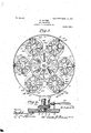
- Fig. 8 is a top plan view with the roof or cover removed.
- Fig. 4 is a detail section showing the lower bearing of the central shaft.
- Fig. 5 is a top plan view of the socketed head receiving the upper end of the central shaft.
- Fig. 6 is avertical section through the rotary head, its supporting-collar, and the hub ofthe gear-ring.
- FIG. 7 is a similar view through one of the cross-arms, showing the bearing for the u per end of one of the seat-spindles and thelliub of the gear which operates the s indles.
- Fig. 8 is a horizontal cross-section t ough one of the seat-supporting spindles and a top plan view of the bearing-head for the gear carried thereby, the said section being taken on line 8 8.of Fig. 7.
- Fig. 9 is a similar' view taken on line 9 9 of Fig. 6.
- Fig. 10 is a vertical section throughl one of the seat-platforms, the cross-piece of the supporting-frame thereof, and the bearing for the lower end of the seat-spindle; and
- Fig. 11 is a detail perspective view of one of the brackets for securing the radial 'cross arms and braces to the frame-ring.
- the numeral 1 designates the central shaft of the apparatus, which is provided at its lower end with a conical journal 2, arranged to turn within a bearing-box 3, fitted within a suitable foundationplate 4, antifriction-bearing balls 5'being interposed between the journal and wall ofthe box to adapt the shaft to turn easily therein.
- the shaft has a Krectangular upper end 6*, Which ts within a correspondingly-shaped socketed head 7, supporting the crown of the canopy roof or cover 8.
- the head 7 is formed withwpairs of spaced ears I9, projecting radially from the periphery thereof, and rigidly attached to these ears are the inner ends of bracing bars or rods 10, which extend outwardly and downwardly from the head and are attached at their outer ends to a framering 11 by means of attaching-brackets 12.
- the ring 11 is provided at each point ⁇ of attachment of a .bracket 12 thereto with an inward oHset 13, forming an exterior recess to receive the body portion of the bracket, which is provided with laterallyrojecting apertured ears 14 for the passage of) fastenings securing it to the offset portion 13.
- Each bracket 12 is also provided with an upwardly-extending arm 15, projecting above the offset portion 13 and ormed with inwardly-projecting s aced ears 16, to which the outer end of the race 10 is bolted or otherwise attached.
- this bearing-support comprises a supportingcollar 2 1, provided with an upwardly-extending bushing-sleeve 22, loosely surrounding the shaft and to the upper end of which is keyed, asindicated at 23, the hub 24 of a gear-ring 25, which effects the simultaneous rotation of the seats and. their supportinglatforms, as hereinafter described.
- the ower face of the rotary head 20 and upper face ofthe collar 21 are grooved to form a vraceway 26 for the reception of bearing-balls 27, while the upper face of the head and lower face of the hub 24 are correspondingly grooved to form a raceway 28 for the reception of b ⁇ earing-balls'29, thus forming a dou- ,ble ball-bearing support for the head 20 to enable it to rotate with a minimum degree of shaft.
- Thesupporting-collar 21 is provided with depending arms or ears 30 for the attachment of the upper ends of upright braces or standards 32, which are fixed at their lower ends to the foundation-plates 4, thus rigidly supporting the collar and gear-ring 25 Iolo vfriction about the support on the central v in position. It will thus be seen that the shaft 1, collar 21, and standards 32 form a rigid supporting structure, while the head 7, braces 10, ring 11, and cross-arms 18 form a rotaryframe whichrevolves about said structure and with the central shaft.
- the cross-arms 18 support a series of rotary platforms 33, each carrying one or more dummies or seats 34.
- each platform 33 is rigidly connected with a supporting-spindle 35, which spindle passes downward through a flanged sleeve 36', fitted in a central opening in the platform and suitably secured thereto and keyed or otherwise rigidly fiXed to the spindle, as by means of setscrews 36.
- a cross-piece 37 suspended from the overhanging cross-arm 18 by hanger-rods 38, and below the sleeve 36 this cross-piece is formed with an opening through which the lower end of the spindle projects.
- the spindle terminates at its lower end in a conical head or journal 39, which turns within a bearing-block 40, flanged for the passage of bolts 41, securing it to the cross-piece.
- Bearing-balls 42 are arranged in this box to permit the journal 39 to turn easily therein.
- the cross-piece 37'and hangers 33 form a supporting-frame in which the lower end of the spindle35 is journaled and thatthe platform 33 is rigidly connected to the spindle to rotate therewith.
- the upper ends of the outer hangers 38 pass through the arms 17 of the brackets 12 and outer endsof'the cross-arms 18 and are provided with nuts to secure the same together, thus dispensing with the use of auxiliary and independent sets of fastenings.
- each spindle 35 is journaled in a bearing-sleeve 43, carried by the cooperating cross-arm 13, and this sleeve is formed at its upper end with a bearing plate or head 44.
- the spindle 35 has a rectangular extremity 45, fitting within a corresponding socket in the hub 46 of a gear-wheel 47, meshing with the gear-ring 25, the meeting faces of said bearing plate or head and hub being grooved to form a raceway 43 for the reception of bearing-balls 49 to adapt the spindle and gear-wheel to rotate with a minimum amount of friction.
- each cross-arm 13 is preferably formed of sections 18l and 18h, attached, respectively, at their inner and outer ends to the rotary-head 20 and frame-ring 11 and formed at their proximate ends with tenons or reduced extensions 18C, fitting within sockets 50, carried by the bearing-sleeve 43 'and rigidly fastened therein by bolts or rivets 51.
- the gear-wheels 47 of all the spindles 35 are arranged annularly between the gearring 25 and frame-ring 1 1 andv mesh with said gear-ring, whereby as the rotating frame revolves with' the central shaft 1 motion will be communicated to all the spindles to rotate the several seat or dummy supporting platforms 33, thus providing an apparatus in which independent rotation is imparted to the seats as the apparatus as a whole rotates, thus giving a waltzing effect during the operation of the apparatus.
- the central shaft 1 may be rotated by any approved type of driving means.
- I have shown it provided at its lower end with a miter-gear 52, meshing with a similar gear 53 on a drive-shaft 54, which may receive motion from any suitable source of power.
- tionary frame a stationary gear element upon the stationary frame, a rotary frame connected with the shaft and head, a series of seat-supportingfspindles carried by the rotary frame, and *gears carried by said spindles meshing with the stationary gearupon the stationary frame, whereby the spindles are rotated in unison from and about the stationary frame as the rotary frame revolves.
- va central shaft a stationary frame having a bearing 'disposed about the upper portion of the shaft, a stationary gear supported by the frame above said bearing, a collar rotatable on said bearing, 'a rotary frame connected vwith the central shaft and collar, spindles on the rotary frame, and gears carried by said spindles and meshing with said stationary gear.
- a central shaft In a roundabout, a central shaft, a stationary frame provided with a supporting portion, a bearing disposed about the upper portion of the shaft, a rigid gear carried by said supporting portion, a revoluble collar supported by said bearing, avrotary frame connected with the shaft and collar, a series of seat-supporting spindles carried by the ro- 'carrie tary'frame, and gears carried by said spindles meshing with the stationary gear.
- a central shaft In a roundabout, a central shaft, astationary frame, a rotary head on the stationary frame, a frame-ring, cross-arms connecting the rotary head with the frame-ring, each of said cross-arms being composedof two sections, couplings connecting the sections and provided with bearing-sleeves and bearingheads, seat-supporting spindles journaled at their u per ends in said bearing-sleeves, gears dl.j by 'said spindles, antifriction-bearings between said gears and the bearingheads, and a fixed gear carried by the stationaryframe and meshing with said spindles.
Landscapes
- Rolling Contact Bearings (AREA)
Description
" G. LEINBRT.
RoUNDAB0UT. APPLICATION FILED APR! 22, 1905.V
, No. 815,103. PATBNTED MAR. v.13, '1906.
PATENTB MAIL-13, 1906. -G.LB1NBRT n ROUNDABOUT.-
APPLIOATION FILED Amma, 1905.
va SHEETS-SHEETS.
' l "W" gil/Z; r A l.
'GUSTAV LEINERT, vOF BROOKLYN, NEW YORK.
l i RouNDABou-r. i
Specification of. Letters Patent.
Patented Mafeh 13, 1906.
Application filed April 22, 1905. -Serial No. 256 ,943.
To all whom it may concern:
Be it known that I, GUsTAv LEINERT, a citizen of the United States, residing at Brooklyn, in the county of Kings and State of New York, have invented new and useful Improvements in Roundab outs, of which the following is a specification.
This 1'nvention relates to pleasure appara-'l tus of that class known as carousels, merry-go-rounds, or roundabouts, the object of the invention being to provide a device of this class in which independent rotation is imparted to the seats or dummies as the apparatus as a whole rotates and inwhich the parts are constructed, combined, and arranged to produce an ap aratus of maximum simplicity, strength, an durability.
, With this and other objects in view the invention consists of the construction and combination of parts hereinafter fully described and claimed, reference being had to the accompanying drawings, in which- Flgure 1 is a vview in elevation of a roundabout embodying my invention. Fig.v 2 is a substantially vertical transverse section of the same. Fig. 8 is a top plan view with the roof or cover removed. Fig. 4 is a detail section showing the lower bearing of the central shaft. Fig. 5 is a top plan view of the socketed head receiving the upper end of the central shaft. Fig. 6 is avertical section through the rotary head, its supporting-collar, and the hub ofthe gear-ring. Fig. 7 is a similar view through one of the cross-arms, showing the bearing for the u per end of one of the seat-spindles and thelliub of the gear which operates the s indles. Fig. 8 is a horizontal cross-section t ough one of the seat-supporting spindles and a top plan view of the bearing-head for the gear carried thereby, the said section being taken on line 8 8.of Fig. 7. Fig. 9 is a similar' view taken on line 9 9 of Fig. 6. Fig. 10 is a vertical section throughl one of the seat-platforms, the cross-piece of the supporting-frame thereof, and the bearing for the lower end of the seat-spindle; and Fig. 11 is a detail perspective view of one of the brackets for securing the radial 'cross arms and braces to the frame-ring.
Referring to the drawings, the numeral 1 designates the central shaft of the apparatus, which is provided at its lower end with a conical journal 2, arranged to turn withina bearing-box 3, fitted within a suitable foundationplate 4, antifriction-bearing balls 5'being interposed between the journal and wall ofthe box to adapt the shaft to turn easily therein. The shaft has a Krectangular upper end 6*, Which ts within a correspondingly-shaped socketed head 7, supporting the crown of the canopy roof or cover 8. The head 7 is formed withwpairs of spaced ears I9, projecting radially from the periphery thereof, and rigidly attached to these ears are the inner ends of bracing bars or rods 10, which extend outwardly and downwardly from the head and are attached at their outer ends to a framering 11 by means of attaching-brackets 12. As shown in Figsj yand 11, the ring 11 is provided at each point `of attachment of a .bracket 12 thereto with an inward oHset 13, forming an exterior recess to receive the body portion of the bracket, which is provided with laterallyrojecting apertured ears 14 for the passage of) fastenings securing it to the offset portion 13.- lEach bracket 12 is also provided with an upwardly-extending arm 15, projecting above the offset portion 13 and ormed with inwardly-projecting s aced ears 16, to which the outer end of the race 10 is bolted or otherwise attached.
Secured at their outer ends to arms 17, projecting inwardly beneath the ring 1 1 from the bracket.12, are a series of radial crossarms 18, which are attached at their inner ends to ears 19, projecting from a head 20, arranged to rotate upon a bearing-support encompassing the central shaft 1. As shown, this bearing-support comprises a supportingcollar 2 1, provided with an upwardly-extending bushing-sleeve 22, loosely surrounding the shaft and to the upper end of which is keyed, asindicated at 23, the hub 24 of a gear-ring 25, which effects the simultaneous rotation of the seats and. their supportinglatforms, as hereinafter described. The ower face of the rotary head 20 and upper face ofthe collar 21 are grooved to form a vraceway 26 for the reception of bearing-balls 27, while the upper face of the head and lower face of the hub 24 are correspondingly grooved to form a raceway 28 for the reception of b`earing-balls'29, thus forming a dou- ,ble ball-bearing support for the head 20 to enable it to rotate with a minimum degree of shaft.l Thesupporting-collar 21 is provided with depending arms or ears 30 for the attachment of the upper ends of upright braces or standards 32, which are fixed at their lower ends to the foundation-plates 4, thus rigidly supporting the collar and gear-ring 25 Iolo vfriction about the support on the central v in position. It will thus be seen that the shaft 1, collar 21, and standards 32 form a rigid supporting structure, while the head 7, braces 10, ring 11, and cross-arms 18 form a rotaryframe whichrevolves about said structure and with the central shaft.
The cross-arms 18 support a series of rotary platforms 33, each carrying one or more dummies or seats 34. As shown, each platform 33 is rigidly connected with a supporting-spindle 35, which spindle passes downward through a flanged sleeve 36', fitted in a central opening in the platform and suitably secured thereto and keyed or otherwise rigidly fiXed to the spindle, as by means of setscrews 36. Below the platform 33 is earranged a cross-piece 37, suspended from the overhanging cross-arm 18 by hanger-rods 38, and below the sleeve 36 this cross-piece is formed with an opening through which the lower end of the spindle projects. The spindle terminates at its lower end in a conical head or journal 39, which turns within a bearing-block 40, flanged for the passage of bolts 41, securing it to the cross-piece. Bearing-balls 42 are arranged in this box to permit the journal 39 to turn easily therein. It will thus be seen that the cross-piece 37'and hangers 33 form a supporting-frame in which the lower end of the spindle35 is journaled and thatthe platform 33 is rigidly connected to the spindle to rotate therewith. Preferably the upper ends of the outer hangers 38 pass through the arms 17 of the brackets 12 and outer endsof'the cross-arms 18 and are provided with nuts to secure the same together, thus dispensing with the use of auxiliary and independent sets of fastenings.
The upper end of each spindle 35 is journaled in a bearing-sleeve 43, carried by the cooperating cross-arm 13, and this sleeve is formed at its upper end with a bearing plate or head 44. The spindle 35 has a rectangular extremity 45, fitting within a corresponding socket in the hub 46 of a gear-wheel 47, meshing with the gear-ring 25, the meeting faces of said bearing plate or head and hub being grooved to form a raceway 43 for the reception of bearing-balls 49 to adapt the spindle and gear-wheel to rotate with a minimum amount of friction. As shown in detail in Fig. 7, each cross-arm 13 is preferably formed of sections 18l and 18h, attached, respectively, at their inner and outer ends to the rotary-head 20 and frame-ring 11 and formed at their proximate ends with tenons or reduced extensions 18C, fitting within sockets 50, carried by the bearing-sleeve 43 'and rigidly fastened therein by bolts or rivets 51. The gear-wheels 47 of all the spindles 35 are arranged annularly between the gearring 25 and frame-ring 1 1 andv mesh with said gear-ring, whereby as the rotating frame revolves with' the central shaft 1 motion will be communicated to all the spindles to rotate the several seat or dummy supporting platforms 33, thus providing an apparatus in which independent rotation is imparted to the seats as the apparatus as a whole rotates, thus giving a waltzing effect during the operation of the apparatus.
From the foregoing description, taken in connection with the accompanying drawings, the construction and mode of operation of my improved roundabout will be readily understood, and it will be seen that it provides an apparatus of this character which imparts independent rotation to the seat-supports in an effective manner and in which the parts are constructed, combined, and arranged to produce an apparatus of maximum simplicity, strength, and durability.
The central shaft 1 may be rotated by any approved type of driving means. In the present instance I have shown it provided at its lower end with a miter-gear 52, meshing with a similar gear 53 on a drive-shaft 54, which may receive motion from any suitable source of power.
I-Iaving thus described the invention, what is claimed as new isj 1. In a roundabout, the combination of a central shaft, a rotary frame supported thereby and turning therewith, a station ary bearing supported about the upper end of the shaft, a gear-ring rigidly connected with said bearing, a rotary head turning on said bearing and connected with the rotary frame, a series of seat-supports carried by the rotary frame, spindles journaled in said seat-supports and rotary frame, and ears attached to the upper ends of the spindles and meshing with the gear-ring.
2. In a roundabout, the combination of a central shaft, a stationary bearing arranged about the upper end of said shaft, a gear-ring rigidly connected with the stationary bearing, a rotary head journaled on the stationary bearing, a rotary 'frame connected with the shaft and rotary head, spindles journaled in said rotary frame, gears carried by the spindles and meshing with the gear-ring, and seat-supports carried by said spindles.
3. In a roundabout, the combination of a central shaft, a rigidy supporting-frame carrying a supporting-collar arranged about the upper end of the shaft, a rotary head mounted on said collar, a rotary frame connected to and supported by the central shaft and rotary head, seat-supporting frames hung from the rotary frame, spindles journaled in the rotary frame and seat-supporting frame and carrying gears at their upper ends, seats connected l with the spindles to rotate therewith, and a gear-ring fixed to sai d supporting-collar and meshing with the spindle-gears.
4. In a roundabout, the combination of a central shaft, a stationary frame, a collar arranged about the upper end of the shaft and supported by said frame, a gear-ring rigidl IOO to the upper end of the shaft, braces connect'- connected with the collar, a head arranged to rotate upon the collar and between the same and the gear-rin a rotary frame supported by the shaft, an head, seat-supports, spindles carrying the same and journaled upon the rotary frame, and gears upon the upper ends of the spindles and meshing with the rigid gear-ring. Y
-5. In a roundabout, the combination of a central shaft, a stationary frame, a collar arrangedabout the upper end of theshaft and supported by said frame, a gear-ring fixed to the collar, a rotary head mounted upon the collar and between the same and the earring, a frame-ring, a supporting element ed ing said supporting element-with the framering, cross-arms connecting the rotary head with the frame -ring, a series of pendent frames supported from the cross-arms, spindles journaled at their lower ends in the pendent frames and at their upper ends upon the cross-arms, seat-supports carried by the spin' dles, and gears upon the upper ends of the spindles meshing with the gear-ring.
6. In a roundabout, a central shaft, a stationary frame, a rotary head upon the stagear.
tionary frame, a stationary gear element upon the stationary frame, a rotary frame connected with the shaft and head, a series of seat-supportingfspindles carried by the rotary frame, and *gears carried by said spindles meshing with the stationary gearupon the stationary frame, whereby the spindles are rotated in unison from and about the stationary frame as the rotary frame revolves.
7. Ina roundabout, va central shaft, a stationary frame having a bearing 'disposed about the upper portion of the shaft, a stationary gear supported by the frame above said bearing, a collar rotatable on said bearing, 'a rotary frame connected vwith the central shaft and collar, spindles on the rotary frame, and gears carried by said spindles and meshing with said stationary gear.
8. In a roundabout, a central shaft, a stationary frame having a bearing portion, and a bushing surrounding the upper portion of the shaft, a stationary `gear fixed to said bushin a collar rotatable between the bearing an gear and about the bushing, a rotary frame connected with the shaft and collar, a series of seat-supporting spindles carried by the rotary frame, and gears carried by said spindles and meshing with said stationary 9. In a roundabout, a central shaft, a stationary frame provided with a supporting portion, a bearing disposed about the upper portion of the shaft, a rigid gear carried by said supporting portion, a revoluble collar supported by said bearing, avrotary frame connected with the shaft and collar, a series of seat-supporting spindles carried by the ro- 'carrie tary'frame, and gears carried by said spindles meshing with the stationary gear. l
10. In a roundabout, a central shaft, a stationary frame, a rotary head upon the stationary frame, a frame-ring, sectional crossarms connected with the rotary head and frame-rin coupling members connecting the sections o the cross-arms'and provided with bearings, seat-supporting spindles journaled at their upper ends in said bearings, gears carried by said spindles, and a fixed gear upon the stationary frame for communicating motion to said spindles.
11. In a roundabout, a central shaft, astationary frame, a rotary head on the stationary frame, a frame-ring, cross-arms connecting the rotary head with the frame-ring, each of said cross-arms being composedof two sections, couplings connecting the sections and provided with bearing-sleeves and bearingheads, seat-supporting spindles journaled at their u per ends in said bearing-sleeves, gears dl.j by 'said spindles, antifriction-bearings between said gears and the bearingheads, and a fixed gear carried by the stationaryframe and meshing with said spindles.
12. AIn a roundabout, a central shaft, a stationary. frame, a rotary head upon the stationary frame, a rotary frame connected with the shaft and head, a fixed gear carried by the stationary frame, rods depending from the supporting frame and carrying crosspieces provided with openings, bearing-sock-v ets disposed upon the cross-pieces below said openings, seat-supporting spindles journaled at their upper ends in the rotary frame and at their `lower ends in said sockets, antifriction-bearings for the j ournaled portions of the spindles, and gears upon the upper ends of vportions fixed to the frame-ring, inwardlyextending arms connected with said crossarms, and also having portions projecting above the frame-ring and provided with ears, braces between the sleeve or socket and ears of the bracket, a stationary gear upon the stationary frame, a series of seat-supporting spindles ,jou'rnaled in the rotary frame, and
Agears carried by vsaid spindles kand meshing with said stationary gear.
In testimony whereof I aflix my signature in presence of two witnesses.
- GUSTAV LEINERT. Witnesses: l F. J. GREIFENSTEIN ELIZABETH LEINERT.
IOO
vthe spindles meshing with said stationary
Priority Applications (1)
| Application Number | Priority Date | Filing Date | Title |
|---|---|---|---|
| US25694305A US815103A (en) | 1905-04-22 | 1905-04-22 | Roundabout. |
Applications Claiming Priority (1)
| Application Number | Priority Date | Filing Date | Title |
|---|---|---|---|
| US25694305A US815103A (en) | 1905-04-22 | 1905-04-22 | Roundabout. |
Publications (1)
| Publication Number | Publication Date |
|---|---|
| US815103A true US815103A (en) | 1906-03-13 |
Family
ID=2883584
Family Applications (1)
| Application Number | Title | Priority Date | Filing Date |
|---|---|---|---|
| US25694305A Expired - Lifetime US815103A (en) | 1905-04-22 | 1905-04-22 | Roundabout. |
Country Status (1)
| Country | Link |
|---|---|
| US (1) | US815103A (en) |
-
1905
- 1905-04-22 US US25694305A patent/US815103A/en not_active Expired - Lifetime
Similar Documents
| Publication | Publication Date | Title |
|---|---|---|
| US815103A (en) | Roundabout. | |
| US946639A (en) | Rotary swing. | |
| US1050567A (en) | Rotary passenger-carrier. | |
| US546912A (en) | Display apparatus | |
| US1896796A (en) | Roundabout | |
| US890558A (en) | Amusement device. | |
| US843908A (en) | Carousel. | |
| US1839509A (en) | Roundabout | |
| US563894A (en) | Pleasure-wheel | |
| US1179232A (en) | Roundabout. | |
| US994444A (en) | Roundabout. | |
| US1186353A (en) | Motor. | |
| US157311A (en) | Improvement in revolving pleasure-carriages | |
| US1028418A (en) | Combination clothes-line and merry-go-round. | |
| US820339A (en) | Merry-go-round. | |
| US916680A (en) | Apparatus for gymnastic work. | |
| US857903A (en) | Amusement apparatus. | |
| US573577A (en) | Carousel | |
| US850973A (en) | Quadruplex cycle. | |
| US1053100A (en) | Roundabout. | |
| US515088A (en) | Wilhelm mtjmbrauer | |
| US715985A (en) | Wind-motor. | |
| US1047149A (en) | Toy carousel. | |
| US410301A (en) | Merry-go-round | |
| US1761895A (en) | Merry-go-round |