US1761895A - Merry-go-round - Google Patents
Merry-go-round Download PDFInfo
- Publication number
- US1761895A US1761895A US233199A US23319927A US1761895A US 1761895 A US1761895 A US 1761895A US 233199 A US233199 A US 233199A US 23319927 A US23319927 A US 23319927A US 1761895 A US1761895 A US 1761895A
- Authority
- US
- United States
- Prior art keywords
- merry
- round
- floor
- secured
- sections
- Prior art date
- Legal status (The legal status is an assumption and is not a legal conclusion. Google has not performed a legal analysis and makes no representation as to the accuracy of the status listed.)
- Expired - Lifetime
Links
- 230000033001 locomotion Effects 0.000 description 11
- 238000009408 flooring Methods 0.000 description 6
- 210000005069 ears Anatomy 0.000 description 5
- 238000005096 rolling process Methods 0.000 description 4
- 239000002184 metal Substances 0.000 description 3
- 238000009413 insulation Methods 0.000 description 2
- 230000001788 irregular Effects 0.000 description 2
- 241001465754 Metazoa Species 0.000 description 1
- 206010028980 Neoplasm Diseases 0.000 description 1
- 238000005266 casting Methods 0.000 description 1
- 229940000425 combination drug Drugs 0.000 description 1
- 239000004020 conductor Substances 0.000 description 1
- 238000010276 construction Methods 0.000 description 1
- 230000000694 effects Effects 0.000 description 1
- 238000005286 illumination Methods 0.000 description 1
- 238000009434 installation Methods 0.000 description 1
- 238000012986 modification Methods 0.000 description 1
- 230000004048 modification Effects 0.000 description 1
- 230000002093 peripheral effect Effects 0.000 description 1
- 230000003014 reinforcing effect Effects 0.000 description 1
- 230000000284 resting effect Effects 0.000 description 1
- 239000000725 suspension Substances 0.000 description 1
Images


Classifications
-
- A—HUMAN NECESSITIES
- A63—SPORTS; GAMES; AMUSEMENTS
- A63G—MERRY-GO-ROUNDS; SWINGS; ROCKING-HORSES; CHUTES; SWITCHBACKS; SIMILAR DEVICES FOR PUBLIC AMUSEMENT
- A63G1/00—Roundabouts
- A63G1/24—Roundabouts with seats performing movements in a horizontal plane, other than circular movements
-
- A—HUMAN NECESSITIES
- A63—SPORTS; GAMES; AMUSEMENTS
- A63G—MERRY-GO-ROUNDS; SWINGS; ROCKING-HORSES; CHUTES; SWITCHBACKS; SIMILAR DEVICES FOR PUBLIC AMUSEMENT
- A63G1/00—Roundabouts
- A63G1/30—Roundabouts with seats moving up-and-down, e.g. figure-seats
Definitions
- Thisinventi-on is concerned with amusement apparatus of the type commonly known asmerry-go-rounds, and is designed to produce a device of the class described in which the passenger, instead of merely riding around and around in a circle, shall movein different ellipsoidal paths, the relative lengths of the axes of which may be varied, if desired,1by changing the relative speeds of the two driving gearings which I employ to secure the desired movement of translation.
- I To this end I mount af'merry-go-round on wheels rolling over a floor, which merry-goround' is simultaneously rotated about its axis as a center,” andhas its center in turn given a movement of' translation in a circle, so that while the merry-go-round as a whole moves in a circle, the individual passengers are moved, as abovestated, through different ellipsoidal paths covering different parts of the floor.
- amerry-go-.round in which the passengers, instead of having their seats merely raised and lowered as they are translated, as is the common practice, have the seats tilted, preferably-at irregular and unexpected intervals, to add a variety to p the movements to which they are subjected.
- My invention is further concerned with a structure of the type first described in which an electric circuit may be maintained in the merry gO-ro-und proper in spite of the irregular movement of translation to which it is subjected. f i
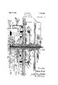
- Fig. 1 is a top plan view, partly in section, on the line 1-1 of Fig. 2, showing a portion of the complete apparatus;
- Fig. 2 is a vertical section of a portion of said apparatus, as seen on the line 2-2 of Fig. 1, but on a somewhat larger scale;
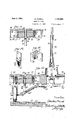
- Fig. 3 is a detail, partly in section, showing 6 how the temporary floor is quickly secured on the supporting trestles;
- Fig. 4 is a view in section on the line 4-4 of Fig. 3; I
- Fig. 5 is a central vertical section, on a much enlarged scale, through the driving gearing located at the center of the floor;
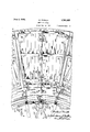
- Fig. 6 is an inverted plan view of an outer portion of the merry-go-round, showing one of the tilting sections and its connections;
- Fig. 7 is an inverted plan view which may be considered as a continuation of Fig. 6, and shows the driving gearing for translating the merry-go-round as'a whole through a circle;
- Fig.8 is a plan view of a partion of the center of the merry-go-round, with the upper hub disk removed;
- Fig. 9 is a top plan view of the same portion of the structure as is seen in Fig. 8, but with the top hub disk in place; 8
- Fig. 10 is a detail in vertical section through the center of the lower portion of the Inerry-go-round, but on a larger scale;
- FIG. 11 is a perspective view of the inner end of one of the spokes of the merry-goround;
- Fig. 12 is a perspective view of one of the plates employed on the spokes
- Fig. 13 is a central vertical section, on the same scale as Fig. 10, showing the connections between the inner, relatively-stationary portion of the merry-go-round and the tilting sections at its periphery;
- V Fig. 14 is an enlargeddetail in section on the line 141& of Fig. 6;
- Fig. 15 is a perspective view of one of the bearing plates seen in Fig. 14;
- Fig. 16 is a similar .view of one of' the hinge eeiine'etions likewise seen. iii said Fig. l l: I
- Figs. 1 to 4 For the portable floor structure, I preferably employ the arrangement shown in Figs. 1 to 4, where the fioorproper is shown as made up of segmental sections 20, preferably consisting of two layers 21 and 22 of tongued andgrooved boards laid crosswise with the central portion where most of the wear comes covered with the sheet-metal surface 23 which "forms the track for the caster wheels of the merry-go-ronnd during much of their move ment.
- Thesethree layers are suitably nailed or bolted together and are supported by numerous trestles'24, extending in various directions, and eachof which is longenough to support all or a part or a plurality of sec tions 20, so that'when all'of'thesections29 are clamped upon the trestles 2 4, a rigid and generally levelfloor surface s secured.
- These toggle clamps are.
- I preferably jmake. the flooring with anirregular' surface and preferably changeable in its irregularity, and for this purpose I providethe sections 20'with the" plural seriesv offour recesses 31adaptd 'to receive the four pinsv 32 of the humps'33,
- the base offthe merry-go-round proper 7 preferably constructed as shown in Figs. 1,
- the spoke has the large hole 41 extending therethrough-and adapted to receive the lug 42 "projecting upwardly J from the upper surface of the bottom hub "through the registering holes formed in the V so disk 48, and the' similar lug 44 projecting downwardly from the under surfacexof the top hub disk'45.
- the bottom hub disk43 has; the upwardly eXtendingfianges 46*forming r recesses inwhich the upper enjds'ofzthe.
- spokes 34 fitsnugly and are heldlinplace by the action of the lugs 42 and 44 when the two disks 43 and 45' are rigidly secured to- I gether by the bolts 47 passing therethrough in the space between thespokes.
- This structure permits of thefeasy dismantling of the 7 wheel into pieces that can be easily handled V 7 when it is desired .to transfer the merry-go- 7 round to anew location.
- the hollow cena ter pole 48 is located bylhaving its bottom stepped in' thecentrally'jlocated' circular aperture in the casing 49, which hasthe pair of ears 5O project1ng upwardly therefrom. 'andadapted' to fit between the two pair of:
- the cente'r pole supports a canopy of any suitable'construction, which preferably has the upper -wheelstructure, with similartop and bottom hub d sks 58 and 5 9 or a single casting secured to the center pole positioning andsupporting.
- a canvas top 64 will be supported in any desired manner.
- I preferably provide the incandescent lights .65 secured on the under side of each of the upper spokes'60, and all around the inner side of the cornice 63, and Iprovide for a circuit cooperating therewith in' all positions of the merry-go-round-by the electrical connections to'be hereinafter described.
- central. wheel 66 (see Fig. 10) has the upper end of its fork 67 journaled in a bearing 68 formed in the center of the bottom hub disk 13, it preferably being provided with the collar orflange 69 engaging the bottom of the bearing. J ourna-led in a suitable bearing 70 (see Fig. 13) secured at the centeron the inner side of each of the tie beams 35 is the fork of the caster wheel 71, and near the two outer corners of each of the segmental pe- .ripheral portions 72 of the merry-go-round is secured the bearing 73 for the fork of the caster wheel 7 4 (see'Fig.
- the bearings 73 being preferably secured on the inner face of the outer tie or frame beam 75, which is connected by the hinge plates 36 to the radial beams 76, which at their inner ends are similarly connected to the inner tie beams 77.
- Additional tie beams 78 and 79, intermediately'loc-ated and similarlysecured, are employed'to give additional strength to the sec tional frames 72 and to furnish supports for the bearings 80, 81 and 82 of the crank shaft 83 journaled therein and connected by the telescoping universal joint 84 with the shaft of the wheel 71, so that as the latter rolls overthe floor 20 the crank shaft 83 will be rotated.
- the beams 75, 76,77, 78 and 79 have the flooring boards 84 secured thereon, which flooring is provided with the plurality of apertures 85, through which extend the links86journaled at their lower ends on the cranks 87 and having their upper ends pivoted tojthe vertical actuating rods 88 extending up through the hollow metal standards 89, preferably-detachably secured to the floor 84c and having their upper ends 90 re depictd to a tubular form'to furnish a substantial; close-fitting bearin ifor the rods 88, which have theseats91 which may take the form of horses or other animals) removably secured thereon so that they cannotrotate onthe rods 88, which in turn are prevented from any tendency to rotate by the pin 92 projecting therefrom and engaging the elongated, longitudinallyextending, vertical slot 93 in the upperend 90 of the standard 89.
- the plates 96 and 97 are secured at their upper ends in recesses cut in the supporting beams 35, (0 and 77 by the bolts 99 having their heads countersunk in the plates. It will be obvious that these plates and anti-friction rollers will materially reduce the friction, as well as the noise, which would otherwise result from the tilting or relative movement of the outer sections 72.
- the disk 101 Beneath the floor is the disk 101 having the downwardly-extending radial ribs 102 supporting at their outer ends the annulus 103, through apertures in which extend the supporting pins 104 of the customary brake band 105, which is normally held out of contact with the periphery of the brake disk 106 by the helically-coiled expanding springs 107 interposed between the washers 108 on the out-er ends of the pins 104 and the annulus 103.
- the customary brake lever (not shown) will be provided to tighten the brake band 105 on the disk 106 to stop the merry-go-round when the power has been shut off.
- the two disks 100" and 101 are bolted to the floor by the bolts 109 passed through them and the floor, the nuts 110 of which may be held in the recesses 111 formed for that purpose in the ribs 102.
- J ournaled in the bearing sleeve 100 is the hollow shaft 112 having the drive wheel 113 secured on its lower end, and the enlarged rectangular upper end 114 resting and turning on the top of the sleeve 100.
- the brake disk 106 is also secured to this hollow shaft. As seen in Figs.
- the upper end of the shaft 112 has clamped thereon by the bolts 115 the bars or pieces 116, the outer ends of which form a pair of ears between bolted thereon the block 120, which is 11s bolted in andforming the end or the truss beam or arm 119, best seen in Fig. 7
- This arm 119 is preferably cast in tumor whore sections bolted together, through the 'slots :119 so it can be properly ad usted to secure proper meshing of the spur gear pinion 127 with the rack 124 hereinafter described.
- the outer end of the beam 119 has pivoted by the'bolt 121 between the ears 122 forming a part of the split bearing block 123, 'which forms a journal bearing for the pint-le of the forks 67 of the Wheel 66 below the collar 69 (see Fig. 10).
- a circular rack 124 Bolted on the under sides of the sweeps or spokes 34 near their outer ends is a circular rack 124, which is preferably made in sections, for ease of transportation when dis- 'mantled.
- Journaled inside of the hollow shaft 112 is a preferably hollow shaft 125 having the driving wheel 126 secured on its lower end, and having the spur gear pinion 127 meshing with the rack 124 secured on its upper end.
- the shaft 125 is rotated, the merry-gdround proper will be rotated about its center as an axis.
- the electrical connections for the lamps cannot be main tained by ordinary means, and to furnish con tacts for a complete circuit, 1 place in the hollow shaft aconductor rod 129 protected'by insulation 130, and preferably enclosed in a tube 131, the lower end of which is secured in and supported by the bracket 132 secured to the under side of the floor.
- This bracket 132 is reinforced by the two sim ilar'bra'ckets' l32 and 132 extending at right angles thereto, the bracket 132 being seen only in cross section in Fig. 5.
- One or more roller bearings 133 may be interposed between the tube 131 and the hollow shaft 125.
- the upper end of the rod 129 is enlarged to form a contact disk 134, which is always engaged by'some portion of a concentric, circular conductor-rod 135 supported and insulated from the under side of the sweeps or spokes 34in the manner clearly shown in Fig. 5.
- a lead or leads may be taken from any point of the conductor ring 135 to form the necessary circuit or circuits for the lamps 65, and the return lead or leads (not shown) will be connected to the slightly'larger contact ring 136 supported by thejarms 137 from the insulation blocks 138, which in turnare secured to the under side ofthe spokes 34.
- tact ring 136 will alwayseng'age tliesmaller contact ring 139 concentric withthe driving shafts for and supported by theblocks- ⁇ 140 of insulating materialsecured'upon' the floor.
- the return line not shown) will be taken from the ring 139, so that by connecting therod'129 and the ring 139 with the positive.
- the power is first turned on to the'spur gear pinionand therotation of the merry-go-round is'started, and when it is up to, say, half speed, power'is applied to the arm 119 to give the merry-go-round its movement of translation.
- the speed of the spur gear may be 7 increased, and'the relative speeds varied as.”
- the comb-ination with a floor, of a merry-go-round having a relatively fixed central portion and hinged outer sections movable over the floor, means for simultaneously rotating said merry-goround on its vertical axis and translating it bodily over the floor and humps on the floor to tilt the hinged sections at different times in different rotations.
- a rotatable merry-goround made up of a central portion and outer hinged sections, gearing for simultaneously rotating said merry-go-round on its vertical axis and translating it bodily over the floor, and humps on the floor to tilt the hinged sections at different times in different rotations.
- a hollow driving shaft journaled in the floor having an arm pivotally connected at one end with the center of the merry-go-round, a second hollow shaft inside of the first having a pinion meshing with the circular rack, means for rotating said driving shafts, a vertical electrical contact member extending up through the inner shaft and terminating in a circular contact, an annular contact within the circular rack carried by the merry-go-round and engaging the upper end of the Vertical contact member, another annular contact member outside of the rack bar, and a third annular contact member surrounding the bearing and engaging the outer annular contact member carried by the merry-go-round.
- the combinawith a floor having substantially circular humps located thereon at various places, of a merry-go-round mounted thereon having vertically movable sections, gearing to rotate said merry-go-round about its vertical axis and to swing said vertical axis in a circle about a stationary axis at the center of the floor, and rolling supports extendingfrom the vertically movable sections to the floor so that the humps when encountered by I the supports approaching them from any angle, will lift the supports.
- the combination with a merry-go-round of means for translating it bodily and simultaneously rotating it, a plurality'of passenger-supporting sections movable up and down relative to the main central portion thereof, and "located toward its periphery, a support over which the merry-go-round is translated, and substan tially circularhumps located on said support to lift said sections when contacted there- 7
- a plurality'of passenger-supporting sections movable up and down relative to the main central portion thereof, and "located toward its periphery, a support over which the merry-go-round is translated, and substan tially circularhumps located on said support to lift said sections when contacted there- 7
Landscapes
- Toys (AREA)
Description
Ju ne 3, 1930.
w; POWELL 1,761,895
MERRY-GO-ROUND an Nov. 14, 192'? 7 Sheets-Sheet 1 2a a I, a HuIeTJEF;
ar, 4. Ja i W. POWELL MERRY-VGQI-ROUND J June 3, 1930.
' '7 Sheets-Sheet 2 Filed Nov. 14 1927 June 3, 1930.
w. P OWELL MERRY-GO-ROUND Filed Nov. 14. 1927 7 Sheets-Sheet 3 aim w. POWELL MERRY-GO-RdUND June 3, 1930.
7 Sheets-Sheet 4 Filed Nov. 14, 1927 w. POWELL MERRY-GO-ROUND June 3, 1930.
Filed Nov. 14, 1927 7 Sheets-Sheet 5 W. POWELL MERRY-GO-ROUND June 3, 1930.
Filed Nov. 14, 1927 7 Sheets-Sheet 6 W p v w v mmx x% i Mai la s
' Patented June 3, 1930 PATENT OFFICE .WIL'I'ON POWELL, OF PRESCOTT, ARIZONA MERRY-GO-ROUND Application filed Novemberl l, 1927. Serial No. 233,199.
'Thisinventi-on is concerned with amusement apparatus of the type commonly known asmerry-go-rounds, and is designed to produce a device of the class described in which the passenger, instead of merely riding around and around in a circle, shall movein different ellipsoidal paths, the relative lengths of the axes of which may be varied, if desired,1by changing the relative speeds of the two driving gearings which I employ to secure the desired movement of translation. I To this end I mount af'merry-go-round on wheels rolling over a floor, which merry-goround' is simultaneously rotated about its axis as a center," andhas its center in turn given a movement of' translation in a circle, so that while the merry-go-round as a whole moves in a circle, the individual passengers are moved, as abovestated, through different ellipsoidal paths covering different parts of the floor. i It is also concerned with amerry-go-.round in which the passengers, instead of having their seats merely raised and lowered as they are translated, as is the common practice, have the seats tilted, preferably-at irregular and unexpected intervals, to add a variety to p the movements to which they are subjected. To this end, I form the merry-go-round with so its peripheral portions separated into sec tions pivoted by universal joints to the relatively-stationary central portion and. having three-point supports, so that each of said sectionscan tilt when either of the two wheels forming two of the three supports pass over humps placedon the floor wherever they may be desired. i
My invention is further concerned with a structure of the type first described in which an electric circuit may be maintained in the merry gO-ro-und proper in spite of the irregular movement of translation to which it is subjected. f i
My invention is finally concerned with oer tain novel combinations of elements, which I employ in securig the desired results above enumerated, all as will he described at length, and the novel features thereof pointed out in the claims. l
. To illustrate my nvention, anner hereto seven sheets of drawings, in which the same reference characters are used to designate identical parts in all the figures, of which,
Fig. 1 is a top plan view, partly in section, on the line 1-1 of Fig. 2, showing a portion of the complete apparatus;
Fig. 2 is a vertical section of a portion of said apparatus, as seen on the line 2-2 of Fig. 1, but on a somewhat larger scale;
Fig. 3 is a detail, partly in section, showing 6 how the temporary floor is quickly secured on the supporting trestles;
Fig. 4 is a view in section on the line 4-4 of Fig. 3; I
Fig. 5 is a central vertical section, on a much enlarged scale, through the driving gearing located at the center of the floor;
Fig. 6 is an inverted plan view of an outer portion of the merry-go-round, showing one of the tilting sections and its connections;
Fig. 7 is an inverted plan view which may be considered as a continuation of Fig. 6, and shows the driving gearing for translating the merry-go-round as'a whole through a circle;
Fig.8 is a plan view of a partion of the center of the merry-go-round, with the upper hub disk removed;
Fig. 9 is a top plan view of the same portion of the structure as is seen in Fig. 8, but with the top hub disk in place; 8
Fig. 10 is a detail in vertical section through the center of the lower portion of the Inerry-go-round, but on a larger scale;
Fig; 11 is a perspective view of the inner end of one of the spokes of the merry-goround;
Fig. 12 is a perspective view of one of the plates employed on the spokes;
Fig. 13 is a central vertical section, on the same scale as Fig. 10, showing the connections between the inner, relatively-stationary portion of the merry-go-round and the tilting sections at its periphery; V Fig. 14 is an enlargeddetail in section on the line 141& of Fig. 6; a
Fig. 15 is a perspective view of one of the bearing plates seen in Fig. 14; and
' Fig. 16 is a similar .view of one of' the hinge eeiine'etions likewise seen. iii said Fig. l l: I
I While my invention may-be placed permanently in a building, it suspectible of being made portable, and in the hereinafter described embodiment of the same, I have illustrated it as designed with that end in View, the broad features "of novelty being capable of embodiment in either 'a permanent or a portable form.
For the portable floor structure, I preferably employ the arrangement shown in Figs. 1 to 4, wherethe fioorproper is shown as made up of segmental sections 20, preferably consisting of two layers 21 and 22 of tongued andgrooved boards laid crosswise with the central portion where most of the wear comes covered with the sheet-metal surface 23 which "forms the track for the caster wheels of the merry-go-ronnd during much of their move ment. Thesethree layers are suitably nailed or bolted together and are supported by numerous trestles'24, extending in various directions, and eachof which is longenough to support all or a part or a plurality of sec tions 20, so that'when all'of'thesections29 are clamped upon the trestles 2 4, a rigid and generally levelfloor surface s secured.
The trestles .may. be knockdowmandmay have the lengih'or the-legs adjustable to ac-- ingwith'the larger apertures 26in the boards 21, and in assembling the floor, these apertures are placed adjacentthe beams or the trestles 24, so that with the toggle clamp 27 shown'in the expanded, dotted-line position of Fig. 4, the upper hook 28 maybe caught in "the; plate .25, while the lower .hook 29 is in position to be pulled up and caughtin the recessformedin the metal reinforcing plate .25 bolted to the beam of the trestlei24, when I the handle 30is swung downfto the full-dine 7 locking position. These toggle clamps are.
secured to the ends as well as the sides of the beam and will hold the parts-securely together, but they can be easily released when the toggle is broken Forthe purposes-here 'inafter described, I preferably jmake. the flooring with anirregular' surface and preferably changeable in its irregularity, and for this purpose I providethe sections 20'with the" plural seriesv offour recesses 31adaptd 'to receive the four pinsv 32 of the humps'33,
fee
which will he adjust-ed in a y Position n the floor. I
' The base offthe merry-go-round proper 7 preferably constructed as shown in Figs. 1,
and6 to 1O,.whereits centralportion or lower wheel is made up 'of the wooden sweeps: or spokes 34 radiatingfrom the'center and connected at their outer ends by thetie beams 35, 7
to 12, where it will beseen that thetapered ends of the spokes 84 have the recesses 38 cut therein and filled by the metallic plates39,
to which they may be secured by the hinge V plate 36 (see Fig.16), bolted thereto, and from which they may be quickly'detached' for knockdown purposes bywithdrawing the which are held in place by the rivets 40 passed Y spokes and plates. The spoke has the large hole 41 extending therethrough-and adapted to receive the lug 42 "projecting upwardly J from the upper surface of the bottom hub "through the registering holes formed in the V so disk 48, and the' similar lug 44 projecting downwardly from the under surfacexof the top hub disk'45. The bottom hub disk43 has; the upwardly eXtendingfianges 46*forming r recesses inwhich the upper enjds'ofzthe.
As seen in "I1" gs. 2 9 and 10, the hollow cena ter pole 48 is located bylhaving its bottom stepped in' thecentrally'jlocated' circular aperture in the casing 49, which hasthe pair of ears 5O project1ng upwardly therefrom. 'andadapted' to fit between the two pair of:
the'innerends of the top spokes 60, the outerv ends of which are-supported by the two sets" ofrods' 61 and '62 in a'manner which willbej 56 secured on the i readily understood from the drawings. A
a canvas top 64 will be supported in any desired manner. For illumination, I preferably provide the incandescent lights .65 secured on the under side of each of the upper spokes'60, and all around the inner side of the cornice 63, and Iprovide for a circuit cooperating therewith in' all positions of the merry-go-round-by the electrical connections to'be hereinafter described.
. To support the merry-go-round, and to enable it to travel with little resistance over thefioor, I employ a number of anti-friction wheels which take the form of caster wheels, so that they can assume any angle that may be necessary in the peculiar and varying movements to the various parts of the merry- .go-round to which they are attached. The
central. wheel 66 (see Fig. 10) has the upper end of its fork 67 journaled in a bearing 68 formed in the center of the bottom hub disk 13, it preferably being provided with the collar orflange 69 engaging the bottom of the bearing. J ourna-led in a suitable bearing 70 (see Fig. 13) secured at the centeron the inner side of each of the tie beams 35 is the fork of the caster wheel 71, and near the two outer corners of each of the segmental pe- .ripheral portions 72 of the merry-go-round is secured the bearing 73 for the fork of the caster wheel 7 4 (see'Fig. 6), the bearings 73 being preferably secured on the inner face of the outer tie or frame beam 75, which is connected by the hinge plates 36 to the radial beams 76, which at their inner ends are similarly connected to the inner tie beams 77. Additional tie beams 78 and 79, intermediately'loc-ated and similarlysecured, are employed'to give additional strength to the sec tional frames 72 and to furnish supports for the bearings 80, 81 and 82 of the crank shaft 83 journaled therein and connected by the telescoping universal joint 84 with the shaft of the wheel 71, so that as the latter rolls overthe floor 20 the crank shaft 83 will be rotated. The beams 75, 76,77, 78 and 79 have the flooring boards 84 secured thereon, which flooring is provided with the plurality of apertures 85, through which extend the links86journaled at their lower ends on the cranks 87 and having their upper ends pivoted tojthe vertical actuating rods 88 extending up through the hollow metal standards 89, preferably-detachably secured to the floor 84c and having their upper ends 90 re duced to a tubular form'to furnish a substantial; close-fitting bearin ifor the rods 88, which have theseats91 which may take the form of horses or other animals) removably secured thereon so that they cannotrotate onthe rods 88, which in turn are prevented from any tendency to rotate by the pin 92 projecting therefrom and engaging the elongated, longitudinallyextending, vertical slot 93 in the upperend 90 of the standard 89. To secure the outer sections 72 to the central portion, I employ the connections best shown in Fig. 13, where it will be seen that I secure in the center of the tie beam 35 a hook bolt 94, the upwardly-extending engaging end of which enters the eye of the bolt 95, similarly located in the beam 77 so that the outer section is free to tilt in any direction relative to the central frame or wheel. As there would otherwise be considerable friction between the center part and the outer sections, I place between the beams 35 and 77, near their ends, and between the beams 76 near their outer ends (and possibly else.- where), the anti-friction plates 96 and 97, preferably journaling an anti-friction roller 98 on the plate 97 as best seen in Fig. 15. The plates 96 and 97 are secured at their upper ends in recesses cut in the supporting beams 35, (0 and 77 by the bolts 99 having their heads countersunk in the plates. It will be obvious that these plates and anti-friction rollers will materially reduce the friction, as well as the noise, which would otherwise result from the tilting or relative movement of the outer sections 72.
It remains now to describe the gearing by which the merry-go-round is driven, and I preferably employ the form best illustrated in Figs. 5 to 7, where it will be seen that I secure in the center of the floor a vertical bearing sleeve 100, which may have cast integral therewith the disk 100 having on its upper surface the radially extending ribs 100". Beneath the floor is the disk 101 having the downwardly-extending radial ribs 102 supporting at their outer ends the annulus 103, through apertures in which extend the supporting pins 104 of the customary brake band 105, which is normally held out of contact with the periphery of the brake disk 106 by the helically-coiled expanding springs 107 interposed between the washers 108 on the out-er ends of the pins 104 and the annulus 103. The customary brake lever (not shown) will be provided to tighten the brake band 105 on the disk 106 to stop the merry-go-round when the power has been shut off. The two disks 100" and 101 are bolted to the floor by the bolts 109 passed through them and the floor, the nuts 110 of which may be held in the recesses 111 formed for that purpose in the ribs 102. J ournaled in the bearing sleeve 100 is the hollow shaft 112 having the drive wheel 113 secured on its lower end, and the enlarged rectangular upper end 114 resting and turning on the top of the sleeve 100. The brake disk 106 is also secured to this hollow shaft. As seen in Figs. 5, 6 and 7, the upper end of the shaft 112 has clamped thereon by the bolts 115 the bars or pieces 116, the outer ends of which form a pair of ears between bolted thereon the block 120, which is 11s bolted in andforming the end or the truss beam or arm 119, best seen in Fig. 7
This arm 119 is preferably cast in tumor whore sections bolted together, through the 'slots :119 so it can be properly ad usted to secure proper meshing of the spur gear pinion 127 with the rack 124 hereinafter described. The outer end of the beam 119 has pivoted by the'bolt 121 between the ears 122 forming a part of the split bearing block 123, 'which forms a journal bearing for the pint-le of the forks 67 of the Wheel 66 below the collar 69 (see Fig. 10). Consequently, the slow swinging of the arm 119 due to the rotation of the shaft 112 will cause the merry-go- 'round as a whole to revolve about the shaft 112 as a center, the various caster wheels'66, 71' and 74 trailing so that their axles will always be at right angles to their line of movement. V
Bolted on the under sides of the sweeps or spokes 34 near their outer ends is a circular rack 124, which is preferably made in sections, for ease of transportation when dis- 'mantled. Journaled inside of the hollow shaft 112 is a preferably hollow shaft 125 having the driving wheel 126 secured on its lower end, and having the spur gear pinion 127 meshing with the rack 124 secured on its upper end. Obviously, as the shaft 125 is rotated, the merry-gdround proper will be rotated about its center as an axis.
Owing to the peculiar movement of the merry-go-round over the floor, the electrical connections for the lamps cannot be main tained by ordinary means, and to furnish con tacts for a complete circuit, 1 place in the hollow shaft aconductor rod 129 protected'by insulation 130, and preferably enclosed in a tube 131, the lower end of which is secured in and supported by the bracket 132 secured to the under side of the floor. This bracket 132 is reinforced by the two sim ilar'bra'ckets' l32 and 132 extending at right angles thereto, the bracket 132 being seen only in cross section in Fig. 5. One or more roller bearings 133 may be interposed between the tube 131 and the hollow shaft 125. The upper end of the rod 129 is enlarged to form a contact disk 134, which is always engaged by'some portion of a concentric, circular conductor-rod 135 supported and insulated from the under side of the sweeps or spokes 34in the manner clearly shown in Fig. 5. A lead or leads (not shown) may be taken from any point of the conductor ring 135 to form the necessary circuit or circuits for the lamps 65, and the return lead or leads (not shown) will be connected to the slightly'larger contact ring 136 supported by thejarms 137 from the insulation blocks 138, which in turnare secured to the under side ofthe spokes 34. Some portion'of this con-,
The return line not shown) will be taken from the ring 139, so that by connecting therod'129 and the ring 139 with the positive.-
and negative mains, '"a circuit can alwaysbe' maintained through any electrical .appara tus carried by the merry-go-round no matter what its position on the fioor may be.
The operation of my improved merry-goroundwill now be readily apparent. Where the drive'wheels 113 and 126 are rope pulleys,
as shown, two electric motors or other circuits of'variable speed will'be located outside the installation is permanent, the shafts 112 and 125 will be extendedthrough the floor of the building to a basement, where they may be connected by any suitable-gearing withfthe two motors.
y ,80 of the platform and connectedby ropes or r cables with the wheels 113 and 126. Where In startingup, the power is first turned on to the'spur gear pinionand therotation of the merry-go-round is'started, and when it is up to, say, half speed, power'is applied to the arm 119 to give the merry-go-round its movement of translation. When that has attained half speed, the speed of the spur gear may be 7 increased, and'the relative speeds varied as."
desired to give the 'kindof a ride that will be most enjoyable to the patrons. It will, of
It will also be apparent that the speed of the movement of the individual patrons will vary at different; places in the ellipsoidal paths,
and that it will begreatest in the outer por-- tion of the ellipse if the shafts 112 and 125 are rotated in the-same direction, and-least in said outer portion if they are rotated in opposite directions. By thus varying the rela- I tive speeds and directions of rotation of. the two shafts 112 and 125, interesting variations in the ride may be obtainedeven if the humps course, be understood that the lower the 'rela 7 tive. speed of thespur' gear, the longer the axes of the ellipsoidal paths, and vice versa;
33 are not employed. vVherethey are -em-- 7,
ployed, however, as the wheels 74" of the sec tion 72 having the threeepoint suspension ride over the humps, the riders seat will be tilted first backwardand then forward, if both wheels pass over the, same hump, which will not always] be the case, as withfthe same relative speeds some of the humps willcatch only one wheel-74011 each section '72. The rocking effect will be varied without changing the position-Of the humps by varying the relative speeds and directions", of the shafts 112 and125, and "still greater variations may i be secured by changing the location of the humps, which will ordinarily be staggered,
o the are,
riders, the" tilting action will always be ul1- i expected, and ad d th'at elementof engeyinent While I have shown and described my invention as embodied in the form which I at present consider best adapted to carry out its purposes, it will be understood that it is capable of modifications, and that I do not desire to be limited in the interpretation of the following claims except as may be necess1- tated by the state of the prior art.
WVhat I do claim, and desire to secure by Letters Patent of the United States, is:
1. In an amusement device, the comb-ination with a floor, of a merry-go-round having a relatively fixed central portion and hinged outer sections movable over the floor, means for simultaneously rotating said merry-goround on its vertical axis and translating it bodily over the floor and humps on the floor to tilt the hinged sections at different times in different rotations.
2. In an amusement device, the combination with a floor, of a rotatable merry-goround made up of a central portion and outer hinged sections, gearing for simultaneously rotating said merry-go-round on its vertical axis and translating it bodily over the floor, and humps on the floor to tilt the hinged sections at different times in different rotations.
3. In an amusement device, the combination with a floor, of a merry-go-round having a circular rack concentric therewith, antifriction devices between the merry-go-round and the floor, a driving pinion journaled in a bearing stationary relative to the floor and meshing with the rack, an arm pivotally connected at one end with the center of the merry-go-round and at the other with the bearing for the driving pinion, and means for swinging the arm and rotating the pinion. 7
4;. In an amusement device, the combination with a floor, of a merry-go-round mounted to rotate thereover and composed of a central portion and pivoted outer sections, ground wheels carried by said central portion and pivoted outer sections and rolling over'the floor, a crank shaft on each pivoted section connected to a ground wheel carried by the central portion, vertically reciprocable seats for the merry-go-round, vertically reciprocating rods connected to the seats at their upper ends and to the cranks of the shafts at their lower ends, humps on the floor, and extensible universal-joint sections between said crank shafts and the ground wheels to which they are connected.
5. In an amusement device, the combination with a flooring, of a merry-go-round having a circular rack concentric therewith, anti-friction devices between the merry-goround and the flooring, a central vertical shaft journaled in the flooring and having a pinion on the its upper end meshing with the circular rack, a hollow shaft surrounding the central shaft, an arm pivoted to the hollow shaft at one end and to the center of the merry-go-round at the other end", and means attheir lower ends for rotating said shafts. '6. In an amusement device, the combination with a sectional floor, of a rotatable mersecured by universal joints at the center of their inner ends and having supporting wheels at their two outer corners, and means for moving and rotating the merry-vgo-round.
8. In an amusement device, the combination with a floor, of a merry-go-round adapted to'move thereover, said merry-go-round being composed of a central part and radial ly-extending segments constituting the outer part pivoted to the central partso that the outer ends of the segments may rise and fall, vertically-extending anti-friction bearing platesinterposed between the segments and adjacent relatively movable parts, and means for moving the merry-go-round,
9. In an amusement device, the combination with a floor, of a merry-go-round having a circular rack concentric therewith,
anti-friction devices between the'merry-g a round and the floor, a hollow driving shaft journaled in the floor having an arm pivotally connected at one end with the center of the merry-go-round, a second hollow shaft inside of the first having a pinion meshing with the circular rack, means for rotating said driving shafts, a vertical electrical contact member extending up through the inner shaft and terminating in a circular contact, an annular contact within the circular rack carried by the merry-go-round and engaging the upper end of the Vertical contact member, another annular contact member outside of the rack bar, and a third annular contact member surrounding the bearing and engaging the outer annular contact member carried by the merry-go-round.
10. In an amusement device, the combination with a. floor, of a merry-go-round movable thereover and having wheels that move thereover in variable paths, substantially circular humps beveled on all angles on the floor to tilt the merry-go-round, and means for changing the location of the humps.
11. In an amusement device, the combinawith a floor having substantially circular humps located thereon at various places, of a merry-go-round mounted thereon having vertically movable sections, gearing to rotate said merry-go-round about its vertical axis and to swing said vertical axis in a circle about a stationary axis at the center of the floor, and rolling supports extendingfrom the vertically movable sections to the floor so that the humps when encountered by I the supports approaching them from any angle, will lift the supports. p
12. In an amusement device, the combina; tion with a floor having substantially circular humps located thereon at various places, of a merry-go-round mounted thereon having vertically movable sections, gearing to I rotate said merry-go-round about its vertical axis and to swing said vertical axis in a circle about a stationary axis at the center of the floor, the diametrically opposite vertically movable sections always having the stationary axis between them, and rolling supports extending from the Vertically movable sections to the floor so that the humps when encountered by the supports approaching them fromany angle will lift the supports.
13. In an amusement device, the combination with a merry-go-round, of means for translating it bodily and simultaneously rotating it, a plurality'of passenger-supporting sections movable up and down relative to the main central portion thereof, and "located toward its periphery, a support over which the merry-go-round is translated, and substan tially circularhumps located on said support to lift said sections when contacted there- 7 In witness whereof, I have hereunto set my hand this 7th day of November, 1927.
WILTON POWELL.
Priority Applications (1)
| Application Number | Priority Date | Filing Date | Title |
|---|---|---|---|
| US233199A US1761895A (en) | 1927-11-14 | 1927-11-14 | Merry-go-round |
Applications Claiming Priority (1)
| Application Number | Priority Date | Filing Date | Title |
|---|---|---|---|
| US233199A US1761895A (en) | 1927-11-14 | 1927-11-14 | Merry-go-round |
Publications (1)
| Publication Number | Publication Date |
|---|---|
| US1761895A true US1761895A (en) | 1930-06-03 |
Family
ID=22876299
Family Applications (1)
| Application Number | Title | Priority Date | Filing Date |
|---|---|---|---|
| US233199A Expired - Lifetime US1761895A (en) | 1927-11-14 | 1927-11-14 | Merry-go-round |
Country Status (1)
| Country | Link |
|---|---|
| US (1) | US1761895A (en) |
Cited By (1)
| Publication number | Priority date | Publication date | Assignee | Title |
|---|---|---|---|---|
| EP0047161A3 (en) * | 1980-09-03 | 1982-05-05 | Turnagain Limited | Rotatable passenger carrying apparatus |
-
1927
- 1927-11-14 US US233199A patent/US1761895A/en not_active Expired - Lifetime
Cited By (1)
| Publication number | Priority date | Publication date | Assignee | Title |
|---|---|---|---|---|
| EP0047161A3 (en) * | 1980-09-03 | 1982-05-05 | Turnagain Limited | Rotatable passenger carrying apparatus |
Similar Documents
| Publication | Publication Date | Title |
|---|---|---|
| US2294166A (en) | Amusement device | |
| US973105A (en) | Amusement apparatus. | |
| US1761895A (en) | Merry-go-round | |
| US1935558A (en) | Ferris wheel | |
| US706891A (en) | Portable revolving theater. | |
| US2304341A (en) | Roundabout | |
| US2280643A (en) | Amusement apparatus | |
| US1812946A (en) | Roundabout | |
| US1896796A (en) | Roundabout | |
| US3187461A (en) | Wheel actuated roundabout toy | |
| US890558A (en) | Amusement device. | |
| US2307737A (en) | Amusement apparatus | |
| US2274956A (en) | Operating mechanism for amusement devices | |
| US1518288A (en) | Amusement device | |
| US1863653A (en) | Amusement apparatus | |
| US2255175A (en) | Amusement device | |
| US623667A (en) | James c | |
| US1627192A (en) | Drive for amusement rides | |
| US1402368A (en) | Amusement apparatus | |
| US1590845A (en) | Inclined merry-go-round | |
| US1070105A (en) | Merry-go-round. | |
| US1010537A (en) | Merry-go-round. | |
| US1371528A (en) | Multiform amusement-wheel | |
| US445134A (en) | Vania | |
| US862311A (en) | Amusement apparatus. |