US8144795B2 - Method for encoding space-time codes in a wireless communication system having multiple antennas - Google Patents
Method for encoding space-time codes in a wireless communication system having multiple antennas Download PDFInfo
- Publication number
- US8144795B2 US8144795B2 US12/091,719 US9171906A US8144795B2 US 8144795 B2 US8144795 B2 US 8144795B2 US 9171906 A US9171906 A US 9171906A US 8144795 B2 US8144795 B2 US 8144795B2
- Authority
- US
- United States
- Prior art keywords
- data symbols
- equation
- tilde over
- complex weights
- antennas
- Prior art date
- Legal status (The legal status is an assumption and is not a legal conclusion. Google has not performed a legal analysis and makes no representation as to the accuracy of the status listed.)
- Expired - Fee Related, expires
Links
- 238000000034 method Methods 0.000 title claims abstract description 49
- 238000004891 communication Methods 0.000 title claims abstract description 35
- 239000011159 matrix material Substances 0.000 claims description 35
- 230000005540 biological transmission Effects 0.000 description 12
- 230000004044 response Effects 0.000 description 6
- 230000008901 benefit Effects 0.000 description 4
- 230000008859 change Effects 0.000 description 4
- 239000006185 dispersion Substances 0.000 description 4
- 230000000694 effects Effects 0.000 description 3
- 238000013507 mapping Methods 0.000 description 3
- 230000004048 modification Effects 0.000 description 3
- 238000012986 modification Methods 0.000 description 3
- 238000001514 detection method Methods 0.000 description 2
- 238000010586 diagram Methods 0.000 description 2
- 230000008569 process Effects 0.000 description 2
- 238000011160 research Methods 0.000 description 2
- 125000004122 cyclic group Chemical group 0.000 description 1
- 238000005562 fading Methods 0.000 description 1
- 230000006872 improvement Effects 0.000 description 1
Images

Classifications
-
- H—ELECTRICITY
- H04—ELECTRIC COMMUNICATION TECHNIQUE
- H04L—TRANSMISSION OF DIGITAL INFORMATION, e.g. TELEGRAPHIC COMMUNICATION
- H04L1/00—Arrangements for detecting or preventing errors in the information received
- H04L1/02—Arrangements for detecting or preventing errors in the information received by diversity reception
- H04L1/06—Arrangements for detecting or preventing errors in the information received by diversity reception using space diversity
- H04L1/0618—Space-time coding
- H04L1/0637—Properties of the code
-
- H—ELECTRICITY
- H04—ELECTRIC COMMUNICATION TECHNIQUE
- H04B—TRANSMISSION
- H04B7/00—Radio transmission systems, i.e. using radiation field
- H04B7/02—Diversity systems; Multi-antenna system, i.e. transmission or reception using multiple antennas
- H04B7/04—Diversity systems; Multi-antenna system, i.e. transmission or reception using multiple antennas using two or more spaced independent antennas
- H04B7/06—Diversity systems; Multi-antenna system, i.e. transmission or reception using multiple antennas using two or more spaced independent antennas at the transmitting station
- H04B7/0613—Diversity systems; Multi-antenna system, i.e. transmission or reception using multiple antennas using two or more spaced independent antennas at the transmitting station using simultaneous transmission
- H04B7/068—Diversity systems; Multi-antenna system, i.e. transmission or reception using multiple antennas using two or more spaced independent antennas at the transmitting station using simultaneous transmission using space frequency diversity
-
- H—ELECTRICITY
- H04—ELECTRIC COMMUNICATION TECHNIQUE
- H04L—TRANSMISSION OF DIGITAL INFORMATION, e.g. TELEGRAPHIC COMMUNICATION
- H04L1/00—Arrangements for detecting or preventing errors in the information received
- H04L1/12—Arrangements for detecting or preventing errors in the information received by using return channel
- H04L1/16—Arrangements for detecting or preventing errors in the information received by using return channel in which the return channel carries supervisory signals, e.g. repetition request signals
- H04L1/18—Automatic repetition systems, e.g. Van Duuren systems
- H04L1/1867—Arrangements specially adapted for the transmitter end
- H04L1/1893—Physical mapping arrangements
Definitions
- the present invention relates to a method of encoding spaced time codes and more particularly, to a method of encoding space time codes in a wireless communication system having multiple antennas.
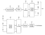
- FIG. 1 illustrates a structural diagram of a communication device for transmission/reception. More specifically in FIG. 1 , the transmitting end includes a channel encoder 101 , a mapper 102 , a serial/parallel (S/P) converter 103 , a multiple antenna encoder 104 , and multiple transmit antennas 105 .
- S/P serial/parallel
- the channel encoder 101 reduces noise effect by adding repeated bits (e.g., cyclic redundancy bits) to the data bits.
- the mapper 102 performs constellation mapping where the data bits are allocated/mapped into data symbols.
- the S/P converter 103 converts serially inputted data into parallel data.
- the multiple antenna encoder 104 encodes the data symbols into time-space signals.
- the multiple antennas 105 transmit the time-space encoded signals to a plurality of channels.
- the receiving end includes multiple receiving antennas 106 , a multiple antenna decoder 107 , a parallel/serial (P/S) converter 108 , a demapper 109 , and a channel decoder 110 .
- the multiple receiving antennas 106 receive signals via the plurality of channels.
- the multiple antenna decoder 107 decodes time-space signals encoded by the multiple antenna encoder 104 and converts the decoded signals into data symbols. Further, the P/S converter 108 converts the parallel symbols into serial symbols. The demapper 109 converts the serial data symbols to bits.
- the channel decoder decodes the channel codes processed through channel encoder 101 and then estimates the data.
- the multiple antenna encoder 104 performs space-time coding.
- Table 1 shows space-time codes derived from two or four transmit antennas.
- the space-time codes of Table 1, namely, (1), (2), and (3), are space-time codes related to two (2) transmit antennas whereas (4), (5), and (6) are space-time codes related to four (4) transmit antennas.
- the use of multiple antennas was proposed for the purposes of increasing capacity, throughput, and/or coverage of the wireless communication system.
- the multiple antennas are used to employ schemes such as a spatial division multiplexing (SDM or SM) and a space-time coding (STC).
- SDM spatial division multiplexing
- STC space-time coding
- the SM scheme sends different data to each of the multiple antennas so as to maximize the transmission rate.
- the STC scheme encodes the symbols across the spatial domain (e.g., antennas) and the time domain to attain diversity gain as well as coding gain so as to increase link level capability.
- a generalized form of the combination of SM and STC schemes is a linear dispersion coding (LDC).
- LDC matrix can be used in encoding/decoding operations of the multiple antennas, and at the same time, in representing various techniques of the multiple antennas.
- the multiple antenna encoding technique according to the LDC matrix can be represented by the following equation.
- i th column of the S transmission matrix represents symbols that are transmitted during the i th time period or time slot
- j th row represents symbols that are transmitted by the j th antenna.
- Equation 2 if each of an actual part ( ⁇ q ) and an imaginary part ( ⁇ q ) of S q is spread across the space-time plane by different dispersion matrix, this can be represented by Equation 2.
- Equation 2 A q and B q each denotes a dispersion matrix, having a size of T ⁇ N t , which is respectively multiplied to the actual part and the imaginary part of S q .
- the receiving signals received by the receiving antennas can be expressed as follows. If the receiving signals are multiplied to S q by the same or identical LDC matrix, then it can be expressed according to the following equation.
- Equation 4 An equivalent channel response can be expressed by Equation 4 if the LDC, as shown in Equation 1, is applied.
- Nr denotes a number of receiving antennas
- y Nr denotes a signal value of the Nr th receiving antenna
- n Nr denotes noise from the Nr th receiving antenna
- H denotes the equivalent channel response
- H denotes a channel response matrix having a size of N r ⁇ N t .
- the receiving signal is applied the LDC of Equation 2
- the receiving signal can be expressed as follows.
- Equation 5 R (subscript) denotes the real part of the signal, and I (subscript) denotes the imaginary part of the signal.
- Equation 6 the equivalent channel response can be expressed as shown in Equation 6.
- Equation 6 h R,n denotes the real parts of the channel response vector received via n th receiving antenna, and h ⁇ I,n denotes the imaginary parts of the channel response vector received via n th receiving antenna.
- the multiple antenna decoding is a process by which transmitted signals are decoded using equations such as Equation 3 or Equation 5.
- the multiple antenna decoding is a process of estimating S q or ⁇ q and ⁇ q .
- a multiple input multiple output (MIMO) can be used increase transmission capacity of the wireless communication system.
- a space-time block coding proposed by Alamouti, ( A Simple Transmit Diversity Technique for Wireless Communications , IEEE JSAC, vol. 16, no. 8, October 1998) is an exemplary transmit diversity technique which uses a plurality of transmitting/receiving antennas to overcome fading in wireless channels.
- the Alamouti proposed scheme uses two (2) transmit antennas, and the diversity order equals a product of a number of transmit antennas and a number of receiving antennas.
- the Alamouti proposed scheme transmits two (2) data symbols during two (2) time slots via two (2) transmit antennas, and as a result, a transmit rate (spatial multiplexing rate) is only 1. Consequently, the spatial multiplexing gain cannot be attained regardless how many receiving antennas are available.
- the Alamouti proposed scheme does not discuss the transmit techniques associated with three (3) or more transmit antennas.
- V-BLAST vertical bell laboratories layered space-time
- This technique is useful if the number of receiving antennas is equal or greater than the number of transmit antennas since independent data signals, corresponding to the number of transmit antennas, can be simultaneously transmitted attaining a maximum spatial multiplexing gain.
- a possible drawback is that there has to be more receiving antennas than the transmit antennas.
- the channel condition is bad and thus the received signal is unsuccessfully decoded, detecting and decoding subsequent signal is likely to be affected as well affecting the system performance.
- Yao and Wornwell proposed another spatial multiplexing technique called tilted-quadrature amplitude multiplexing (QAM) ( Structured Space - Time Block Codes with Optimal Diversity - Multiplexing Tradeoff and Minimum Delay , Globecom, pp. 1941-1945, 2003).
- QAM tilted-quadrature amplitude multiplexing
- This technique is a full diversity and full rate (FDFR) STC which complements an optimal diversity-multiplexing tradeoff proposed by Zheng and Tse.
- Yao's technique is used in a system having two (2) transmit antennas and two (2) receiving antennas where a short space-time block code has a minimum code length of 2.
- the technique employs QAM constellation rotation to attain spatial multiplexing gain as well as full diversity gain.
- shortcomings with this technique is that coding gain is not fully realized since the rotation is a simple rotation of the signal, and the technique is applied and limited to systems having two (2) transmit and receiving antennas, respectively.
- the present invention is directed to a method of encoding space-time codes in a wireless communication system having multiple antennas that substantially obviates one or more problems due to limitations and disadvantages of the related art.
- An object of the present invention is to provide a method of transmitting space-time coded data in a wireless communication system having a plurality of antennas.
- Another object of the present invention is to provide an apparatus for a transmitting space-time coded data in a wireless communication system having a plurality of antennas.
- a method of transmitting space-time coded data in a wireless communication system having a plurality of antennas includes allocating data symbols combined with complex weights to at least two transmit antennas during at least one specified time slot, and transmitting the data symbols combined with complex weights to a receiving end via the at least two transmit antennas during the at least one specified time slot.
- a method of transmitting space-time coded data in a wireless communication system having a plurality of antennas includes allocating data symbols to at least two transmit antennas during at least one specified time slot, and transmitting the data symbols to a receiving end via the at least two transmit antennas during the at least one specified time slot, wherein the data symbols are combined with complex weights.
- an apparatus for transmitting space-time coded data in a wireless communication system having a plurality of antennas includes a multiple antenna encoder for combining complex weights with data symbols and allocating the data symbols combined with complex weights to at least two transmit antennas during at least one specified time slot, and a plurality of antennas for transmitting the data symbols combined with complex weights to a receiving end via the at least two transmit antennas during the at least one specified time slot.
- FIG. 1 illustrates a structural diagram of a communication device for transmission/reception
- FIG. 2 illustrates an example of an effect of a system having two (2) transmit antennas and one (1) receiving antenna using space-time coding
- FIG. 3 illustrates a performance comparison of a communication system, having two (2) transmit antennas and one (1) receiving antenna, using STC schemes
- FIG. 4 illustrates another performance comparison of a communication system, having two (2) transmit antennas and one (1) receiving antenna, using STC schemes
- FIG. 5 illustrates a performance comparison between conventional STC schemes and the STC scheme according to the second embodiment
- FIG. 6 illustrates subcarriers in an OFDM frequency domain.
- the wireless communication system has two (2) transmit antennas.
- Encoding with space-time code with respect to the first embodiment can transmit data symbols in specified number of time slot units.
- space-time coding is applied in a specified number of time slots or time slot units.
- the number of data symbols transmitted during the specified time slots is determined by the number of transmit antennas available in the system and/or by spatial multiplexing rate according to the space-time coding.
- N t (representing the number of transmit antennas) ⁇ R (spatial multiplexing rate) number of data symbols (or a conjugate complex number of the data symbol) and linearly combining weights or weight values for data symbol transmission.
- the weights or weight values can be linearly combined with the data symbols. These weights or weight values can also be referred to as complex weights. Preferably, the weight values can change (or can be set) according to the transmit antenna(s) to be used for transmitting the data symbols. In addition, it is possible to modify the first embodiment to accommodate four (4) transmit antennas.
- Equation 7 shows a communication system having two (2) transmit antennas and a spatial multiplexing rate of 1.
- the signals represented on the same row(s) are transmitted by the same antenna while the signals represented on the same column(s) are transmitted during the same time slot.
- rows represent antennas and the columns represent time.
- the antenna used for transmitting the signal located on the first row can be referred to as Antenna # 1
- the antenna used for transmitting the signal located on the second row can be referred to as Antenna # 2 .
- C New axb an example of the space-time coding will be indicated as C New axb .
- a denotes the number of transmit antennas
- b denotes the spatial time rate according to the space-time coding.
- Equation 7 the data symbols are transmitted during two (2) time slots or time slot units. That is, space-time coding is performed during two (2) time slots. If performing space-time coding of the first embodiment, that is, space-time coding is performed in a specified number of time slots, the data symbols to be transmitted during the specified number of time slots can be transmitted during each time slot, and weight values can be applied to the data symbols to be transmitted during the specified number of time slots.
- two (2) data symbols are transmitted during two (2) time slots.
- the data symbols s 1 and s 2 can be transmitted during the two (2) time slots. That is, s 1 and s 2 can all be transmitted during each time slot.
- specified weights or weight values (w 1 , w 2 , w 3 , w 4 ) can be applied to each data symbol s 1 and s 2 . The details of the weights/weight values will be described below.
- the first transmit antenna i.e., Antenna # 1
- the first transmit antenna can transmit data symbols s 1 and s 2 during the first time slot, and to each data symbol, the weight values are applied.
- the first transmit antenna i.e., Antenna # 1
- the second transmit antenna i.e., Antenna # 2
- the weight values can vary from one time slot to another time slot as well as from one transmit antenna to another transmit antenna. Further, a total power of the transmit antennas during a same time slot is the same.
- an entire set of data symbols to be transmitted during a specified time slot can be transmitted during a single time slot. Further, weights or weight values are applied to all of the data symbols transmitted during the single time slot. Preferably, a result of linearly combined specified weight vector and the data symbol is transmitted during the single time slot.
- weights or weight values can be expressed as shown in Equation 8.
- w 1 e j ⁇ a 2 ⁇ ( 1 + r 2 )
- ⁇ w 2 r ⁇ ⁇ e j ⁇ b 2 ⁇ ( 1 + r 2 )
- ⁇ w 3 r ⁇ ⁇ e j ⁇ c 2 ⁇ ( 1 + r 2 )
- ⁇ w 4 e j ⁇ d 2 ⁇ ( 1 + r 2 ) [ Equation ⁇ ⁇ 8 ]
- Equation 8 is an equation used to describe the weight values used in Equation 7. As such, the weight values can be constructed in different form and not limited to Equation 8. That is, the weight values of Equation 7 can be complex number(s) having different values, and not limited to Equation 8.
- each of the weight values applied in Equation 7 have the same amplitude, and the sum of the phase of any two (2) weight values is same as the sum of the phase of the remaining two (2) weight values. If Equation 9 is satisfied, then a minimum product distance (indicated as ‘dp.min’ in Table 1) with respect to Equation 7 can be optimized.
- Equation 10 is an example of space-time coding according to the first embodiment which satisfies the conditions of Equation 9.
- FIG. 2 illustrates an example of an effect of a system having two (2) transmit antennas and one (1) receiving antenna using space-time coding.
- the space-time coding (STC) scheme of Equation 7 and Alamouti coding scheme (space-time coding scheme (1) of Table 1) are compared. If the data symbols are uncoded (e.g., channel encoding is not applied or turbo-coded, the STC scheme of Equation 7 shows the same optimal result as that of the Alamouti scheme.
- the Alamouti coding as described above with respect to Table 1, provides only one coding method. However, the STC scheme of Equation 7 can use different values for each parameter of Equation 8. That is, each parameter of Equation 8 can have different values to provide various types of space-time coding according to the features/capabilities of different communication systems. As such, the STC scheme of can have better performance than the Alamouti coding scheme in certain communication environments.
- the multiple data symbols are transmitted using two or more transmit antennas.
- each data symbol can be modulated and encoded according to a modulation and coding set (MCS) level, for example.
- MCS modulation and coding set
- the MCS level can be fed back from the receiving end or alternatively, can be determined at the transmitting end.
- each data symbol space-time coded according to Equation 7 can achieve maximum diversity gain.
- the STC of Equation 7 provides equal or similar amount of diversity to each data symbol.
- the data symbols are allocated the same MCS level.
- each data symbol transmitted according to the STC of Equation 7 are applied the same modulation method (e.g., all data symbols mapped using 16 QAM) and the same coding method (e.g., channel coding using the same coding rate).
- the first embodiment is applied to the two (2) antenna system with the spatial multiplexing rate of 2.
- the antenna used to transmit the signal located in the first row is referred to as Antenna # 1 .
- the antenna used to transmit the signal in the second row is referred to as Antenna # 2 .
- the data symbols are transmitted in two (2) time slots.
- the data symbols are space-time coded during the two (2) time slots. If the data symbols are space-time coded during a specified number of time slots according to the first embodiment, all of the data symbols to be transmitted during the specified number of time slots can be transmitted during each time slot, and weight values can be applied to these data symbols.
- Equation 11 four (4) data symbols are transmitted during two (2) time slots. More specifically, the data symbols, s 1 , s 2 , s 3 , s 4 , are transmitted during two (2) time slots, and during each time slot, all of the data symbols, s 1 , s 2 , s 3 , s 4 , are transmitted. Further, weight values, w 1 , w 2 , w 3 , w 4 , w 5 , w 6 , w 7 , w 8 , are applied to the data symbols, s 1 , s 2 , s 3 , s 4 .
- the data symbols, s 1 , s 2 , s 3 , s 4 are transmitted with weight values applied thereto from Antenna # 1 .
- the data symbols, s 1 , s 2 , s 3 , s 4 with weight values applied thereto are transmitted via Antenna # 2 during the first time slot.
- the data symbols, s 1 , s 2 , s 3 , s 4 are transmitted with weight values applied thereto from each of Antenna # 1 and Antenna # 2 .
- the weight values can change or vary based on the time slot and/or each transmit antenna.
- the STC scheme transmits all of the data symbols, which are scheduled to be transmitted during a specified number of time slots, during each time slot. Moreover, weight values are applied to all of the data symbols transmitted during each time slot. Preferably, the result of linearly combined specified weight vector and the data symbol is transmitted during the single time slot.
- Equation 12 shows the weight values related to Equation 11.
- w 1 e j ⁇ ⁇ ⁇ a 4 ⁇ ( 1 + r 2 )
- w 2 r ⁇ ⁇ e j ⁇ ⁇ ⁇ b 4 ⁇ ( 1 + r 2 )
- ⁇ w 3 e j ⁇ ⁇ ⁇ c 4 ⁇ ( 1 + r 2 )
- w 4 r ⁇ ⁇ e j ⁇ ⁇ ⁇ d 4 ⁇ ( 1 + r 2 )
- ⁇ w 5 r ⁇ ⁇ e j ⁇ ⁇ ⁇ e 4 ⁇ ( 1 + r 2 )
- w 6 e j ⁇ ⁇ ⁇ f 4 ⁇ ( 1 + r 2 )
- ⁇ w 7 r ⁇ ⁇ e j ⁇ ⁇ ⁇ g 4 ⁇ ( 1 + r 2 )
- w 8 e j ⁇ ⁇ ⁇ h 4 ⁇ ( 1 +
- Equation 12 is an equation used to describe the weight values used in Equation 11.
- the weight values can be constructed in different form and not limited to Equation 12. That is, the weight values of Equation 11 can be complex number(s) having different values, and not limited to Equation 12.
- w 1 , w 2 , w 3 , w 4 , w 7 , w 8 are pure real numbers
- w 5 , w 6 are pure imaginary numbers
- r can be
- each data symbol space-time coded according to Equation 11 can achieve maximum diversity gain.
- the STC of Equation 11 provides equal or similar amount of diversity to each data symbol.
- the data symbols are allocated the same MCS level.
- each data symbol transmitted according to the STC of Equation 11 are applied the same modulation method (e.g., all data symbols mapped using 16 QAM) and the same coding method (e.g., channel coding using the same coding rate).
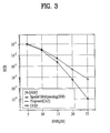
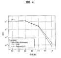
- FIG. 3 and FIG. 4 illustrate a performance comparison of a communication system, having two (2) transmit antennas and one (1) receiving antenna, using STC schemes.
- the graph of FIG. 3 shows the performance of the 4-QAM constellation mapping scheme without STC.
- the graph of FIG. 4 shows the performance of the 4-QAM constellation mapping scheme with turbo-coding.
- FIG. 3 is a result of comparing the spatial multiplexing (SM) scheme (2) of Table 1, a generalized optimal diversity (GOD) scheme (3) of Table 1, and space-time coding (STC) scheme of Equation 11.
- the STC scheme of Equation 11 uses two (2) transmit antennas with the SM rate of 2.
- the STC scheme (2) of Table 1 and the GOD scheme (3) of Table 1 are used to show the performance of Equation 11.
- the STC of Equation 11 shows better performance than the SM coding while showing similar to equal performance to the GOD coding.
- FIG. 4 illustrates a comparison of the GOD scheme between scheme (3) of Table 1 and STD scheme of Equation 11. As shown in FIG. 3 , the two schemes showed same performance result even when no channel coding was used. However, when turbo coding was used for channel coding, the STC scheme of Equation 11 showed better performance. Further, turbo code for space-time coding according to Equation 11 showed better performance than the GOD coding scheme as well.
- the STC according to the first embodiment showed equal performance in certain situations.
- the STC according to the first embodiment is able to manipulate the weight values applied to the data symbols.
- different characteristics can be expressed based on the channel condition even if the STC is the same.
- the STC according to the embodiment of the present invention can have better performance than the conventional STC in certain situations.
- the space-time coding can be applied in a communication system having four (4) transmit antennas.
- the STC scheme can be represented by the data symbols being transmitted during a specified number of time slots.
- weight values are applied to each data symbol (or to the conjugate complex number of the data symbol) before being transmitted to the receiving end.
- the weight values applied to the data symbols are preferably changed or modified based on the antenna which is used to transmit the data symbols.
- the weight values are preferably changed or modified based on the time slots which are used to transmit the weight-applied data symbol.
- the discussion of the second embodiment is based on the wireless communication system having four (4) antennas which is an expanded modification from the first embodiment.
- Equation 14 shows the STC scheme of a communication system having four (4) antennas and the spatial multiplexing rate of 1.
- the signals located on the same row(s) are transmitted by the same antenna while the signals located on the same column(s) are transmitted during the same time slot.
- rows represent antennas and the columns represent time.
- the antenna used for transmitting the signal located on the first row can be referred to as Antenna # 1
- the antenna used for transmitting the signal located on the second row can be referred to as Antenna # 2
- the antenna used for transmitting the signal located on the third row can be referred to as Antenna # 3
- the antenna used for transmitting the signal located on the fourth row can be referred to as Antenna # 4 .
- the data symbols are transmitted during four (4) time slots.
- each transmit antenna transmits a specific data symbol
- all of the data symbols to be transmitted via the specified antennas are transmitted during the specified number of time slots
- weight values are applied to the data symbols transmitted during the specified number of time slots.
- each transmit antenna transmits four (4) data symbols, s 1 , s 2 , s 3 , s 4 , during four (4) time slots. Further, each transmit antenna transmits two (2) data symbols during four (4) time slots. The data symbols, s 1 and s 2 , are transmitted via Antenna # 1 and Antenna # 2 , respectively, during the first two (2) time slots of the four (4) time slots. Moreover, the weight values, w 1 , w 2 , w 3 , w 4 , are applied to each data symbol, s 1 and s 2 .
- the data symbols, s 3 and s 4 are transmitted via Antenna # 3 and Antenna 4 , respectively, during the third and four time slots.
- the weight values, w 1 , w 2 , w 3 , w 4 are applied to each data symbol, s 3 and s 4 .
- the weight values applied to data symbols can vary/change from one time slot to another, and also from one antenna to another.
- Equation 14 The weights or weight values as shown in Equation 14 can be expressed according to Equation 15.
- w 1 e j ⁇ ⁇ ⁇ a 2 ⁇ ( 1 + r 2 )
- ⁇ w 2 r ⁇ ⁇ e j ⁇ ⁇ ⁇ b 2 ⁇ ( 1 + r 2 )
- ⁇ w 3 r ⁇ ⁇ e j ⁇ ⁇ ⁇ c 2 ⁇ ( 1 + r 2 )
- ⁇ w 4 e j ⁇ ⁇ ⁇ d 2 ⁇ ( 1 + r 2 ) , [ Equation ⁇ ⁇ 15 ]
- Equation 15 is an equation used to describe the weight values used in Equation 14. As such, the weight values can be constructed in different form and not limited to Equation 14. That is, the weight values of Equation 15 can be complex number(s) having different values, and not limited to Equation 15.
- each of the weight values applied in Equation 14 have the same amplitude, and the sum of the phase of any two (2) weight values is same as the sum of the phase of the remaining two (2) weight values. If Equation 16 is satisfied, then a minimum product distance (indicated as ‘dp.min’ in Table 1) with respect to Equation 7 can be optimized.
- the STC scheme of Equation 14 corresponds to the STC scheme indicated by (5) of Table 1.
- the STC scheme of Equation 14 shows similar to equal effectiveness to that of scheme (5) of Table 1.
- the STC scheme of Equation 14 can be used to manipulate the weight values to provide various STC combinations for further effectiveness.
- the data symbols, s 1 and s 2 are transmitted after being combined.
- the data symbols, s 1 and s 2 transmitted via Antenna # 2 are also combined before transmission.
- the data symbols, s 3 and s 4 are combined and transmitted via Antenna # 3 and Antenna # 4 , respectively.
- the data symbols, s 1 and s 2 are transmitted via the same channel (i.e., first channel) while the data symbols, s 3 and s 4 , are transmitted via the same channel (i.e., second channel).
- the same MCS level can be applied to the data symbols transmitted during the same specified time slot. That is, a first MCS level is assigned to the data symbols, s 1 and s 2 , and a second MCS level is assigned to the data symbols, s 3 and s 4 .
- the first MCS level and the second MCS level can be same or different.
- the space-time coding which does not provide full diversity, is used, it is preferable to assign the same level MCS level to the weight-combined data symbols which are transmitted during a specific time slot.
- the following is another example of space-time coding in a four (4) antenna system in which the space multiplexing rate is 1.
- Equation 17 the data symbols are transmitted during four (4) time slots. That is, the space-time coding is performed during four (4) time slots.
- the superscript R represents a real number of a complex number
- I represents an imaginary number of a complex number.
- all four (4) antennas transmit signals ⁇ tilde over (x) ⁇ 1 , ⁇ tilde over (x) ⁇ 2 , ⁇ tilde over (x) ⁇ 3 , ⁇ tilde over (x) ⁇ 4 which correspond to data symbols s 1 , s 2 , s 3 , s 4 during four (4) time slots.
- each transmit antenna transmits signals which correspond to data symbols s 1 , s 2 , s 3 , s 4 during the four (4) time slots.
- ⁇ tilde over (x) ⁇ 1 and ⁇ tilde over (x) ⁇ 2 corresponding to the data symbols s 1 , s 2 , s 3 , s 4 are transmitted via Antenna # 1 and Antenna # 2 , respectively, the signals are transmitted during the first two time slots out of four (4) time slots, and specific weight values w 1 , w 2 , w 3 , w 4 are applied.
- ⁇ tilde over (x) ⁇ 3 and ⁇ tilde over (x) ⁇ 4 corresponding to the data symbols s 1 , s 2 , s 3 , s 4 are transmitted via Antenna # 3 and Antenna # 4 , respectively, the signals are transmitted during the last two time slots out of four (4) time slots, and specific weight values w 1 , w 2 , w 3 , w 4 are applied.
- Antenna # 1 and Antenna # 2 can be used to transmit ⁇ tilde over (x) ⁇ 1 and ⁇ tilde over (x) ⁇ 2 corresponding to the data symbols s 1 , s 2 , s 3 , s 4 , respectively
- Antenna # 3 and Antenna # 4 can be used to transmit ⁇ tilde over (x) ⁇ 3 and ⁇ tilde over (x) ⁇ 4 corresponding to the data symbols s 1 , s 2 , s 3 , s 4 , respectively.
- the weight values applied to the signals, ⁇ tilde over (x) ⁇ 1 , ⁇ tilde over (x) ⁇ 2 , ⁇ tilde over (x) ⁇ 3 , ⁇ tilde over (x) ⁇ 4 , or the weight values applied to the data symbols, s 1 , s 2 , s 3 , s 4 , can vary from one time slot to another and can also vary from one transmit antenna to another.
- weights or weight values can be expressed as shown in Equation 18.
- w 1 e j ⁇ ⁇ ⁇ a 2 ⁇ ( 1 + r 2 )
- ⁇ w 2 r ⁇ ⁇ e j ⁇ ⁇ ⁇ b 2 ⁇ ( 1 + r 2 )
- ⁇ w 3 r ⁇ ⁇ e j ⁇ ⁇ ⁇ c 2 ⁇ ( 1 + r 2 )
- ⁇ w 4 e j ⁇ ⁇ ⁇ d 2 ⁇ ( 1 + r 2 ) , [ Equation ⁇ ⁇ 18 ]
- Equation 18 is an equation used to describe the weight values used in Equation 17. As such, the weight values can be constructed in different form and not limited to Equation 18. That is, the weight values of Equation 17 can be complex number(s) having different values, and not limited to Equation 18.
- the weight values (w 1 , w 2 , w 3 , w 4 ) can be determined using phase values ( ⁇ a , ⁇ b , ⁇ c , ⁇ d ) and a real number r. These variable numbers can be of different values. In other words, the variable numbers can have a different optimal value based on the system, and if the transmitting/receiving end lacks the channel information, the variable number can have optimum capability by satisfying Equation 19 and Equation 20.
- each of the weight values applied in Equation 18 have the same amplitude, and the sum of the phase of any two (2) weight values is same as the sum of the phase of the remaining two (2) weight values.
- ⁇ r can be used to determine x i and s i .
- the STC of Equation 17 can be used to improve the STC of Equation 14.
- the STC of Equation 17 has a rank of 4, and a minimum product distance of 0.25.
- the rank corresponds to diversity gain based on space-time coding, and the minimum product distance corresponds to coding gain.
- a same MCS level is preferably assigned to the data symbols transmitted according to the STC scheme of Equation 17.
- the same MCS level is applied to each data symbol transmitted according to the STC scheme of Equation 17.
- the following is another example of space-time coding that can be applied to a four (4) antenna system in which the spatial multiplexing rate is 1.
- Equation 21 the data symbols are transmitted during four (4) time slots. That is, the space-time coding is performed during four (4) time slots.
- Equation 21 four (4) data symbols are transmitted via four (4) antennas during four (4) time slots.
- each transmit antenna transmits four (4) data symbols during four (4) time slots. If data symbols, s 1 , s 2 , s 3 , s 4 , are transmitted via Antenna # 1 and Antenna # 2 , these data symbols are transmitted during the first two (2) out of four (4) time slots, and the weight values, w 1 , w 2 , w 3 , w 4 , are applied to each data symbol.
- the each antenna according to the second embodiment can be used to transmit specific data symbol.
- all transmit antennas can be used to transmit the data symbols, s 1 , s 2 , s 3 , s 4 .
- the weight values applied to the data symbols, s 1 , s 2 , s 3 , s 4 can vary from one time slot to another as well as from one antenna to another.
- Equation 22 shows the weight values related to Equation 21.
- w 1 e j ⁇ ⁇ ⁇ a 4 ⁇ ( 1 + r 2 )
- ⁇ w 2 r ⁇ ⁇ e j ⁇ ⁇ ⁇ b 4 ⁇ ( 1 + r 2 )
- ⁇ w 3 ⁇ e j ⁇ ⁇ ⁇ c 4 ⁇ ( 1 + r 2 )
- ⁇ w 4 r ⁇ ⁇ e j ⁇ ⁇ d 4 ⁇ ( 1 + r 2 )
- ⁇ w 5 r ⁇ ⁇ e j ⁇ ⁇ ⁇ e 4 ⁇ ( 1 + r 2 )
- ⁇ w 6 ⁇ e j ⁇ ⁇ ⁇ f 4 ⁇ ( 1 + r 2 )
- ⁇ w 7 r ⁇ ⁇ e j ⁇ ⁇ ⁇ g 4 ⁇ ( 1 + r 2 )
- ⁇ w 8 ⁇ e j
- Equation 22 is an equation used to describe the weight values used in Equation 21.
- the weight values can be constructed in different form and not limited to Equation 22. That is, the weight values of Equation 21 can be complex number(s) having different values, and not limited to Equation 22.
- w 1 , w 2 , w 3 , w 4 , w 7 , w 8 are determined by phase values, ⁇ a , ⁇ b , ⁇ c , ⁇ d , ⁇ e , ⁇ f , ⁇ g , ⁇ h , and a real number, r.
- these variable numbers can be of different values.
- the variable numbers can have a different optimal value based on the system, and if the transmitting/receiving end lacks the channel information, the variable number can have optimum capability by satisfying Equation 23.
- w 1 , w 2 , w 3 , w 4 , w 7 , w 8 are real numbers
- w 5 , w 6 are imaginary numbers
- r can be
- the data symbols, which are transmitted according to the STC of Equation 21 are allocated the same MCS level.
- each data symbol transmitted according to the STC of Equation 21 are applied the same modulation method and the same coding method.
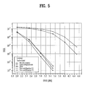
- FIG. 5 illustrates a performance comparison between conventional STC schemes and the STC scheme according to the second embodiment.
- the result of FIG. 5 is based on using turbo coding for space-time coding, and if 4-QAM is used, a generalized optimal diversity (GOD) scheme (3) of Table 1, a quasi-orthogonal code STC scheme (4) of Table 1, A-matrix, proposed in IEEE 802.16e, STC scheme (5) of Table 1, a result of Equation 17, and a result of Equation 21.
- GOD generalized optimal diversity
- Equation 17 is an improvement from the conventional optimum STC scheme.
- the following is an example of space-time coding that can be applied to a four (4) antennas system.
- Equation 24 the data symbols are transmitted during two (2) time slots. That is, space-time coding is performed during two (2) time slots.
- these four (4) antennas are used to transmit four (4) data symbols, s 1 , s 2 , s 3 , s 4 , during two (2) time slots.
- each antenna transmits two (2) data symbols during two (2) time slots.
- the data symbols, s 1 and s 2 are transmitted via Antenna # 1 and Antenna # 2 , respectively.
- the weight values, w 1 , w 2 , w 3 , w 4 are applied to each data symbol, s 1 and s 2 .
- the data symbols, s 3 and s 4 are transmitted via Antenna # 3 and Antenna 4 , respectively.
- the weight values, w 1 , w 2 , w 3 , w 4 are applied to each data symbol, s 3 and s 4 .
- the weight values applied to data symbols can vary/change from one time slot to another, and also from one antenna to another.
- Equation 24 The weights or weight values as shown in Equation 24 can be expressed according to Equation 25.
- w 1 e j ⁇ ⁇ ⁇ a 2 ⁇ ( 1 + r 2 )
- ⁇ w 2 r ⁇ ⁇ e j ⁇ ⁇ ⁇ b 2 ⁇ ( 1 + r 2 )
- ⁇ w 3 r ⁇ ⁇ e j ⁇ ⁇ ⁇ c 2 ⁇ ( 1 + r 2 )
- ⁇ w 4 e j ⁇ ⁇ ⁇ d 2 ⁇ ( 1 + r 2 ) , [ Equation ⁇ ⁇ 25 ]
- Equation 25 is an equation used to describe the weight values used in Equation 24. As such, the weight values can be constructed in different form and not limited to Equation 24. That is, the weight values of Equation 25 can be complex number(s) having different values, and not limited to Equation 25.
- each of the weight values applied in Equation 24 have the same amplitude, and the sum of the phase of any two (2) weight values is same as the sum of the phase of the remaining two (2) weight values. If Equation 26 is satisfied, then a minimum product distance (indicated as ‘dp.min’ in Table 1) with respect to Equation 24 can be optimized.
- the STC scheme of Equation 24 does not provide full diversity. Further, it is preferable that a same modulation level and a same coding level is applied to the data symbols, which are linearly combined with specific weight values during a specified time slot. For example, the data symbols, s 1 and s 2 , are assigned a first MCS level while the data symbols, s 3 and s 4 , are assigned a second MCS level.
- the following is another example of space-time coding that can be applied to a four (4) antennas system.
- Equation 27 the data symbols are transmitted during two (2) time slots. That is, the space-time coding is performed during two (2) time slots.
- ⁇ tilde over (x) ⁇ 2 x 2 R +jx 4 I
- ⁇ tilde over (x) ⁇ 3 x 3 R +jx 1 I
- ⁇ tilde over (x) ⁇ 4 x 4 R +jx 2 I .
- the superscript R represents a real number of a complex number
- I represents an imaginary number of a complex number.
- all four (4) antennas transmit signals ⁇ tilde over (x) ⁇ 1 , ⁇ tilde over (x) ⁇ 2 , ⁇ tilde over (x) ⁇ 3 , ⁇ tilde over (x) ⁇ 4 which correspond to data symbols s 1 , s 2 , s 3 , s 4 during four (4) time slots.
- each transmit antenna transmits signals which correspond to data symbols s 1 , s 2 , s 3 , s 4 during the four (4) time slots.
- ⁇ tilde over (x) ⁇ 1 and ⁇ tilde over (x) ⁇ 2 corresponding to the data symbols s 1 , s 2 , s 3 , s 4 are transmitted via Antenna # 1 and Antenna # 2 , respectively, the signals are transmitted during the first two time slots out of four (4) time slots, and specific weight values w 1 , w 2 , w 3 , w 4 are applied.
- ⁇ tilde over (x) ⁇ 3 and ⁇ tilde over (x) ⁇ 4 corresponding to the data symbols s 1 , s 2 , s 3 , s 4 are transmitted via Antenna # 3 and Antenna # 4 , respectively, the signals are transmitted during the last two time slots out of four (4) time slots, and specific weight values w 1 , w 2 , w 3 , w 4 are applied.
- Antenna # 1 and Antenna # 2 can be used to transmit ⁇ tilde over (x) ⁇ 1 and ⁇ tilde over (x) ⁇ 2 corresponding to the data symbols s 1 , s 2 , s 3 , s 4 , respectively
- Antenna # 3 and Antenna # 4 can be used to transmit ⁇ tilde over (x) ⁇ 1 and ⁇ tilde over (x) ⁇ 2 corresponding to the data symbols s 1 , s 2 , s 3 , s 4 , respectively.
- the weight values applied to the signals, ⁇ tilde over (x) ⁇ 1 , ⁇ tilde over (x) ⁇ 2 , ⁇ tilde over (x) ⁇ 3 , ⁇ tilde over (x) ⁇ 4 , or the weight values applied to the data symbols, s 1 , s 2 , s 3 , s 4 , can vary from one time slot to another and can also vary from one transmit antenna to another.
- weights or weight values can be expressed as shown in Equation 28.
- w 1 e j ⁇ ⁇ ⁇ a 2 ⁇ ( 1 + r 2 )
- w 2 r ⁇ ⁇ e j ⁇ ⁇ ⁇ b 2 ⁇ ( 1 + r 2 )
- ⁇ w 3 r ⁇ ⁇ e j ⁇ ⁇ ⁇ c 2 ⁇ ( 1 + r 2 )
- w 4 ⁇ e j ⁇ ⁇ ⁇ d 2 ⁇ ( 1 + r 2 ) [ Equation ⁇ ⁇ 28 ]
- Equation 28 is an equation used to describe the weight values used in Equation 27.
- the weight values can be constructed in different form and not limited to Equation 28. That is, the weight values of Equation 27 can be complex number(s) having different values, and not limited to Equation 28.
- the weight values (w 1 , w 2 , w 3 , w 4 ) can be determined using phase values, ⁇ a , ⁇ b , ⁇ c , ⁇ d , and a real number r. These variable numbers can be of different values. In other words, the variable numbers can have a different optimal value based on the system, and if the transmitting/receiving end lacks the channel information, the variable number can have optimum capability by satisfying Equation 29 and Equation 30.
- each of the weight values applied in Equation 28 have the same amplitude, and the sum of the phase of any two (2) weight values is same as the sum of the phase of the remaining two (2) weight values.
- ⁇ r can be used to determine x i and s i .
- the STC of Equation 27 does not provide full diversity.
- ⁇ tilde over (x) ⁇ 1 and ⁇ tilde over (x) ⁇ 2 corresponding to the data symbols s 1 , s 2 , s 3 , s 4 are transmitted via Antenna # 1 and Antenna # 2 , respectively, the signals are transmitted.
- ⁇ tilde over (x) ⁇ 3 and ⁇ tilde over (x) ⁇ 4 corresponding to the data symbols s 1 , s 2 , s 3 , s 4 are transmitted via Antenna # 3 and Antenna # 4 , respectively.
- all of the data symbols, s 1 , s 2 , s 3 , s 4 are combined during a specified time slot and then transmitted.
- a same MCS level is assigned to all of the data symbols.
- the superscript R represents a real number of a complex number
- I represents an imaginary number of a complex number.
- Equation 31 a total of four (4) antennas transmit signals ⁇ tilde over (x) ⁇ 1 , ⁇ tilde over (x) ⁇ 2 , ⁇ tilde over (x) ⁇ 3 , ⁇ tilde over (x) ⁇ 4 , ⁇ tilde over (x) ⁇ 5 , ⁇ tilde over (x) ⁇ 6 , ⁇ tilde over (x) ⁇ 7 , ⁇ tilde over (x) ⁇ 8 which correspond to data symbols s 1 , s 2 , s 3 , s 4 , s 5 , s 6 , s 7 , s 8 during four (4) time slots.
- each transmit antenna transmits signals which correspond to data symbols s 1 , s 2 , s 3 , s 4 , s 5 , s 6 , s 7 , s 8 during the four (4) time slots.
- ⁇ tilde over (x) ⁇ 1 , ⁇ tilde over (x) ⁇ 2 , ⁇ tilde over (x) ⁇ 3 , ⁇ tilde over (x) ⁇ 4 corresponding to the data symbols s 1 , s 2 , s 3 , s 4 , s 5 , s 6 , s 7 , s 8 are transmitted via Antenna # 1 and Antenna # 2 , respectively, the signals are transmitted during the first two time slots out of four (4) time slots, and specific weight values w 1 , w 2 , w 3 , w 4 , w 5 , w 6 , w 7 , w 8 are applied.
- ⁇ tilde over (x) ⁇ 5 , ⁇ tilde over (x) ⁇ 6 , ⁇ tilde over (x) ⁇ 7 , ⁇ tilde over (x) ⁇ 8 corresponding to the data symbols s 1 , s 2 , s 3 , s 4 , s 5 , s 6 , s 7 , s 8 are transmitted via Antenna # 3 and Antenna # 4 , respectively, the signals are transmitted during the last two time slots out of four (4) time slots, and specific weight values w 1 , w 2 , w 3 , w 4 , w 5 , w 6 , w 7 , w 8 are applied.
- Antenna # 1 and Antenna # 2 can be used to transmit ⁇ tilde over (x) ⁇ 1 , ⁇ tilde over (x) ⁇ 2 , ⁇ tilde over (x) ⁇ 3 , ⁇ tilde over (x) ⁇ 4 corresponding to the data symbols s 1 , s 2 , s 3 , s 4 , s 5 , s 6 , s 7 , s 8 , respectively, and Antenna # 3 and Antenna # 4 can be used to transmit ⁇ tilde over (x) ⁇ 5 , ⁇ tilde over (x) ⁇ 6 , ⁇ tilde over (x) ⁇ 7 , ⁇ tilde over (x) ⁇ 8 corresponding to the data symbols s 1 , s 2 , s 3 , s 4 , s 5 , s 6 , s 7 , s 8 , respectively.
- the weight values applied to the signals, ⁇ tilde over (x) ⁇ 1 , ⁇ tilde over (x) ⁇ 2 , ⁇ tilde over (x) ⁇ 3 , ⁇ tilde over (x) ⁇ 4 , or the weight values applied to the data symbols, s 1 , s 2 , s 3 , s 4 , can vary from one time slot to another and can also vary from one transmit antenna to another.
- Equation 32 shows the weight values related to Equation 21.
- w 1 e j ⁇ ⁇ ⁇ a 4 ⁇ ( 1 + r 2 )
- w 2 r ⁇ ⁇ e j ⁇ ⁇ ⁇ b 4 ⁇ ( 1 + r 2 )
- ⁇ w 3 e j ⁇ ⁇ ⁇ c 4 ⁇ ( 1 + r 2 )
- w 4 r ⁇ ⁇ e j ⁇ ⁇ ⁇ d 4 ⁇ ( 1 + r 2 )
- ⁇ w 5 r ⁇ ⁇ e j ⁇ ⁇ ⁇ e 4 ⁇ ( 1 + r 2 )
- w 6 e j ⁇ ⁇ ⁇ f 4 ⁇ ( 1 + r 2 )
- ⁇ w 7 r ⁇ ⁇ e j ⁇ ⁇ ⁇ g 4 ⁇ ( 1 + r 2 )
- w 8 e j ⁇ ⁇ ⁇ h 4 ⁇ ( 1 +
- Equation 32 is an equation used to describe the weight values used in Equation 31.
- the weight values can be constructed in different form and not limited to Equation 32. That is, the weight values of Equation 31 can be complex number(s) having different values, and not limited to Equation 32.
- w 1 , w 2 , w 3 , w 4 , w 7 , w 8 are determined by phase values, ⁇ a , ⁇ b , ⁇ c , ⁇ d , ⁇ e , ⁇ f , ⁇ g , ⁇ h , and a real number, r.
- these variable numbers can be of different values.
- the variable numbers can have a different optimal value based on the system, and if the transmitting/receiving end lacks the channel information, the variable number can have optimum capability by satisfying Equation 33.
- w 1 , w 2 , w 3 , w 4 , w 7 , w 8 are real numbers
- w 5 , w 6 are imaginary numbers
- r can be
- ⁇ r can be used to determine x i and s i , preferably.
- the STC of Equation 27 does not provide full diversity. However, ⁇ tilde over (x) ⁇ 1 , ⁇ tilde over (x) ⁇ 2 , ⁇ tilde over (x) ⁇ 3 , ⁇ tilde over (x) ⁇ 4 corresponding to the data symbols s 1 , s 2 , s 3 , s 4 , s 5 , s 6 , s 7 , s 8 are transmitted via Antenna # 1 and Antenna # 2 , respectively, the signals are transmitted.
- ⁇ tilde over (x) ⁇ 5 , ⁇ tilde over (x) ⁇ 6 , ⁇ tilde over (x) ⁇ 7 , ⁇ tilde over (x) ⁇ 8 corresponding to the data symbols s 1 , s 2 , s 3 , s 4 , s 5 , s 6 , s 7 , s 8 are transmitted via Antenna # 3 and Antenna # 4 , respectively.
- all of the data symbols, s 1 , s 2 , s 3 , s 4 , s 5 , s 6 , s 7 , s 8 are combined during a specified time slot and then transmitted.
- a same MCS level is uniformly assigned to all of the data symbols.
- the STC scheme according to the embodiment of the present invention can be further explained with space-time coded matrix C. That is, space-time coding can be performed using the STC schemes of Equations 7, 11, 14, 17, 21, 24, 27, and 31.
- the aforementioned equations are examples of the STC schemes, and the STC matrix of these equations can be modified into a new or different STC matrix by a unitary matrix. That is, a unitary matrix can be multiplied to the STC matrix to form a different or a new STC matrix.
- Equation 35 A unitary matrix, U, can be shown according to Equation 35.
- the determinant of the original STC matrix is unaffected or unchanged. As such, the performance of the original STC matrix is unchanged.
- Equation 37 An example of modified STC matrix by multiplying the unitary matrix can be shown in Equation 37.
- the unitary matrix is multiplied to the STC matrix of Equation 10.
- Equation 38 a unitary matrix can be multiplied to a specified STC matrix to make a modified matrix as shown as an example in Equation 38.
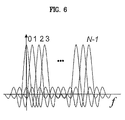
- the weight values (also referred to as complex weights) of the space-time codes can be applied to an orthogonal frequency division multiplexing (OFDM) system. If the weight values of the STC are applied to the OFDM system, then different weight values can be applied based on frequency carrier index.
- FIG. 6 illustrates subcarriers in an OFDM frequency domain. Here, the system can be represented by N ⁇ 1 number of subcarriers.
Landscapes
- Engineering & Computer Science (AREA)
- Computer Networks & Wireless Communication (AREA)
- Signal Processing (AREA)
- Radio Transmission System (AREA)
- Mobile Radio Communication Systems (AREA)
Abstract
Description
| TABLE 1 | ||||
| Number | dp.min (minimum | |||
| of | Rank | product distance) | ||
| Scheme | Rate | Antennas | (Tx) | (QPSK) |
| (1) |
|
1 | 2 | 1 | 1 |
| (2) |
|
2 | 2 | 1 | 1 |
| (3) |
|
2 | 2 | 2 | 0.2 |
| (4) |
|
1 | 4 | 2 | 4 |
| (5) |
|
1 | 4 | 2 | 1 |
| (6) |
|
2 | 4 | 2 | 1 |
H=I r {circle around (x)}H, χ=[vec(M 0)vec(M 1) . . . vec(M Q)] [Equation 4]
θa+θb=θc+θd , r=1 [Equation 9]
θa+θb=θc+θd , r=1 [Equation 16]
θa+θb=θc+θd , r=1 [Equation 19]
θa+θb=θc+θd , r=1 [Equation 26]
θa+θb=θc+θd , r=1 [Equation 29]
U×U H =I, det(U)=1 [Equation 35]
det(C×U)=det(C)det(U)=det(C) [Equation 36]
Claims (20)
Priority Applications (1)
| Application Number | Priority Date | Filing Date | Title |
|---|---|---|---|
| US12/091,719 US8144795B2 (en) | 2005-10-26 | 2006-10-26 | Method for encoding space-time codes in a wireless communication system having multiple antennas |
Applications Claiming Priority (7)
| Application Number | Priority Date | Filing Date | Title |
|---|---|---|---|
| US73062905P | 2005-10-26 | 2005-10-26 | |
| US73608605P | 2005-11-10 | 2005-11-10 | |
| KR1020060029058A KR101241881B1 (en) | 2005-10-26 | 2006-03-30 | Method for encoding space-time codes in multi-antenna system |
| KR1020060029058 | 2006-03-30 | ||
| KR10-2006-0029058 | 2006-03-30 | ||
| PCT/KR2006/004396 WO2007049926A2 (en) | 2005-10-26 | 2006-10-26 | Method for encoding space-time codes in a wireless communication system having multiple antennas |
| US12/091,719 US8144795B2 (en) | 2005-10-26 | 2006-10-26 | Method for encoding space-time codes in a wireless communication system having multiple antennas |
Publications (2)
| Publication Number | Publication Date |
|---|---|
| US20080317157A1 US20080317157A1 (en) | 2008-12-25 |
| US8144795B2 true US8144795B2 (en) | 2012-03-27 |
Family
ID=38271068
Family Applications (1)
| Application Number | Title | Priority Date | Filing Date |
|---|---|---|---|
| US12/091,719 Expired - Fee Related US8144795B2 (en) | 2005-10-26 | 2006-10-26 | Method for encoding space-time codes in a wireless communication system having multiple antennas |
Country Status (4)
| Country | Link |
|---|---|
| US (1) | US8144795B2 (en) |
| KR (1) | KR101241881B1 (en) |
| TW (1) | TWI465083B (en) |
| WO (1) | WO2007049926A2 (en) |
Cited By (2)
| Publication number | Priority date | Publication date | Assignee | Title |
|---|---|---|---|---|
| US20100277339A1 (en) * | 2007-06-15 | 2010-11-04 | Worcester Polytechnic Institute | Precision location methods and systems |
| US20110101889A1 (en) * | 2008-07-08 | 2011-05-05 | Koninklijke Philips Electronics N.V. | Methods and apparatus for determining relative positions of led lighting units |
Families Citing this family (7)
| Publication number | Priority date | Publication date | Assignee | Title |
|---|---|---|---|---|
| US8107543B2 (en) * | 2006-06-27 | 2012-01-31 | Amimon Ltd. | High diversity time-space coding and decoding for MIMO systems |
| KR100908132B1 (en) | 2007-12-13 | 2009-07-16 | 한국전자통신연구원 | Signal Transmission Method in Satellite Communication System with Terrestrial Aids |
| FR2927205A1 (en) * | 2008-01-31 | 2009-08-07 | Commissariat Energie Atomique | LOW PAPR SPATIO-TEMPORAL ENCODING METHOD FOR IMPULSE UWB TYPE MULTI-ANTENNA COMMUNICATION SYSTEM |
| WO2009120028A2 (en) * | 2008-03-27 | 2009-10-01 | Electronics And Telecommunications Research Institute | Wireless multi-carrier code division multiplexing communication apparatus using transmit diversity scheme |
| US8693890B2 (en) * | 2010-08-20 | 2014-04-08 | Nec Laboratories America, Inc. | Look-up table and digital transmitter based architecture for fiber nonlinearity compensation |
| WO2016144041A1 (en) * | 2015-03-09 | 2016-09-15 | 한국항공우주연구원 | Packet encoding device and method |
| KR101754527B1 (en) | 2015-03-09 | 2017-07-06 | 한국항공우주연구원 | Apparatus and method for coding packet |
Citations (8)
| Publication number | Priority date | Publication date | Assignee | Title |
|---|---|---|---|---|
| WO2001076094A2 (en) | 2000-03-31 | 2001-10-11 | Nokia Mobile Phones Ltd. | Space-time code for multiple antenna transmission |
| WO2002080375A2 (en) | 2001-03-28 | 2002-10-10 | Nokia Corporation | Non-zero complex weighted space-time code for multiple antenna transmission |
| US20040066761A1 (en) | 2002-04-22 | 2004-04-08 | Giannakis Georgios B. | Space-time coding using estimated channel information |
| US20040202256A1 (en) | 2003-03-08 | 2004-10-14 | Giannakis Georgios B. | Space-time coding for multi-antenna ultra-wideband transmissions |
| US20050070323A1 (en) * | 2003-09-30 | 2005-03-31 | Angel Lozano | Method for optimizing the transmit signal in multiple antenna wireless links |
| US20070297529A1 (en) * | 2005-11-17 | 2007-12-27 | Shengli Zhou | Recursive and trellis-based feedback reduction for MIMO-OFDM with rate-limited feedback |
| US7327795B2 (en) * | 2003-03-31 | 2008-02-05 | Vecima Networks Inc. | System and method for wireless communication systems |
| US7403748B1 (en) * | 2000-04-07 | 2008-07-22 | Nokia Coporation | Multi-antenna transmission method and system |
Family Cites Families (2)
| Publication number | Priority date | Publication date | Assignee | Title |
|---|---|---|---|---|
| CN1170374C (en) * | 2002-06-20 | 2004-10-06 | 大唐移动通信设备有限公司 | Space-time compilation code method suitable for frequency selective fading channels |
| KR100541285B1 (en) * | 2002-10-02 | 2006-01-10 | 엘지전자 주식회사 | Signal Processing Method in Multiple Input / Output Communication System |
-
2006
- 2006-03-30 KR KR1020060029058A patent/KR101241881B1/en not_active Expired - Fee Related
- 2006-10-26 TW TW095139569A patent/TWI465083B/en not_active IP Right Cessation
- 2006-10-26 WO PCT/KR2006/004396 patent/WO2007049926A2/en not_active Ceased
- 2006-10-26 US US12/091,719 patent/US8144795B2/en not_active Expired - Fee Related
Patent Citations (8)
| Publication number | Priority date | Publication date | Assignee | Title |
|---|---|---|---|---|
| WO2001076094A2 (en) | 2000-03-31 | 2001-10-11 | Nokia Mobile Phones Ltd. | Space-time code for multiple antenna transmission |
| US7403748B1 (en) * | 2000-04-07 | 2008-07-22 | Nokia Coporation | Multi-antenna transmission method and system |
| WO2002080375A2 (en) | 2001-03-28 | 2002-10-10 | Nokia Corporation | Non-zero complex weighted space-time code for multiple antenna transmission |
| US20040066761A1 (en) | 2002-04-22 | 2004-04-08 | Giannakis Georgios B. | Space-time coding using estimated channel information |
| US20040202256A1 (en) | 2003-03-08 | 2004-10-14 | Giannakis Georgios B. | Space-time coding for multi-antenna ultra-wideband transmissions |
| US7327795B2 (en) * | 2003-03-31 | 2008-02-05 | Vecima Networks Inc. | System and method for wireless communication systems |
| US20050070323A1 (en) * | 2003-09-30 | 2005-03-31 | Angel Lozano | Method for optimizing the transmit signal in multiple antenna wireless links |
| US20070297529A1 (en) * | 2005-11-17 | 2007-12-27 | Shengli Zhou | Recursive and trellis-based feedback reduction for MIMO-OFDM with rate-limited feedback |
Cited By (4)
| Publication number | Priority date | Publication date | Assignee | Title |
|---|---|---|---|---|
| US20100277339A1 (en) * | 2007-06-15 | 2010-11-04 | Worcester Polytechnic Institute | Precision location methods and systems |
| US8928459B2 (en) * | 2007-06-15 | 2015-01-06 | Worcester Polytechnic Institute | Precision location methods and systems |
| US20110101889A1 (en) * | 2008-07-08 | 2011-05-05 | Koninklijke Philips Electronics N.V. | Methods and apparatus for determining relative positions of led lighting units |
| US9491836B2 (en) * | 2008-07-08 | 2016-11-08 | Koninklijke Philips N.V. | Methods and apparatus for determining relative positions of LED lighting units |
Also Published As
| Publication number | Publication date |
|---|---|
| TW200723790A (en) | 2007-06-16 |
| KR20070045085A (en) | 2007-05-02 |
| TWI465083B (en) | 2014-12-11 |
| KR101241881B1 (en) | 2013-03-11 |
| WO2007049926A3 (en) | 2009-05-07 |
| US20080317157A1 (en) | 2008-12-25 |
| WO2007049926A2 (en) | 2007-05-03 |
Similar Documents
| Publication | Publication Date | Title |
|---|---|---|
| US10693539B2 (en) | Layer mapping method and data transmission method for MIMO system | |
| US7103325B1 (en) | Adaptive modulation and coding | |
| US7606320B2 (en) | Apparatus and method for space-frequency block coding/decoding in a communication system | |
| JP4436415B2 (en) | Spatio-temporal frequency block coding apparatus and method for improving performance | |
| US8184734B2 (en) | Method of data transmission in a wireless communication system | |
| US7120395B2 (en) | MIMO communications | |
| US7564915B2 (en) | Apparatus and method for coding/decoding pseudo orthogonal space-time block code in a mobile communication system using multiple input multiple output scheme | |
| US20060093061A1 (en) | Apparatus and method for transmitting and receiving data using space-time block coding | |
| US7596133B2 (en) | Apparatus and method for data transmission/reception using channel state information in wireless communication system | |
| CN101006658B (en) | Apparatus and method for space-time-frequency block coding to improve performance | |
| US8144795B2 (en) | Method for encoding space-time codes in a wireless communication system having multiple antennas | |
| US20080225975A1 (en) | Structured Space-Time Code Achieving the Full Diversity and Full Rate and Generating Method Thereof, and Multi-Input Multi-Output System | |
| JP4377435B2 (en) | Apparatus and method for space-time block coding with maximum diversity and maximum transmission rate using two transmission antennas | |
| KR101066105B1 (en) | Method and system for transmitting signal in spatial multiplexing system using multi-dimensional rotation modulation method | |
| KR101073921B1 (en) | Method of Transmitting Signals for Multiple Antenna System | |
| Moldovan et al. | Some aspects regarding radio resources management in multi-antenna systems | |
| US20090316822A1 (en) | Method of transmitting signals for multiple antenna system |
Legal Events
| Date | Code | Title | Description |
|---|---|---|---|
| AS | Assignment |
Owner name: LG ELECTRONICS INC., KOREA, REPUBLIC OF Free format text: ASSIGNMENT OF ASSIGNORS INTEREST;ASSIGNORS:IHM, BIN CHUL;LEE, MOON II;CHUN, JIN YOUNG;AND OTHERS;REEL/FRAME:021352/0930;SIGNING DATES FROM 20080623 TO 20080628 Owner name: LG ELECTRONICS INC., KOREA, REPUBLIC OF Free format text: ASSIGNMENT OF ASSIGNORS INTEREST;ASSIGNORS:IHM, BIN CHUL;LEE, MOON II;CHUN, JIN YOUNG;AND OTHERS;SIGNING DATES FROM 20080623 TO 20080628;REEL/FRAME:021352/0930 |
|
| FEPP | Fee payment procedure |
Free format text: PAYOR NUMBER ASSIGNED (ORIGINAL EVENT CODE: ASPN); ENTITY STATUS OF PATENT OWNER: LARGE ENTITY |
|
| ZAAA | Notice of allowance and fees due |
Free format text: ORIGINAL CODE: NOA |
|
| ZAAB | Notice of allowance mailed |
Free format text: ORIGINAL CODE: MN/=. |
|
| AS | Assignment |
Owner name: LG ELECTRONICS INC., KOREA, REPUBLIC OF Free format text: CORRECTIVE ASSIGNMENT TO CORRECT THE SIGNATURE DATES OF THE ASSIGNEES' AND INSERT "-" BETWEEN THE WORDS "SPACE-TIME" IN THE TITLE PREVIOUSLY RECORDED ON REEL 021352 FRAME 0930. ASSIGNOR(S) HEREBY CONFIRMS THE B. IHM 06/23/2008 M. LEE 06/23/2008 J. CHUN 06/28/2008 W. LEE 06/23/2008 J. CHANG 06/23/2008 J. JUNG 06/23/2008;ASSIGNORS:IHM, BIN CHUL;LEE, MOON IL;CHUN, JIN YOUNG;AND OTHERS;SIGNING DATES FROM 20080623 TO 20080628;REEL/FRAME:027728/0098 |
|
| STCF | Information on status: patent grant |
Free format text: PATENTED CASE |
|
| FPAY | Fee payment |
Year of fee payment: 4 |
|
| MAFP | Maintenance fee payment |
Free format text: PAYMENT OF MAINTENANCE FEE, 8TH YEAR, LARGE ENTITY (ORIGINAL EVENT CODE: M1552); ENTITY STATUS OF PATENT OWNER: LARGE ENTITY Year of fee payment: 8 |
|
| FEPP | Fee payment procedure |
Free format text: MAINTENANCE FEE REMINDER MAILED (ORIGINAL EVENT CODE: REM.); ENTITY STATUS OF PATENT OWNER: LARGE ENTITY |
|
| LAPS | Lapse for failure to pay maintenance fees |
Free format text: PATENT EXPIRED FOR FAILURE TO PAY MAINTENANCE FEES (ORIGINAL EVENT CODE: EXP.); ENTITY STATUS OF PATENT OWNER: LARGE ENTITY |
|
| STCH | Information on status: patent discontinuation |
Free format text: PATENT EXPIRED DUE TO NONPAYMENT OF MAINTENANCE FEES UNDER 37 CFR 1.362 |
|
| FP | Lapsed due to failure to pay maintenance fee |
Effective date: 20240327 |