US813792A - Hose-coupling. - Google Patents
Hose-coupling. Download PDFInfo
- Publication number
- US813792A US813792A US24874605A US1905248746A US813792A US 813792 A US813792 A US 813792A US 24874605 A US24874605 A US 24874605A US 1905248746 A US1905248746 A US 1905248746A US 813792 A US813792 A US 813792A
- Authority
- US
- United States
- Prior art keywords
- coupling
- hose
- members
- pawls
- shoulder
- Prior art date
- Legal status (The legal status is an assumption and is not a legal conclusion. Google has not performed a legal analysis and makes no representation as to the accuracy of the status listed.)
- Expired - Lifetime
Links
Images

Classifications
-
- F—MECHANICAL ENGINEERING; LIGHTING; HEATING; WEAPONS; BLASTING
- F16—ENGINEERING ELEMENTS AND UNITS; GENERAL MEASURES FOR PRODUCING AND MAINTAINING EFFECTIVE FUNCTIONING OF MACHINES OR INSTALLATIONS; THERMAL INSULATION IN GENERAL
- F16L—PIPES; JOINTS OR FITTINGS FOR PIPES; SUPPORTS FOR PIPES, CABLES OR PROTECTIVE TUBING; MEANS FOR THERMAL INSULATION IN GENERAL
- F16L37/00—Couplings of the quick-acting type
- F16L37/24—Couplings of the quick-acting type in which the connection is made by inserting one member axially into the other and rotating it to a limited extent, e.g. with bayonet action
- F16L37/244—Couplings of the quick-acting type in which the connection is made by inserting one member axially into the other and rotating it to a limited extent, e.g. with bayonet action the coupling being co-axial with the pipe
- F16L37/252—Couplings of the quick-acting type in which the connection is made by inserting one member axially into the other and rotating it to a limited extent, e.g. with bayonet action the coupling being co-axial with the pipe the male part having lugs on its periphery penetrating in the corresponding slots provided in the female part
Definitions
- This invention is an improvement on the hose-coupling for which Letters Patent No. 782,555 were granted to S. W. Gooch under date of February 14, 1905. i
- This invention consists in certain nove features of securing the hose to the coupling members and for locking the said members in position when in engagement with each other.
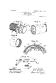
- Figure 1 is a perspective view showing our coupling, the two sections ,of hose being coupled.
- Fig. 2 is a longitudinal section through the device, the parts being coupled and locked in position.
- Fig. 3 is a section on the line 3 3 of Fig. 2.
- Fig. 4 is an end view of one of the Fig. 5 is a detail section on the line 5 5 of Fig. 2.
- Fig. 6 is a perspective vew showing one coupler member.
- FIG. 7 is a perspective view of the coupler member adapted to coact with the member shown in Fig. 6.
- Fig. 8 is a perspective view of a sleeve.
- Fig. 9 is an enlarged sectional View of the upper portion of Fig. 3.
- Fig. 10 is a perspective vew of the fastening and unlocking means, the various parts being shown detached.
- a and A represent sections of ahose to the end portions of which are secured sleeves B and B, respectively, which project beyond the hose-sections and are interiorly threaded adjacent their outer ends.
- a coupling member O which intermediate its ends is provided with an annular shoulder C, the said shoulder being threaded, as is also the coupling member, to the rear of the shoulder.
- the outer end of the shoulder C terminates in a flange C of B is in place the outer end of the sleeve bears on the flange O the threaded shoulder C engaging the interior threads of the sleeve,
- the flange C is recessed, as shown at D, at diametrically opposite points, and a bore D, formed in the front wall of each of these recesses, opens in the outer face of the flange into a groove D, one of these grooves being formed in the periphery of the coupling member O adjacent each recess D and extending circumferentially around the coupling member.
- a movable push-button D rests in each recess D, and each button carries a pin D which projects through and moves in the bore D, having a movement to and away from the axis of the coupling member.
- pawls or looking members E having an outer serrated edge. These pawls are pivoted between a bifur cated end portion of members E, which are secured by screws in the recesses and can therefore be readily removed for repair.
- the free end of each pawl is engaged by the adjacent pin D the outer end of which rests in a perforation in the pawl, and the pawl is normally pressed outwardly by a spring E shown in the drawings as a leaf-spring.
- a coacting coupler member F is preferably of less length than the coupler member 0 and is provided on its inner face with lugs F,- adapted to coact with the lugs D, said lugs interlocking, as described in the Letters Patent No. 782,555.
- Within the coupling member F we place toothed metal band F serrated and adapted to be engaged by the the lugs. Pressure on the buttons D is removed, and the springs E lift the pawls E outwardly into engagement with the teeth of the band F and lock the coupler members against further rotation with respect to each other. To unlock the coupling members, the above-described operation is reversed.
Description
No. 813,792. I PATENTED FEB. 27, 1905.
s. w. GOOOH & W. 0. LEASURE.
HOSE COUPLING.
APPLICATION FILED M.AR.6,1905.
'2 SHEETS-SHEET -1.
lA/l/E/VTORg W: G00am (j a 17%? We I B) W AT W/TIVE I 58' TOM/E78 No. 813,792. PATENTED FEB. 27, 1906. S. W. GOOGH 5: W. G. LEASURE.
HOSE COUPLING.
APPLICATION FILED MAR.G.1905.
2 SHEBT$SHEBT 2.
WITNESSES: INVENTORS 15. 7F. Gooczz,
coupling members.
UNITED STATES- PATENT OFFICE.
SHADRAOK W. GOOOH, OF BRIDGEPORT, OHIO, AND WILLIAM C. LEASURE, OF WHEELING, WEST VIRGINIA.
HOSE-COUPLING.
Specification of Letters Patent.
Patented. Feb. 27, 1906.
Application filed March 6, 1905- Serial No. 248,746.
Be it known that we, SHAnRAcK W. (300011, of Bridgeport, in the county of Belmont and State of Ohio, and WILLIAM C. LEASURE, of Wheeling, in the county of Ohio and State of West Virginia, citizens of the United States, have invented a new and useful Improvement in Hose-Couplings, of which the following is a specification.
This invention is an improvement on the hose-coupling for which Letters Patent No. 782,555 were granted to S. W. Gooch under date of February 14, 1905. i
This invention consists in certain nove features of securing the hose to the coupling members and for locking the said members in position when in engagement with each other.
In the accompanying drawings, Figure 1 is a perspective view showing our coupling, the two sections ,of hose being coupled. Fig. 2 is a longitudinal section through the device, the parts being coupled and locked in position. Fig. 3 is a section on the line 3 3 of Fig. 2. Fig. 4 is an end view of one of the Fig. 5 is a detail section on the line 5 5 of Fig. 2. Fig. 6 is a perspective vew showing one coupler member. Fig.
7 is a perspective view of the coupler member adapted to coact with the member shown in Fig. 6. Fig. 8 is a perspective view of a sleeve. Fig. 9 is an enlarged sectional View of the upper portion of Fig. 3. Fig. 10 is a perspective vew of the fastening and unlocking means, the various parts being shown detached.
In the drawings, A and A represent sections of ahose to the end portions of which are secured sleeves B and B, respectively, which project beyond the hose-sections and are interiorly threaded adjacent their outer ends. Into the hose-section A is forced the inner end portion of a coupling member O, which intermediate its ends is provided with an annular shoulder C, the said shoulder being threaded, as is also the coupling member, to the rear of the shoulder. The outer end of the shoulder C terminates in a flange C of B is in place the outer end of the sleeve bears on the flange O the threaded shoulder C engaging the interior threads of the sleeve,
while the outer face of the sleeve is substantially flush with the periphery of the flange O thus forming a smooth connection, the parts having the same exterior diameter. The flange C is recessed, as shown at D, at diametrically opposite points, and a bore D, formed in the front wall of each of these recesses, opens in the outer face of the flange into a groove D, one of these grooves being formed in the periphery of the coupling member O adjacent each recess D and extending circumferentially around the coupling member. A movable push-button D rests in each recess D, and each button carries a pin D which projects through and moves in the bore D, having a movement to and away from the axis of the coupling member.
In the grooves D, whose outer walls form a shoulder D are mounted pawls or looking members E, having an outer serrated edge. These pawls are pivoted between a bifur cated end portion of members E, which are secured by screws in the recesses and can therefore be readily removed for repair. The free end of each pawl is engaged by the adjacent pin D the outer end of which rests in a perforation in the pawl, and the pawl is normally pressed outwardly by a spring E shown in the drawings as a leaf-spring.
On the exterior of the coupling member O and in advance of the shoulder D are arranged circumferentially and spaced apart lugs D corresponding to the lugs B shown in the patent above referred to.
A coacting coupler member F is preferably of less length than the coupler member 0 and is provided on its inner face with lugs F,- adapted to coact with the lugs D, said lugs interlocking, as described in the Letters Patent No. 782,555. Within the coupling member F we place toothed metal band F serrated and adapted to be engaged by the the lugs. Pressure on the buttons D is removed, and the springs E lift the pawls E outwardly into engagement with the teeth of the band F and lock the coupler members against further rotation with respect to each other. To unlock the coupling members, the above-described operation is reversed.
Having thus fully described our coupling members, what we desire to secure by Letters Patent is 1. The combination with coacting coupler members, of a serrated band carried interiorly by one of said members, a spring-actuated pawl carried by the second member and adapted to. engage the band, radially-movable buttons carried by the second member, and pins carried by the buttons and adapted to move the said pawl.
2. The combination with coacting coupler members, one of said members having an interior band of teeth, the other member being recessed and circumferentially grooved adjacent the recesses, pawls pivotally mounted in the grooves, springs adapted to force the pawls outwardly into engagement with the teeth of the first-mentioned member, buttons movable radially in the recesses and pins caron the interior of one member, the other member being recessed and grooved at diametrically opposite points, pawls pivotally mounted in the grooves, springs arranged in the grooves and adapted to force the pawls outwardly, buttons movable inwardly and outwardly in the recesses, and pins carried by the buttons and secured to the pawls, as and for the purpose set forth.
SHADRACK W. GOOCH. WILLIAM C. LEASURE. Witnesses:
FRED A. HARPFER, Jr, LEROY O. LEASURE.
Priority Applications (1)
| Application Number | Priority Date | Filing Date | Title |
|---|---|---|---|
| US24874605A US813792A (en) | 1905-03-06 | 1905-03-06 | Hose-coupling. |
Applications Claiming Priority (1)
| Application Number | Priority Date | Filing Date | Title |
|---|---|---|---|
| US24874605A US813792A (en) | 1905-03-06 | 1905-03-06 | Hose-coupling. |
Publications (1)
| Publication Number | Publication Date |
|---|---|
| US813792A true US813792A (en) | 1906-02-27 |
Family
ID=2882272
Family Applications (1)
| Application Number | Title | Priority Date | Filing Date |
|---|---|---|---|
| US24874605A Expired - Lifetime US813792A (en) | 1905-03-06 | 1905-03-06 | Hose-coupling. |
Country Status (1)
| Country | Link |
|---|---|
| US (1) | US813792A (en) |
Cited By (7)
| Publication number | Priority date | Publication date | Assignee | Title |
|---|---|---|---|---|
| US4017937A (en) * | 1975-05-14 | 1977-04-19 | National Union Electric Corporation | Hose coupling for a suction cleaner |
| US6409221B1 (en) * | 1999-06-17 | 2002-06-25 | Phoenix Geometrix, Llc | Quick locking pipe joint for round, plain, or profiled pipe |
| US6520547B2 (en) | 2001-02-01 | 2003-02-18 | Phoenix Geometrix, Llc | Quick locking pipe joint for plain or profiled pipe |
| US20060103135A1 (en) * | 2004-11-18 | 2006-05-18 | Michael Scott | Exhaust pipe coupling |
| US20130125377A1 (en) * | 2011-11-23 | 2013-05-23 | Snap-Tite Technologies, Inc. | Coupling lock mechanism |
| US20130127155A1 (en) * | 2011-11-23 | 2013-05-23 | Parker-Hannifin Corporation | Coupling lock mechanism |
| US20230144489A1 (en) * | 2020-05-26 | 2023-05-11 | Bayerische Motoren Werke Aktiengesellschaft | Line Coupling Assembly |
-
1905
- 1905-03-06 US US24874605A patent/US813792A/en not_active Expired - Lifetime
Cited By (9)
| Publication number | Priority date | Publication date | Assignee | Title |
|---|---|---|---|---|
| US4017937A (en) * | 1975-05-14 | 1977-04-19 | National Union Electric Corporation | Hose coupling for a suction cleaner |
| US6409221B1 (en) * | 1999-06-17 | 2002-06-25 | Phoenix Geometrix, Llc | Quick locking pipe joint for round, plain, or profiled pipe |
| US6520547B2 (en) | 2001-02-01 | 2003-02-18 | Phoenix Geometrix, Llc | Quick locking pipe joint for plain or profiled pipe |
| US20060103135A1 (en) * | 2004-11-18 | 2006-05-18 | Michael Scott | Exhaust pipe coupling |
| US20130125377A1 (en) * | 2011-11-23 | 2013-05-23 | Snap-Tite Technologies, Inc. | Coupling lock mechanism |
| US20130127155A1 (en) * | 2011-11-23 | 2013-05-23 | Parker-Hannifin Corporation | Coupling lock mechanism |
| US8960726B2 (en) * | 2011-11-23 | 2015-02-24 | Parker-Hannifin Corporation | Coupling lock mechanism |
| US9217524B2 (en) * | 2011-11-23 | 2015-12-22 | Parker-Hannifin Corporation | Coupling lock mechanism |
| US20230144489A1 (en) * | 2020-05-26 | 2023-05-11 | Bayerische Motoren Werke Aktiengesellschaft | Line Coupling Assembly |
Similar Documents
| Publication | Publication Date | Title |
|---|---|---|
| US643358A (en) | Hose-coupling. | |
| US1199690A (en) | Fastener. | |
| US1885321A (en) | Pipe coupling | |
| US813792A (en) | Hose-coupling. | |
| US244804A (en) | gillespie | |
| US789541A (en) | Pipe-coupling. | |
| US464386A (en) | Hose-coupling | |
| US966529A (en) | Multiple bench-key. | |
| US1232733A (en) | Clasp. | |
| US807417A (en) | Coupling. | |
| US3537730A (en) | Quick flexible hose and/or pipe connection | |
| US1324654A (en) | Vania | |
| US1221935A (en) | Hose-coupling. | |
| US1362521A (en) | Coupling | |
| US832757A (en) | Hose-coupling. | |
| US454647A (en) | Manufacture of hose-couplings | |
| US1020258A (en) | Swivel-joint hose-coupling. | |
| US788600A (en) | Hose-coupling. | |
| US1080674A (en) | Threadless hose-coupling. | |
| US882643A (en) | Power-transmission device. | |
| US1002264A (en) | Hose-coupling. | |
| US948437A (en) | Hose-coupling. | |
| US893554A (en) | Hose-coupling. | |
| US868311A (en) | Hose-coupling. | |
| US266761A (en) | brown |