US8136851B2 - Access door with inside latch release - Google Patents
Access door with inside latch release Download PDFInfo
- Publication number
- US8136851B2 US8136851B2 US12/357,743 US35774309A US8136851B2 US 8136851 B2 US8136851 B2 US 8136851B2 US 35774309 A US35774309 A US 35774309A US 8136851 B2 US8136851 B2 US 8136851B2
- Authority
- US
- United States
- Prior art keywords
- door
- enclosure
- striker
- latch
- latching hook
- Prior art date
- Legal status (The legal status is an assumption and is not a legal conclusion. Google has not performed a legal analysis and makes no representation as to the accuracy of the status listed.)
- Expired - Fee Related, expires
Links
- 230000007246 mechanism Effects 0.000 claims abstract description 48
- 238000000034 method Methods 0.000 claims abstract description 33
- 238000010276 construction Methods 0.000 description 4
- 238000012423 maintenance Methods 0.000 description 3
- 238000002485 combustion reaction Methods 0.000 description 2
- 239000003546 flue gas Substances 0.000 description 2
- 239000002803 fossil fuel Substances 0.000 description 2
- 238000009434 installation Methods 0.000 description 2
- 239000000463 material Substances 0.000 description 2
- UGFAIRIUMAVXCW-UHFFFAOYSA-N Carbon monoxide Chemical compound [O+]#[C-] UGFAIRIUMAVXCW-UHFFFAOYSA-N 0.000 description 1
- 239000003245 coal Substances 0.000 description 1
- 230000000694 effects Effects 0.000 description 1
- 238000010304 firing Methods 0.000 description 1
- 239000007789 gas Substances 0.000 description 1
- 206010022000 influenza Diseases 0.000 description 1
- 239000012716 precipitator Substances 0.000 description 1
- 230000000284 resting effect Effects 0.000 description 1
- 239000002893 slag Substances 0.000 description 1
- 239000004071 soot Substances 0.000 description 1
- 239000003351 stiffener Substances 0.000 description 1
- 238000011179 visual inspection Methods 0.000 description 1
Images


Classifications
-
- E—FIXED CONSTRUCTIONS
- E05—LOCKS; KEYS; WINDOW OR DOOR FITTINGS; SAFES
- E05B—LOCKS; ACCESSORIES THEREFOR; HANDCUFFS
- E05B63/00—Locks or fastenings with special structural characteristics
- E05B63/24—Arrangements in which the fastening members which engage one another are mounted respectively on the wing and the frame and are both movable, e.g. for release by moving either of them
- E05B63/244—Arrangements in which the fastening members which engage one another are mounted respectively on the wing and the frame and are both movable, e.g. for release by moving either of them the striker being movable for latching, the bolt for unlatching, or vice versa
- E05B63/246—Emergency release from inside by releasing the striker
-
- F—MECHANICAL ENGINEERING; LIGHTING; HEATING; WEAPONS; BLASTING
- F22—STEAM GENERATION
- F22B—METHODS OF STEAM GENERATION; STEAM BOILERS
- F22B37/00—Component parts or details of steam boilers
- F22B37/02—Component parts or details of steam boilers applicable to more than one kind or type of steam boiler
- F22B37/22—Drums; Headers; Accessories therefor
- F22B37/221—Covers for drums, collectors, manholes or the like
-
- Y—GENERAL TAGGING OF NEW TECHNOLOGICAL DEVELOPMENTS; GENERAL TAGGING OF CROSS-SECTIONAL TECHNOLOGIES SPANNING OVER SEVERAL SECTIONS OF THE IPC; TECHNICAL SUBJECTS COVERED BY FORMER USPC CROSS-REFERENCE ART COLLECTIONS [XRACs] AND DIGESTS
- Y10—TECHNICAL SUBJECTS COVERED BY FORMER USPC
- Y10T—TECHNICAL SUBJECTS COVERED BY FORMER US CLASSIFICATION
- Y10T292/00—Closure fasteners
- Y10T292/08—Bolts
- Y10T292/1039—Swinging and camming
- Y10T292/1041—Rigid operating means
-
- Y—GENERAL TAGGING OF NEW TECHNOLOGICAL DEVELOPMENTS; GENERAL TAGGING OF CROSS-SECTIONAL TECHNOLOGIES SPANNING OVER SEVERAL SECTIONS OF THE IPC; TECHNICAL SUBJECTS COVERED BY FORMER USPC CROSS-REFERENCE ART COLLECTIONS [XRACs] AND DIGESTS
- Y10—TECHNICAL SUBJECTS COVERED BY FORMER USPC
- Y10T—TECHNICAL SUBJECTS COVERED BY FORMER US CLASSIFICATION
- Y10T292/00—Closure fasteners
- Y10T292/08—Bolts
- Y10T292/1043—Swinging
- Y10T292/1075—Operating means
- Y10T292/1078—Closure
-
- Y—GENERAL TAGGING OF NEW TECHNOLOGICAL DEVELOPMENTS; GENERAL TAGGING OF CROSS-SECTIONAL TECHNOLOGIES SPANNING OVER SEVERAL SECTIONS OF THE IPC; TECHNICAL SUBJECTS COVERED BY FORMER USPC CROSS-REFERENCE ART COLLECTIONS [XRACs] AND DIGESTS
- Y10—TECHNICAL SUBJECTS COVERED BY FORMER USPC
- Y10T—TECHNICAL SUBJECTS COVERED BY FORMER US CLASSIFICATION
- Y10T292/00—Closure fasteners
- Y10T292/20—Clamps
- Y10T292/221—Screw and nut
-
- Y—GENERAL TAGGING OF NEW TECHNOLOGICAL DEVELOPMENTS; GENERAL TAGGING OF CROSS-SECTIONAL TECHNOLOGIES SPANNING OVER SEVERAL SECTIONS OF THE IPC; TECHNICAL SUBJECTS COVERED BY FORMER USPC CROSS-REFERENCE ART COLLECTIONS [XRACs] AND DIGESTS
- Y10—TECHNICAL SUBJECTS COVERED BY FORMER USPC
- Y10T—TECHNICAL SUBJECTS COVERED BY FORMER US CLASSIFICATION
- Y10T292/00—Closure fasteners
- Y10T292/68—Keepers
- Y10T292/696—With movable dog, catch or striker
- Y10T292/702—Pivoted or swinging
Definitions
- the present invention relates generally to a door which is used to gain access to the interior of a steam generator and its related equipment, and more particularly to a door latch which can be quickly released by a person from within the steam generator or related equipment.
- Access doors for steam generators and related equipment e.g., flues, ducts, windboxes, hoppers, air heaters, penthouses, vestibules, precipitators, baghouses, scrubbers, etc.
- Steam generators and related equipment e.g., flues, ducts, windboxes, hoppers, air heaters, penthouses, vestibules, precipitators, baghouses, scrubbers, etc.
- Installation and maintenance personnel need such access for movement of equipment and materials into and out of the steam generator and related equipment for installation, repair, and maintenance of the internal components and surfaces of the steam generator and related equipment.
- latch mechanisms which can be released from the inside of a door have been provided for freezers, refrigerators and the like, where the interiors are kept under a relatively clean environment.
- Such latch mechanisms are of multipart construction whose parts are automatically returned to the normal operative position after the door has been opened from the inside. See for example, U.S. Pat. Nos. 2,747,906; 2,849,250; 2,966,864; 3,936,086; and 4,372,591.
- Prior art latches which allow the opening of an access door from the indoor side are complex in construction and operation and may be difficult to manipulate in the dark and cramped quarters of a steam generator.
- a further aspect of the present invention is to provide an access door with an indoor latch release capable of withstanding the harsh environment of an operating fossil fuel fired steam generator.
- Another aspect of the present invention is to provide a latch structure requiring only a turn of a latch handle from inside the access door to release the striker and allow the access door to be pushed open.
- a further aspect of the present invention is to provide a rugged and durable latch structure including a striker releasable from inside the steam generator, and which is relatively inexpensive to fabricate and easy to assemble and manipulate.
- the present invention is drawn to a steam generator access door latch mechanism structured for quick release, if necessary, from within the steam generator.
- the quick-release latch mechanism must also be capable to withstand the harsh environment of an operating steam generator.
- the present invention accomplishes this by providing a latch mechanism which is simply comprised of two essential parts; i.e., a latch handle and a striker. Both the latch handle and the striker are disengaged and separately removed as the access door is being opened, and are manually returned to the normal operative position as the door is being closed.
- the latch handle and the striker are available for visual inspection and, if necessary, repair or replacement by maintenance personnel, each time that the access door is opened.
- a quick-release latch mechanism for use with an access door for a walled enclosure.
- the access door is pivotably mounted on a door frame for swinging between open and closed positions.
- the quick-release latch mechanism includes a striker having a proximal end located on the outer side of the door and a distal end slidably extending into the enclosure through a corresponding slot formed in the door frame.
- a keeper is located within the enclosure adjacent the inner side of the door and adapted to releasably engage and be captively held by the striker when the door is in the closed position. If necessary, the access door can be quickly unlatched from within the enclosure by manually rotating the keeper away from the enclosure wall to disengage and cause removal of the striker from the slot as the door is manually pushed open from within the enclosure.
- the keeper is in the form of a latch handle having a forked cam at one end and a pistol-type grip at the other end.
- a catch pin is mounted in the forked cam end of the latch handle.
- the striker is formed with a latching hook at its distal end and a pivotably mounted threaded member at its proximal end.
- the latching hook includes a notch shaped to receive the catch pin of the latch handle.
- At least one yoke extends across the outer side of the access door, and has one end hinged to brackets secured to the door frame and the other end notched to engage the threaded member of the striker.
- a turning handle is threadably engaged with the threaded member at the proximal end of the striker to apply inward pressure to the exterior of the door by rotating the turning handle clockwise, while the door is in the closed position.
- the pistol-type grip of the latch handle abuts or bears against the enclosure wall, and the forked cam end and catch pin are engaged with the striker latching hook.
- the access door can be readily opened, from within the enclosure, by manually rotating the latch handle away from the enclosure wall with an angle of rotation of about 90 degrees along a plane perpendicular to the wall to effect the release of the catch pin and disengagement of the latch handle from the striker latching hook thereby allowing the door to be manually pushed to the open position.
- another aspect of the present invention is drawn to a method of latching and unlatching a walled enclosure access door for quick release from within the enclosure, the method comprising the steps of pivotably mounting the door on a door frame for swinging the door between open and closed positions; providing a latch handle inside the enclosure, the latch handle having a pistol-type grip at one end and a forked cam at the other end with a catch pin mounted therein; providing a striker with a latching hook at one end and a pivotable threaded member at the other end; inserting the latching hook end into the enclosure; positioning the latch handle with the pistol-type grip end abutting the inside of the enclosure wall and the catch pin engaging the latching hook; pushing the door to its closed position for engagement with the threaded member of the striker; applying inward pressure to the exterior of the door while the door is in the closed position; and, if necessary, unlatching the door from within the enclosure by rotating the latch handle away from the enclosure wall thereby causing the catch pin to disengage itself from
- Another aspect of the invention involves the method of latching and unlatching a walled enclosure access door, wherein the step of unlatching the door includes rotating a quick-release latch handle 90 degrees from within the enclosure wall.
- Yet another aspect of the invention involves the method of latching and unlatching a walled enclosure access door, including the step of forming a slot in the door frame such that the latching hook is free to move into and out of the enclosure.
- Yet still another aspect of the invention involves the method of latching and unlatching a walled enclosure access door, including the step of mounting a yoke onto the door.
- Still another aspect of the invention involves the method of latching and unlatching a walled enclosure access door, wherein the step of applying inward pressure to the exterior of the door includes meshing the yoke with the threaded member of the striker.
- a further aspect of the invention involves the method of latching and unlatching a walled enclosure access door, wherein the step of meshing the yoke with the threaded member of the striker includes turning means threadably engaged with the threaded member of the striker.
- a still further aspect of the invention involves the method of latching and unlatching a walled enclosure access door, including the step of rotating the turning means clockwise to apply inward pressure to the exterior of the door.
- FIG. 1 is a perspective view of a closed access door equipped with the quick-release latch mechanism of the present invention in the latched state, as seen from the indoor side;
- FIG. 2 is a perspective view of a closed access door equipped with the quick-release latch mechanism of the present invention in the latched state, as seen from the outdoor side;
- FIG. 3 is a perspective view of an access door equipped with the quick-release latch mechanism of the present invention in the process of being unlatched from the indoor side;
- FIG. 4 is a perspective view of an access door equipped with the quick-release latch mechanism of the present invention in the unlatched state and in the process of being opened from the indoor side;
- FIG. 5 is a perspective view of an access door equipped with the quick-release latch mechanism of the present invention in the unlatched state and in the process of being opened from the indoor side, as seen from the outdoor side;
- FIG. 6 is a perspective view of an access door equipped with the quick-release latch mechanism of the present invention in the unlatched state and in the process of being closed, as seen from the outdoor side;
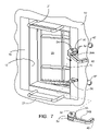
- FIG. 7 is a perspective view of an access door equipped with the quick-release latch mechanism of the present invention in the process of being latched, as seen from the indoor side;
- FIG. 8 is a cut away top view of the quick-release latch mechanism of the present invention in the latched state.
- FIG. 9 is a cut away top view of the quick-release latch mechanism of the present invention in the process of being unlatched.
- FIG. 1 there is shown in fragmentary fashion an upright wall 10 of a steam generator enclosure or passageway 12 which is provided with a wall opening 14 through which access may be had to the interior of the enclosure 12 .
- the opening 14 is of generally rectangular configuration, elongated in a vertical direction, and is defined by a door frame 16 provided in the upright wall 10 .
- a door casing 18 is mounted on the door frame 16 .
- a rectangular access door 20 overlaps the entire periphery of the casing 18 and is adapted to abut the casing 18 when the access door 20 is fully closed.
- the door 20 is reinforced by cross-stiffeners 19 affixed to the door side facing the interior of enclosure 12 .
- Grab bars 21 are mounted on the door frame 16 inside and outside of the enclosure 12 for ease of exit from and entry into the enclosure 12 .
- a pair of spaced upper and lower parallel horizontal yokes 22 span the access door 20 and the door casing 18 .
- the yokes 22 are in the form of rigid channel members having a generally rectangular cross-section, and are bolted to corresponding brackets 24 which are in turn fixedly attached to the access door 20 .
- One end of each of the yokes 22 is hingedly secured about a corresponding pivot pin 26 mounted on a pair of support brackets 28 connected to the door frame 16 .
- Each of the yokes 22 is configured with a notch 29 at the other end, as shown in FIG. 6 .
- a quick-release latch mechanism 30 shown in FIGS. 8 and 9 , with components thereof, particularly strikers 32 A-B and keepers 34 A-B being shown throughout the drawings.
- the strikers 32 A-B include a latching hook 36 formed at its distal end, and a coupler or clevis 40 formed at its proximal end.
- the latching hook 36 is configured with a notch 42 formed therein, and shown in FIGS. 8 and 9 .
- the clevis 40 is pivotably connected to one end of a threaded member 44 by a pivot pin 46 .
- a turning handle 47 is threadably engaged with the threaded member 44 .
- Each of the keepers or latch handles 34 A-B is formed with a pistol-type grip 48 at one end and a forked cam 50 at the other end.
- the forked cam 50 includes a pair of supporting legs 52 which are spaced sufficiently apart so as to pivotably straddle the corresponding latching hook 36 of striker 32 A-B.
- a catch pin 54 is connected to the supporting legs 52 of the forked cam 50 .
- the process of unlatching the access door 20 from the inside of enclosure 12 is effected by manually rotating the latch handles or keepers 34 A-B away from the enclosure wall 10 along a plane perpendicular to the wall 10 until the latch handles 34 A-B are disengaged from the corresponding latch strikers 32 A-B.
- FIG. 1 shows the access door 20 in the closed position as seen from the inside of enclosure 12 .
- Each of the of latch handles 34 A-B has its pistol-type grip 48 abutting or bearing against the enclosure wall 10 and its forked cam legs 52 pivotably straddling the latching hook 36 .
- FIG. 2 shows the access door 20 in the closed position as seen from the outside of enclosure 12 .
- the threaded members 44 of strikers 32 A-B are engaged with the notched ends 29 of yokes 22 .
- the turning handles 47 are rotated clockwise to apply inward pressure to the outer face or side of the closed access door 20 , and to thus secure the door 20 in its closed position.
- FIG. 3 shows the access door 20 in the process of being manually unlatched from the inside of enclosure 12 .
- the upper latch handle 34 A is in its engaged position with its pistol-type grip 48 abutting the enclosure wall 10 and its forked cam legs 52 pivotably straddled about the latching hook 36 .
- the lower latch handle 34 B is in the process of being manually disengaged from the latching hook 36 by the rotating of the pistol-type grip 48 away from the enclosure wall 10 , thereby causing the cam-action of the forked cam 50 to disengage the catch pin 54 from the latching hook 36 .
- the same procedure is followed in the manual disengagement of the upper latch handle 34 A from the latching hook 36 in order to complete the unlatching of the access door 20 .
- FIG. 4 shows the unlatched access door 20 as seen from the inside of enclosure 12 .
- the access door 20 is partially open and on its way to being manually pushed to a fully opened position.
- the latch handles 34 A-B have been manually disengaged from the respective latching hooks 36 , thereby unlatching the access door 20 .
- FIG. 5 shows the unlatched access door 20 as seen from the outside of enclosure 12 .
- the access door 20 is partially open and on its way to being manually pushed to a fully opened position.
- the latch hooks 36 are forced out of the enclosure 12 through the door frame slots 56 as the latch strikers 32 A-B are moved along with the access door 20 which is being pushed open from the inside of enclosure 12 .
- a resilient, high-temperature gasket 57 is provided for each frame slot 56 as shown. By being resilient or slightly compressible, the gaskets 57 provide a positive “feel” or indication as the cam-action engagement of the latch handles 34 A and 34 b to the latching hooks 36 takes place.
- FIG. 6 shows the access door 20 in the process of being manually closed, as seen from the outside of enclosure 12 .
- the latching hooks 36 of latch strikers 32 A-B are slidably inserted through door frame slots 56 into the enclosure 12 , and the turning handles 47 and the threaded member 44 are pivoted clear of the closing path of the access door 20 .
- FIG. 7 shows the access door 20 in the process of being closed, as seen from the inside of enclosure 12 .
- the latch handles 34 A-B are manually placed into the enclosure 12 through the open access door 20 .
- the latch handle 34 A is being positioned so as to have the forked cam legs 52 pivotably straddling the latching hook 36 with the catch pin 54 resting in the latching hook notch 42 , and the pistol-type grip 48 being turned such that it will abut the enclosure wall 10 , as shown in FIGS. 1 and 3 .
- the same procedure is followed in the manual engagement of the lower latch handle 34 B with the latching hook 36 .
- the turning handles 47 and the threaded members 44 are pivoted to engage the yoke notches 29 .
- the turning handles 47 are rotated to apply inward pressure on the exterior face or side of the access door 20 , to secure the latching of the door 20 in its closed position, as shown in FIG. 2 .
- FIG. 8 shows the latching mechanism 30 in a latched position.
- the latch striker 32 has its latching hook 36 extending into the enclosure 12 and in latched engagement with the cam 50 of latch handle 34 whose catch pin 54 rests in the notch 42 of latching hook 36 .
- the latch handle pistol-type grip 48 abuts the enclosure wall 10 .
- FIG. 9 shows the latching mechanism 30 in the process of being unlatched from the inside of enclosure 12 .
- the rotating of the latch handle 34 about 90 degrees from the enclosure wall 10 along a plane perpendicular to the wall 10 causes the cam-action of the latch handle cam 50 to move the catch pin 54 out of the notch 42 of the striker latching hook 36 .
- the thus unlatched handle 34 is manually removed from engagement with the latch striker 32 .
Abstract
Description
Claims (32)
Priority Applications (1)
| Application Number | Priority Date | Filing Date | Title |
|---|---|---|---|
| US12/357,743 US8136851B2 (en) | 2009-01-22 | 2009-01-22 | Access door with inside latch release |
Applications Claiming Priority (1)
| Application Number | Priority Date | Filing Date | Title |
|---|---|---|---|
| US12/357,743 US8136851B2 (en) | 2009-01-22 | 2009-01-22 | Access door with inside latch release |
Publications (2)
| Publication Number | Publication Date |
|---|---|
| US20100181781A1 US20100181781A1 (en) | 2010-07-22 |
| US8136851B2 true US8136851B2 (en) | 2012-03-20 |
Family
ID=42336326
Family Applications (1)
| Application Number | Title | Priority Date | Filing Date |
|---|---|---|---|
| US12/357,743 Expired - Fee Related US8136851B2 (en) | 2009-01-22 | 2009-01-22 | Access door with inside latch release |
Country Status (1)
| Country | Link |
|---|---|
| US (1) | US8136851B2 (en) |
Cited By (2)
| Publication number | Priority date | Publication date | Assignee | Title |
|---|---|---|---|---|
| US9021744B2 (en) * | 2012-08-17 | 2015-05-05 | Michael Wayne Kirkpatrick | Heat recovery steam generator access door kit |
| US9909354B1 (en) * | 2012-08-17 | 2018-03-06 | Michael Wayne Kirkpatrick | Door apparatus with boom assembly |
Families Citing this family (2)
| Publication number | Priority date | Publication date | Assignee | Title |
|---|---|---|---|---|
| DE202015005831U1 (en) * | 2015-08-19 | 2016-11-23 | Nilfisk A/S | Closure system for a filter flap in an industrial extraction system |
| USD837844S1 (en) * | 2017-04-13 | 2019-01-08 | Peter Simpson | Air lock access door |
Citations (40)
| Publication number | Priority date | Publication date | Assignee | Title |
|---|---|---|---|---|
| US472938A (en) * | 1892-04-12 | Stillman m | ||
| US566184A (en) * | 1896-08-18 | Eugene jauss | ||
| US1028452A (en) * | 1912-03-14 | 1912-06-04 | Cowles & Co C | Window-fastener. |
| US1646636A (en) * | 1926-06-09 | 1927-10-25 | Ira T Swartz | Fastening clamp |
| US1666945A (en) * | 1926-08-02 | 1928-04-24 | Sekyer Carl Petersen | Sash fastener |
| US1912850A (en) * | 1930-12-29 | 1933-06-06 | Stuber & Kuck Co | Clamp for receptacle covers |
| US2150851A (en) * | 1937-12-13 | 1939-03-14 | Thompson Foster John | Casement window fastener |
| US2177942A (en) * | 1937-03-27 | 1939-10-31 | Lang Albert | Window screen hanger |
| US2639176A (en) * | 1951-04-25 | 1953-05-19 | Michael J Montalbano | Sash fastening means |
| US2746782A (en) * | 1952-03-01 | 1956-05-22 | Imp Cold Storage And Supply Co | Releasable door fastening |
| US2747906A (en) | 1952-10-03 | 1956-05-29 | Horace Fong | Inside control for refrigerator door latches |
| US2750219A (en) * | 1952-07-11 | 1956-06-12 | Admiral Corp | Latch mechanism |
| US2753207A (en) * | 1953-08-24 | 1956-07-03 | Miner Inc W H | Keeper for door fasteners |
| US2775001A (en) * | 1953-05-05 | 1956-12-25 | Carrier Corp | Window locking assembly |
| US2849250A (en) | 1955-09-27 | 1958-08-26 | Gen Electric | Emergency release latch mechanism |
| US2966864A (en) | 1957-12-12 | 1961-01-03 | Elmer R Weaver | Refrigerator lock with inside release |
| US3151903A (en) * | 1960-08-18 | 1964-10-06 | Effner George | Lid-lock for pressure vessels |
| US3346288A (en) * | 1965-09-01 | 1967-10-10 | John P Cosentino | Safety lock means |
| US3424339A (en) * | 1967-02-20 | 1969-01-28 | Case Co J I | Wire container |
| US3560038A (en) * | 1968-12-18 | 1971-02-02 | Dzus Fastener Co | Lever actuated fastener assembly |
| US3811718A (en) * | 1972-08-10 | 1974-05-21 | Truth Inc | Sash lock |
| US3936086A (en) | 1974-06-07 | 1976-02-03 | Kason Hardware Corporation | Inside safety release latch device |
| US4303264A (en) * | 1978-08-14 | 1981-12-01 | Yoshida Kogyo K.K. | Window latch |
| US4331354A (en) * | 1980-06-16 | 1982-05-25 | Helding Curtis L | Door push bar lock-out retainer |
| US4372591A (en) | 1978-12-26 | 1983-02-08 | Standard-Keil Hardware Mfg. Co., A Division Of Buildex Inc. | Safety latch |
| US4803808A (en) * | 1987-06-08 | 1989-02-14 | Aug. Winkhaus Gmbh & Co. Kg | Window including a casement frame pivoted to a stationary frame and a locking device for the casement frame mounted on the stationary frame |
| US5197226A (en) * | 1991-07-25 | 1993-03-30 | The Babcock & Wilcox Company | Access door with safety latch for pressurized air chambers |
| US5462249A (en) * | 1994-01-25 | 1995-10-31 | Calzone; Ronald J. | Clamp for securing trailer ramp in transport position |
| US5741031A (en) * | 1996-03-18 | 1998-04-21 | Truth Hardware Corporation | Concealed window lock with detachable handle and escutcheon |
| US6109668A (en) * | 1998-02-27 | 2000-08-29 | Demarco; Giuseppe | Window lock |
| US6139074A (en) * | 1999-05-14 | 2000-10-31 | Triodyne Wangler Construction Specialties, Llc | Window locking system |
| US6412834B1 (en) * | 1999-10-18 | 2002-07-02 | Interlock Group Limited | Window fastener |
| US20020089190A1 (en) * | 2001-01-05 | 2002-07-11 | Apple Computer, Inc. | Locking system for a portable computer |
| US20030026084A1 (en) * | 2001-08-03 | 2003-02-06 | Lauchner Craig E. | Cable management arm with trough and breakaway feature |
| US6546671B2 (en) * | 2001-08-01 | 2003-04-15 | Weather Shield Mfg., Inc. | Tilt window latch assembly |
| US6644884B2 (en) * | 2001-02-28 | 2003-11-11 | Roro Frank Of America, Inc. | Rotational spring clip for connecting a male component to a female component |
| US7168576B2 (en) * | 2003-03-21 | 2007-01-30 | Dell Products L.P. | Tool-less cable management attachment bracket and method of use |
| US20070158956A1 (en) * | 2005-10-28 | 2007-07-12 | Jui Hung Refrigeration Technology Co., Ltd. | Pressurized handle set |
| US7617707B2 (en) * | 2006-09-29 | 2009-11-17 | Fanny Chiang | Window-locking assembly |
| US20110056139A1 (en) * | 2008-03-26 | 2011-03-10 | Vkr Holding A/S | Outwardly opening for a window or door assemble |
-
2009
- 2009-01-22 US US12/357,743 patent/US8136851B2/en not_active Expired - Fee Related
Patent Citations (40)
| Publication number | Priority date | Publication date | Assignee | Title |
|---|---|---|---|---|
| US566184A (en) * | 1896-08-18 | Eugene jauss | ||
| US472938A (en) * | 1892-04-12 | Stillman m | ||
| US1028452A (en) * | 1912-03-14 | 1912-06-04 | Cowles & Co C | Window-fastener. |
| US1646636A (en) * | 1926-06-09 | 1927-10-25 | Ira T Swartz | Fastening clamp |
| US1666945A (en) * | 1926-08-02 | 1928-04-24 | Sekyer Carl Petersen | Sash fastener |
| US1912850A (en) * | 1930-12-29 | 1933-06-06 | Stuber & Kuck Co | Clamp for receptacle covers |
| US2177942A (en) * | 1937-03-27 | 1939-10-31 | Lang Albert | Window screen hanger |
| US2150851A (en) * | 1937-12-13 | 1939-03-14 | Thompson Foster John | Casement window fastener |
| US2639176A (en) * | 1951-04-25 | 1953-05-19 | Michael J Montalbano | Sash fastening means |
| US2746782A (en) * | 1952-03-01 | 1956-05-22 | Imp Cold Storage And Supply Co | Releasable door fastening |
| US2750219A (en) * | 1952-07-11 | 1956-06-12 | Admiral Corp | Latch mechanism |
| US2747906A (en) | 1952-10-03 | 1956-05-29 | Horace Fong | Inside control for refrigerator door latches |
| US2775001A (en) * | 1953-05-05 | 1956-12-25 | Carrier Corp | Window locking assembly |
| US2753207A (en) * | 1953-08-24 | 1956-07-03 | Miner Inc W H | Keeper for door fasteners |
| US2849250A (en) | 1955-09-27 | 1958-08-26 | Gen Electric | Emergency release latch mechanism |
| US2966864A (en) | 1957-12-12 | 1961-01-03 | Elmer R Weaver | Refrigerator lock with inside release |
| US3151903A (en) * | 1960-08-18 | 1964-10-06 | Effner George | Lid-lock for pressure vessels |
| US3346288A (en) * | 1965-09-01 | 1967-10-10 | John P Cosentino | Safety lock means |
| US3424339A (en) * | 1967-02-20 | 1969-01-28 | Case Co J I | Wire container |
| US3560038A (en) * | 1968-12-18 | 1971-02-02 | Dzus Fastener Co | Lever actuated fastener assembly |
| US3811718A (en) * | 1972-08-10 | 1974-05-21 | Truth Inc | Sash lock |
| US3936086A (en) | 1974-06-07 | 1976-02-03 | Kason Hardware Corporation | Inside safety release latch device |
| US4303264A (en) * | 1978-08-14 | 1981-12-01 | Yoshida Kogyo K.K. | Window latch |
| US4372591A (en) | 1978-12-26 | 1983-02-08 | Standard-Keil Hardware Mfg. Co., A Division Of Buildex Inc. | Safety latch |
| US4331354A (en) * | 1980-06-16 | 1982-05-25 | Helding Curtis L | Door push bar lock-out retainer |
| US4803808A (en) * | 1987-06-08 | 1989-02-14 | Aug. Winkhaus Gmbh & Co. Kg | Window including a casement frame pivoted to a stationary frame and a locking device for the casement frame mounted on the stationary frame |
| US5197226A (en) * | 1991-07-25 | 1993-03-30 | The Babcock & Wilcox Company | Access door with safety latch for pressurized air chambers |
| US5462249A (en) * | 1994-01-25 | 1995-10-31 | Calzone; Ronald J. | Clamp for securing trailer ramp in transport position |
| US5741031A (en) * | 1996-03-18 | 1998-04-21 | Truth Hardware Corporation | Concealed window lock with detachable handle and escutcheon |
| US6109668A (en) * | 1998-02-27 | 2000-08-29 | Demarco; Giuseppe | Window lock |
| US6139074A (en) * | 1999-05-14 | 2000-10-31 | Triodyne Wangler Construction Specialties, Llc | Window locking system |
| US6412834B1 (en) * | 1999-10-18 | 2002-07-02 | Interlock Group Limited | Window fastener |
| US20020089190A1 (en) * | 2001-01-05 | 2002-07-11 | Apple Computer, Inc. | Locking system for a portable computer |
| US6644884B2 (en) * | 2001-02-28 | 2003-11-11 | Roro Frank Of America, Inc. | Rotational spring clip for connecting a male component to a female component |
| US6546671B2 (en) * | 2001-08-01 | 2003-04-15 | Weather Shield Mfg., Inc. | Tilt window latch assembly |
| US20030026084A1 (en) * | 2001-08-03 | 2003-02-06 | Lauchner Craig E. | Cable management arm with trough and breakaway feature |
| US7168576B2 (en) * | 2003-03-21 | 2007-01-30 | Dell Products L.P. | Tool-less cable management attachment bracket and method of use |
| US20070158956A1 (en) * | 2005-10-28 | 2007-07-12 | Jui Hung Refrigeration Technology Co., Ltd. | Pressurized handle set |
| US7617707B2 (en) * | 2006-09-29 | 2009-11-17 | Fanny Chiang | Window-locking assembly |
| US20110056139A1 (en) * | 2008-03-26 | 2011-03-10 | Vkr Holding A/S | Outwardly opening for a window or door assemble |
Cited By (3)
| Publication number | Priority date | Publication date | Assignee | Title |
|---|---|---|---|---|
| US9021744B2 (en) * | 2012-08-17 | 2015-05-05 | Michael Wayne Kirkpatrick | Heat recovery steam generator access door kit |
| US9500359B1 (en) | 2012-08-17 | 2016-11-22 | Wk Enterprises, Llc | Heat recovery steam generator access door kit |
| US9909354B1 (en) * | 2012-08-17 | 2018-03-06 | Michael Wayne Kirkpatrick | Door apparatus with boom assembly |
Also Published As
| Publication number | Publication date |
|---|---|
| US20100181781A1 (en) | 2010-07-22 |
Similar Documents
| Publication | Publication Date | Title |
|---|---|---|
| US8136851B2 (en) | Access door with inside latch release | |
| TWI745803B (en) | Bracket for mounting an item to a cross member and method of reorienting a bracket mounted on a cross member | |
| JP2008298069A (en) | Nacelle, gas turbine engine and maintenance method of gas turbine engine | |
| US20080305448A1 (en) | Safety door for rotary kiln | |
| JP6956724B2 (en) | Combustor assembly lift system, and methods for installing and removing the combustor assembly using the combustor assembly lift system | |
| US10219653B1 (en) | Foldable and portable grilling apparatus | |
| KR101734032B1 (en) | Pyrolysis gasifier | |
| JP3214456U (en) | Ventilation device | |
| KR101745852B1 (en) | Pyrolysis gasifier | |
| EP3022498A1 (en) | A duct member and closure assembly for a duct member | |
| KR100197024B1 (en) | Door structure for coming in and out to the inner part of a boiler | |
| CN113446614B (en) | Flue gas waste heat recovery device | |
| RU225583U1 (en) | Burglar-resistant docking unit for gas and smoke removal | |
| RU76914U1 (en) | GATEWAY DEVICE FOR LOADING A SOLID FUEL IN A GAS GENERATOR OPERATING UNDER PRESSURE | |
| KR100580102B1 (en) | Observation Port of Furnace | |
| CN208652521U (en) | A kind of horizontal condensing steam boiler front smoke box | |
| CN204201975U (en) | Self closing door fume-exhausting hood and the range hood applied thereof | |
| CN220017368U (en) | Heat recovery device | |
| CN210568468U (en) | Inlet and outlet structure of regenerative incinerator | |
| JP2001221884A (en) | Method for overhauling of swing support part of airlock door for staff | |
| CN104075361A (en) | Automatic air door range hood cover and range hood applying range hood cover | |
| JP7173675B2 (en) | Inspection sight glass | |
| CN209621886U (en) | A kind of shaft coupling action shield | |
| BE1019196A5 (en) | MULTIFUNCTIONAL FIREPLACE WITH A SMOKE DEFLECTION DEVICE. | |
| CN208295136U (en) | One kind being easy to closed smoke exhaust fire damper |
Legal Events
| Date | Code | Title | Description |
|---|---|---|---|
| AS | Assignment |
Owner name: BABCOCK & WILCOX POWER GENERATION GROUP, INC., OHI Free format text: ASSIGNMENT OF ASSIGNORS INTEREST;ASSIGNOR:NELSON, NORMAN D.;REEL/FRAME:022142/0311 Effective date: 20090122 |
|
| AS | Assignment |
Owner name: BANK OF AMERICA, N.A., AS ADMINISTRATIVE AGENT, CA Free format text: NOTICE OF GRANT OF SECURITY INTEREST IN PATENTS;ASSIGNOR:BABCOCK & WILCOX POWER GENERATION GROUP, INC. (F.K.A. THE BABCOCK & WILCOX COMPANY);REEL/FRAME:025066/0080 Effective date: 20100503 |
|
| STCF | Information on status: patent grant |
Free format text: PATENTED CASE |
|
| AS | Assignment |
Owner name: BANK OF AMERICA, N.A., AS ADMINISTRATIVE AGENT, CA Free format text: SECURITY INTEREST;ASSIGNOR:BABCOCK & WILCOX POWER GENERATION GROUP, INC.;REEL/FRAME:033380/0744 Effective date: 20140624 |
|
| AS | Assignment |
Owner name: BANK OF AMERICA, N.A., AS ADMINISTRATIVE AGENT, CA Free format text: SECURITY INTEREST;ASSIGNOR:BABCOCK & WILCOX POWER GENERATION GROUP, INC. (TO BE RENAMED THE BABCOCK AND WILCOX COMPANY);REEL/FRAME:036201/0598 Effective date: 20150630 |
|
| FPAY | Fee payment |
Year of fee payment: 4 |
|
| AS | Assignment |
Owner name: THE BABCOCK & WILCOX COMPANY, OHIO Free format text: CHANGE OF NAME;ASSIGNOR:BABCOCK & WILCOX POWER GENERATION GROUP, INC.;REEL/FRAME:036675/0434 Effective date: 20150630 |
|
| AS | Assignment |
Owner name: LIGHTSHIP CAPITAL LLC, NEW YORK Free format text: SECURITY INTEREST;ASSIGNORS:THE BABCOCK & WILCOX COMPANY;DIAMOND POWER INTERNATIONAL, LLC;BABCOCK & WILCOX MEGTEC, LLC;AND OTHERS;REEL/FRAME:043515/0001 Effective date: 20170809 |
|
| AS | Assignment |
Owner name: MEGTEC TURBOSONIC TECHNOLOGIES, INC., NORTH CAROLINA Free format text: RELEASE BY SECURED PARTY;ASSIGNOR:LIGHTSHIP CAPITAL LLC;REEL/FRAME:046182/0829 Effective date: 20180504 Owner name: BABCOCK & WILCOX ENTERPRISES, INC., NORTH CAROLINA Free format text: RELEASE BY SECURED PARTY;ASSIGNOR:LIGHTSHIP CAPITAL LLC;REEL/FRAME:046182/0829 Effective date: 20180504 Owner name: DIAMOND POWER INTERNATIONAL, LLC, NORTH CAROLINA Free format text: RELEASE BY SECURED PARTY;ASSIGNOR:LIGHTSHIP CAPITAL LLC;REEL/FRAME:046182/0829 Effective date: 20180504 Owner name: BABCOCK & WILCOX UNIVERSAL, INC., NORTH CAROLINA Free format text: RELEASE BY SECURED PARTY;ASSIGNOR:LIGHTSHIP CAPITAL LLC;REEL/FRAME:046182/0829 Effective date: 20180504 Owner name: BABCOCK & WILCOX TECHNOLOGY, LLC, NORTH CAROLINA Free format text: RELEASE BY SECURED PARTY;ASSIGNOR:LIGHTSHIP CAPITAL LLC;REEL/FRAME:046182/0829 Effective date: 20180504 Owner name: MEGTEC TURBOSONIC TECHNOLOGIES, INC., NORTH CAROLI Free format text: RELEASE BY SECURED PARTY;ASSIGNOR:LIGHTSHIP CAPITAL LLC;REEL/FRAME:046182/0829 Effective date: 20180504 Owner name: BABCOCK & WILCOX MEGTEC, LLC, NORTH CAROLINA Free format text: RELEASE BY SECURED PARTY;ASSIGNOR:LIGHTSHIP CAPITAL LLC;REEL/FRAME:046182/0829 Effective date: 20180504 Owner name: THE BABCOCK & WILCOX COMPANY, NORTH CAROLINA Free format text: RELEASE BY SECURED PARTY;ASSIGNOR:LIGHTSHIP CAPITAL LLC;REEL/FRAME:046182/0829 Effective date: 20180504 |
|
| MAFP | Maintenance fee payment |
Free format text: PAYMENT OF MAINTENANCE FEE, 8TH YEAR, LARGE ENTITY (ORIGINAL EVENT CODE: M1552); ENTITY STATUS OF PATENT OWNER: LARGE ENTITY Year of fee payment: 8 |
|
| AS | Assignment |
Owner name: BABCOCK & WILCOX MEGTEC, LLC, WISCONSIN Free format text: RELEASE BY SECURED PARTY;ASSIGNOR:BANK OF AMERICA, N.A.;REEL/FRAME:057337/0823 Effective date: 20210630 Owner name: SOFCO-EFS HOLDINGS LLC, OHIO Free format text: RELEASE BY SECURED PARTY;ASSIGNOR:BANK OF AMERICA, N.A.;REEL/FRAME:057337/0823 Effective date: 20210630 Owner name: BABCOCK & WILCOX TECHNOLOGY, LLC (F/K/A MCDERMOTT TECHNOLOGY, INC.), OHIO Free format text: RELEASE BY SECURED PARTY;ASSIGNOR:BANK OF AMERICA, N.A.;REEL/FRAME:057337/0823 Effective date: 20210630 Owner name: BABCOCK & WILCOX SPIG, INC., OHIO Free format text: RELEASE BY SECURED PARTY;ASSIGNOR:BANK OF AMERICA, N.A.;REEL/FRAME:057337/0823 Effective date: 20210630 Owner name: THE BABCOCK & WILCOX COMPANY (F/K/A BABCOCK & WILCOX POWER GENERATION GROUP, INC.), OHIO Free format text: RELEASE BY SECURED PARTY;ASSIGNOR:BANK OF AMERICA, N.A.;REEL/FRAME:057337/0823 Effective date: 20210630 Owner name: MEGTEC TURBOSONIC TECHNOLOGIES, INC., ONTARIO Free format text: RELEASE BY SECURED PARTY;ASSIGNOR:BANK OF AMERICA, N.A.;REEL/FRAME:057337/0823 Effective date: 20210630 Owner name: DIAMOND POWER INTERNATIONAL, LLC (F/K/A DIAMOND POWER INTERNATIONAL, INC.), OHIO Free format text: RELEASE BY SECURED PARTY;ASSIGNOR:BANK OF AMERICA, N.A.;REEL/FRAME:057337/0823 Effective date: 20210630 |
|
| AS | Assignment |
Owner name: MSD PCOF PARTNERS XLV, LLC, AS AGENT, NEW YORK Free format text: SECURITY INTEREST;ASSIGNORS:THE BABCOCK & WILCOX COMPANY (F/K/A BABCOCK & WILCOX POWER GENERATION GROUP, INC.);BABCOCK & WILCOX SPIG, INC.;BABCOCK & WILCOX TECHNOLOGY, LLC;AND OTHERS;REEL/FRAME:056962/0486 Effective date: 20210630 |
|
| FEPP | Fee payment procedure |
Free format text: MAINTENANCE FEE REMINDER MAILED (ORIGINAL EVENT CODE: REM.); ENTITY STATUS OF PATENT OWNER: LARGE ENTITY |
|
| AS | Assignment |
Owner name: AXOS BANK, AS ADMINISTRATIVE AGENT, CALIFORNIA Free format text: SECURITY INTEREST;ASSIGNORS:BABCOCK & WILCOX ENTERPRISES, INC.;THE BABCOCK & WILCOX COMPANY;DIAMOND POWER INTERNATIONAL, LLC;AND OTHERS;REEL/FRAME:066354/0765 Effective date: 20240118 |