US8123830B2 - Filter element with particle-trapping crevice - Google Patents
Filter element with particle-trapping crevice Download PDFInfo
- Publication number
- US8123830B2 US8123830B2 US12/581,545 US58154509A US8123830B2 US 8123830 B2 US8123830 B2 US 8123830B2 US 58154509 A US58154509 A US 58154509A US 8123830 B2 US8123830 B2 US 8123830B2
- Authority
- US
- United States
- Prior art keywords
- flow
- filter
- filter element
- crevice
- floor
- Prior art date
- Legal status (The legal status is an assumption and is not a legal conclusion. Google has not performed a legal analysis and makes no representation as to the accuracy of the status listed.)
- Expired - Fee Related, expires
Links
- 239000002245 particle Substances 0.000 claims abstract description 73
- 230000006835 compression Effects 0.000 claims description 11
- 238000007906 compression Methods 0.000 claims description 11
- 239000000853 adhesive Substances 0.000 claims description 4
- 230000001070 adhesive effect Effects 0.000 claims description 4
- 238000010943 off-gassing Methods 0.000 claims description 4
- 239000004744 fabric Substances 0.000 claims description 3
- 239000000835 fiber Substances 0.000 claims description 2
- 239000004745 nonwoven fabric Substances 0.000 claims description 2
- 238000012360 testing method Methods 0.000 description 14
- 230000007547 defect Effects 0.000 description 4
- 238000007689 inspection Methods 0.000 description 4
- 238000013500 data storage Methods 0.000 description 3
- 229910052782 aluminium Inorganic materials 0.000 description 2
- XAGFODPZIPBFFR-UHFFFAOYSA-N aluminium Chemical compound [Al] XAGFODPZIPBFFR-UHFFFAOYSA-N 0.000 description 2
- 238000013461 design Methods 0.000 description 2
- 238000000034 method Methods 0.000 description 2
- 230000002093 peripheral effect Effects 0.000 description 2
- 238000009987 spinning Methods 0.000 description 2
- 239000004696 Poly ether ether ketone Substances 0.000 description 1
- 238000005299 abrasion Methods 0.000 description 1
- 238000013019 agitation Methods 0.000 description 1
- JUPQTSLXMOCDHR-UHFFFAOYSA-N benzene-1,4-diol;bis(4-fluorophenyl)methanone Chemical compound OC1=CC=C(O)C=C1.C1=CC(F)=CC=C1C(=O)C1=CC=C(F)C=C1 JUPQTSLXMOCDHR-UHFFFAOYSA-N 0.000 description 1
- 238000004891 communication Methods 0.000 description 1
- 239000000428 dust Substances 0.000 description 1
- 238000001914 filtration Methods 0.000 description 1
- 229910052751 metal Inorganic materials 0.000 description 1
- 239000002184 metal Substances 0.000 description 1
- TWNQGVIAIRXVLR-UHFFFAOYSA-N oxo(oxoalumanyloxy)alumane Chemical compound O=[Al]O[Al]=O TWNQGVIAIRXVLR-UHFFFAOYSA-N 0.000 description 1
- 239000004033 plastic Substances 0.000 description 1
- 229920002530 polyetherether ketone Polymers 0.000 description 1
- 238000012552 review Methods 0.000 description 1
- 230000035939 shock Effects 0.000 description 1
- 229910001220 stainless steel Inorganic materials 0.000 description 1
- 239000010935 stainless steel Substances 0.000 description 1
- 239000000725 suspension Substances 0.000 description 1
- 229920005992 thermoplastic resin Polymers 0.000 description 1
Images


Classifications
-
- B—PERFORMING OPERATIONS; TRANSPORTING
- B03—SEPARATION OF SOLID MATERIALS USING LIQUIDS OR USING PNEUMATIC TABLES OR JIGS; MAGNETIC OR ELECTROSTATIC SEPARATION OF SOLID MATERIALS FROM SOLID MATERIALS OR FLUIDS; SEPARATION BY HIGH-VOLTAGE ELECTRIC FIELDS
- B03C—MAGNETIC OR ELECTROSTATIC SEPARATION OF SOLID MATERIALS FROM SOLID MATERIALS OR FLUIDS; SEPARATION BY HIGH-VOLTAGE ELECTRIC FIELDS
- B03C3/00—Separating dispersed particles from gases or vapour, e.g. air, by electrostatic effect
- B03C3/28—Plant or installations without electricity supply, e.g. using electrets
- B03C3/30—Plant or installations without electricity supply, e.g. using electrets in which electrostatic charge is generated by passage of the gases, i.e. tribo-electricity
-
- B—PERFORMING OPERATIONS; TRANSPORTING
- B01—PHYSICAL OR CHEMICAL PROCESSES OR APPARATUS IN GENERAL
- B01D—SEPARATION
- B01D46/00—Filters or filtering processes specially modified for separating dispersed particles from gases or vapours
- B01D46/10—Particle separators, e.g. dust precipitators, using filter plates, sheets or pads having plane surfaces
- B01D46/12—Particle separators, e.g. dust precipitators, using filter plates, sheets or pads having plane surfaces in multiple arrangements
-
- B—PERFORMING OPERATIONS; TRANSPORTING
- B01—PHYSICAL OR CHEMICAL PROCESSES OR APPARATUS IN GENERAL
- B01D—SEPARATION
- B01D46/00—Filters or filtering processes specially modified for separating dispersed particles from gases or vapours
- B01D46/52—Particle separators, e.g. dust precipitators, using filters embodying folded corrugated or wound sheet material
- B01D46/521—Particle separators, e.g. dust precipitators, using filters embodying folded corrugated or wound sheet material using folded, pleated material
- B01D46/522—Particle separators, e.g. dust precipitators, using filters embodying folded corrugated or wound sheet material using folded, pleated material with specific folds, e.g. having different lengths
-
- B—PERFORMING OPERATIONS; TRANSPORTING
- B03—SEPARATION OF SOLID MATERIALS USING LIQUIDS OR USING PNEUMATIC TABLES OR JIGS; MAGNETIC OR ELECTROSTATIC SEPARATION OF SOLID MATERIALS FROM SOLID MATERIALS OR FLUIDS; SEPARATION BY HIGH-VOLTAGE ELECTRIC FIELDS
- B03C—MAGNETIC OR ELECTROSTATIC SEPARATION OF SOLID MATERIALS FROM SOLID MATERIALS OR FLUIDS; SEPARATION BY HIGH-VOLTAGE ELECTRIC FIELDS
- B03C3/00—Separating dispersed particles from gases or vapour, e.g. air, by electrostatic effect
- B03C3/017—Combinations of electrostatic separation with other processes, not otherwise provided for
-
- B—PERFORMING OPERATIONS; TRANSPORTING
- B03—SEPARATION OF SOLID MATERIALS USING LIQUIDS OR USING PNEUMATIC TABLES OR JIGS; MAGNETIC OR ELECTROSTATIC SEPARATION OF SOLID MATERIALS FROM SOLID MATERIALS OR FLUIDS; SEPARATION BY HIGH-VOLTAGE ELECTRIC FIELDS
- B03C—MAGNETIC OR ELECTROSTATIC SEPARATION OF SOLID MATERIALS FROM SOLID MATERIALS OR FLUIDS; SEPARATION BY HIGH-VOLTAGE ELECTRIC FIELDS
- B03C3/00—Separating dispersed particles from gases or vapour, e.g. air, by electrostatic effect
- B03C3/02—Plant or installations having external electricity supply
- B03C3/04—Plant or installations having external electricity supply dry type
- B03C3/14—Plant or installations having external electricity supply dry type characterised by the additional use of mechanical effects, e.g. gravity
- B03C3/155—Filtration
-
- G—PHYSICS
- G11—INFORMATION STORAGE
- G11B—INFORMATION STORAGE BASED ON RELATIVE MOVEMENT BETWEEN RECORD CARRIER AND TRANSDUCER
- G11B33/00—Constructional parts, details or accessories not provided for in the other groups of this subclass
- G11B33/14—Reducing influence of physical parameters, e.g. temperature change, moisture, dust
- G11B33/1446—Reducing contamination, e.g. by dust, debris
- G11B33/146—Reducing contamination, e.g. by dust, debris constructional details of filters
-
- B—PERFORMING OPERATIONS; TRANSPORTING
- B01—PHYSICAL OR CHEMICAL PROCESSES OR APPARATUS IN GENERAL
- B01D—SEPARATION
- B01D2279/00—Filters adapted for separating dispersed particles from gases or vapours specially modified for specific uses
- B01D2279/45—Filters adapted for separating dispersed particles from gases or vapours specially modified for specific uses for electronic devices, e.g. computers, hard-discs, mobile phones
Definitions
- the present disclosure relates to particle filters for enclosed electromechanical devices such as data storage drives. Contaminating particles are present inside data storage drives and damage discs and sliders when the particles pass through the sliding interface between the disc and the slider. Particle filters in the data storage drive filter out some, but not all of the particles.
- Embodiments in the present disclosure provide solutions to these and other problems, and offer other advantages over the prior art.
- the filter element comprises a flow-through element.
- the flow-through element is adapted to filter a recirculation flow in a sealed electromechanical assembly.
- the filter element comprises a floor element.
- the floor element comprises a perpendicular-facing surface disposed adjacent the flow-through element.
- the flow-through element and the floor element abut to form a first crevice along a crevice length between the flow-through element and the floor element.
- the first crevice traps a first portion of particles that become dislodged from the flow-through element.
- FIG. 1 is an exploded view of a disc drive.
- FIGS. 2-3 illustrate a first filter element that comprises a flow-through element and floor element that abut to form a crevice.
- FIGS. 4-5 illustrate second filter element that includes first and second floor elements, forming two crevices.
- FIG. 6 illustrates a filter element that includes a floor element with a folded distal edge that forms a crevice.
- FIG. 7 illustrates a filter element that comprises multiple smaller filter elements such as the filter element shown in FIGS. 2-3 .
- FIG. 8 illustrates a filter element that comprises multiple smaller filter elements such as filter element shown in FIGS. 4-5 .
- FIG. 9 illustrates a mounting pin for a filter element.
- FIG. 10 illustrates a mounting clip for a filter element.
- FIG. 11 illustrates a plot of particle deposits after a functional doping test in which a crevice is not provided in a filter element.
- FIG. 12 illustrates a plot of particle deposit after a functional doping test in which a filter element is provided with a crevice between a floor element and flow-through element.
- FIG. 13 illustrates a bar graph of data errors in sample disc drives of a first type after a functional doping test.
- FIG. 14 illustrates a bar graph of data errors in sample disc drives of a second type after a functional doping test.
- the filter element includes a flow-through element and a floor element that is arranged perpendicular to the flow-through element.
- the flow-through element and the floor element have tapered or curved shaped edges and are positioned such that the edge shapes abut one another to form a narrow crevice that permanently traps unwanted particles.
- the flow-through element temporarily captures some particles moving in a recirculation airflow when discs in the disc drive are spinning (rotating). When the disks stop spinning, particles drop from the flow-through element onto the floor element and into the crevice. The particles are permanently trapped in the crevice. The crevice between the flow-through element and the floor element permanently removes particles from the recirculation airflow. The permanently trapped particles are thus prevented from causing any further damage at a sliding interface between a disc and a slider.
- Particles are a problem in the hard disk drive industry that affects quality and reliability performance. During operation, airborne particles from assembly processes or particles dislodged from parts exposed to extreme temperatures can hit the media or the slider, causing slider or disk abrasions resulting in head crashes or hard defects in the storage media on the disc.
- a functional doping test measures particle robustness for a particular disc drive design.
- Particles used in the doping test are selected to have sizes and shapes of usual sources of media defect failures.
- One milligram of particles is doped inside a test drive, and then contact start stop (CSS) agitation is performed at least 10 times followed by full pack sequential read to count new media defects created by particle damage. The total number of the new media defects is used as a metric to evaluate filter element performance.
- CSS contact start stop
- the particle robustness performance differs with the locations of the sliding interfaces.
- the surfaces with narrower flow channels have higher particle failures primarily because the particle can bounce more in such narrow channels.
- Testing of filter performance includes testing of multiple locations of sliding interfaces.
- the filter element is positioned within the hard disk drive where there is an accessible high airflow during operation to improve filtration performance.
- a capture efficiency for the presently disclosed filter element is better as compared to upright rectangular recirculation filters primarily because it will permanently capture particles that would be only temporarily captured in the traditional filter.
- FIG. 1 is an exploded view of a disc drive 100 in which the presently disclosed filter elements are useful.
- Disc drive 100 includes a housing with a base 102 and a top cover (shown at dotted line 103 ).
- the base 102 and top cover 103 enclose moving components in the disc drive 100 in a sealed electromechanical assembly that is sealed against the entrance of dust and other particles.
- Disc drive 100 further includes a disc pack 106 , which is mounted on a spindle motor (not shown) by a disc clamp 108 .
- Disc pack 106 includes a plurality of individual discs, which are mounted for co-rotation in a direction 107 about a central axis 109 .
- Each disc surface has an associated disc head slider 110 which is mounted to disc drive 100 for communication with a disc surface.
- sliders 110 are supported by suspensions 112 which are in turn attached to track accessing arms 114 of an actuator 116 .
- the actuator shown in FIG. 1 is of the type known as a rotary moving coil actuator and includes a voice coil motor (VCM), shown generally at 118 .
- VCM voice coil motor
- Voice coil motor 118 rotates actuator 116 with its attached heads 110 about a pivot shaft 120 to position heads 110 over a desired data track along an arcuate path 122 between a disc inner diameter 124 and a disc outer diameter 126 .
- Voice coil motor 118 is driven by servo electronics 130 based on signals generated by heads 110 and a host computer (not shown).
- the disc head sliders 110 have sliding (air bearing) interfaces with the individual discs in the disc pack 106 .
- the rotation of the disc pack 106 generates a recirculation flow inside the housing of the disc drive 100 .
- the sliding interfaces are subject to damage when particles in the recirculation flow pass through the sliding interface.
- a path of recirculation flow inside the disc drive 100 passes through a filter element 132 .
- the filter element 132 filters particles from the recirculation flow so that the particles do not reach the sliding interfaces where the particles could damage the sliders 110 or the surface of the discs in the disc pack 106 .
- Recirculation flow passes through path locations 150 , 152 , 154 , and a filter element can be placed at any location along the recirculation flow path.
- the filter element 132 includes a first mounting edge 138 that mounts to a first mounting wall 136 .
- the filter element 132 includes a second mounting edge 140 that mounts to a second mounting wall 134 .
- the first and second mounting walls 134 , 136 are protrusions that are part of the base 102 .
- Pins 142 , 146 , 148 are provided to secure the filter element 132 in a desired position.
- the pins 142 , 146 comprise compressive components that compress the filter element 132 against the mounting walls 134 , 136 .
- the compression of the mounting edges 138 , 140 against the mounting walls 134 , 136 forms an effective seal that limits bypass air flow around the mounting edges 138 , 140 .
- the compression of the mounting edges 138 , 140 secures the filter element 132 to the base 102 .
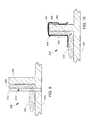
- FIG. 2 illustrates a first filter element 200 .
- the filter element 200 comprises a flow-through element 202 that filters a recirculation flow 204 in a sealed electromechanical assembly (such as the disc drive 100 in FIG. 1 ).
- the flow-through element 202 comprises an inlet surface 220 for receiving the flow 204 , that is contaminated with particles, and an opposite outlet surface 222 that expels the flow 204 .
- the outlet surface comprises a surface area that comprises at least 1.3 square centimeters.
- the flow-through element 202 comprises a lower rim 224 .
- the lower rim 224 has a tapered or rounded shape.
- the filter element 200 comprises a floor element 206 .
- the floor element 206 rests on a base (such as base 102 in FIG. 1 ) which inhibits air flow through the floor element.
- the floor element 206 has a perpendicular-facing major surface 208 that is perpendicular to the flow-through element.
- the floor element 206 comprises a proximal rim 226 .
- the proximal rim 226 has a tapered or rounded shape.
- the lower rim 224 is adjacent the proximal rim 226 .
- the lower rim 224 and the proximal rim 226 abut one another to form a crevice 212 (described in more detail below in connection with FIG. 3 ).
- the crevice 212 permanently traps a first portion of particles that become dislodged from the inlet surface 220 .
- the major surface 208 is disposed adjacent the flow-through element 202 .
- the major surface 208 comprises a particle trapping surface that traps a second portion of particles that become dislodged from the inlet surface 220 .
- the filter element 200 has a uniform cross-section along a body length 230 of the filter element 200 .
- the filter element 200 comprises a porous fabric of electrostatic fibers or other known filter media used in disc drives.
- the filter element 200 comprises a non-woven fabric. A region 210 of the filter element 200 is described in more detail below in connection with an enlarged drawing in FIG. 3 .
- the flow-through element 202 and the floor element 206 abut to form a first crevice 212 along a crevice length 214 between the flow-through element 202 and the floor element 206 .
- the first crevice 212 is formed by curved or taper portions of the flow-through element 202 and the floor element 206 .
- the first crevice 212 traps a first portion of the particles (such as particle 216 ) that become dislodged from the flow-through element 202 .
- the flow-through element 202 and the floor element 206 are formed of a single piece of fabric that has a fold that forms the first crevice 212 .
- an addition floor element 309 can be used adjacent an outlet surface 222 .
- FIGS. 4-5 illustrate a filter element 300 that is similar to the filter element 200 shown in FIGS. 2-3 , except that the filter element 300 includes a second floor element 308 that is positioned adjacent an outlet side 222 of the flow-through element 202 , and the floor elements 206 and 309 are separate components from the flow-through element 202 .
- Reference numbers used in FIGS. 4-5 that are the same as reference numbers used in FIGS. 2-3 identify the same or similar features and elements.
- the filter element 300 includes a crevice 212 adjacent an inlet surface 220 , and includes a crevice 313 adjacent an outlet surface 222 .
- the abutting surfaces of floor elements 206 , 309 are attached to surfaces of the flow-through element 202 by non-outgassing adhesive or other attachment method.
- FIG. 6 illustrates a filter element 350 that is similar to the filter element 200 shown in FIGS. 2-3 , except that the filter element 350 includes an additional crevice 352 in a floor element 354 .
- Reference numbers used in FIG. 6 that are the same as reference numbers used in FIGS. 2-3 identify the same or similar features and elements.
- the additional crevice 352 is formed, as illustrated, by providing a fold along a distal edge 356 of the floor element 354 .
- the additional crevice 352 is a crevice which permanently traps particles.
- FIG. 7 illustrates a filter element 370 that comprises multiple smaller filter elements 372 , 374 , 376 .
- Each of the multiple smaller filter elements 372 , 374 , 376 comprises a filter element such as filter element 200 shown in FIGS. 2-3 .
- the filter element 370 provides an increased total crevice length to enhance permanent particle capture capability.
- a floor element of filter element 372 functions as a ceiling element for filter element 374
- a floor element of filter element 374 functions as a ceiling element for filter element 376 .
- the availability of both floor and ceiling element functions permits mounting upside down without losing particle trapping capabilities of the crevices.
- FIG. 8 illustrates a filter element 380 that comprises multiple smaller filter elements 382 , 384 , 386 .
- Each of the multiple smaller filter elements 382 , 384 , 386 comprises a filter element such as filter element 300 shown in FIGS. 4-5 .
- the filter element 370 provides an increased total crevice length to enhance permanent particle capture capability on both inlet and outlet sides of the flow-through elements.
- a floor element of filter element 382 functions as a ceiling element for filter element 384
- a floor element of filter element 384 functions as a ceiling element for filter element 386 .
- the availability of both floor and ceiling element functions permits mounting upside down without losing particle trapping capabilities of the crevices.
- FIG. 9 illustrates a filter element 402 (such as filter element 200 in FIG. 2 ) that comprises a floor element 404 and a flow-through element 406 .
- the filter element 402 is mounted to a mounting wall 408 (such as mounting walls 134 , 136 in FIG. 1 ).
- the mounting wall 408 is a part of a base 410 (such as base 102 in FIG. 1 ).
- a pin 412 retains the flow-through element 406 in place by compression of a portion of the flow-through element 406 between the pin 412 and the mounting wall 408 .
- the flow-through element 406 is first compressed toward the mounting wall 408 using a tool, and then the pin 412 is inserted in the base 410 as illustrated, forming a puncture hole through the floor element 404 .
- the tool is removed, and the pin 412 functions as a compression component that mounts a mounting edge 414 to the mounting wall 408 .
- Multiple pins can be used to mount multiple mounting edges to multiple mounting walls as shown in FIG. 1 .
- non-outgassing adhesives can be used in addition to mounting pins to secure the filter element to walls in a disc drive.
- FIG. 10 illustrates a filter element 432 (such as filter element 200 in FIG. 2 ) that comprises a floor element 434 and a flow-through element 436 .
- the filter element 432 is mounted to a mounting wall 438 (such as mounting walls 134 , 136 in FIG. 1 ).
- the mounting wall 438 is a part of a base 440 (such as base 102 in FIG. 1 ).
- a spring wire clip 442 retains the flow-through element 436 in place by compression of a portion of the flow-through element 436 between the spring wire clip 442 and the mounting wall 438 .
- the flow-through element 436 is first compressed toward the mounting wall 438 using a tool, and the spring wire clip 442 is inserted in a slot 450 in the base 440 as illustrated, compressing the floor element 434 .
- the tool is removed, and the spring wire clip 442 functions as a compression component that mounts a mounting edge 444 to the mounting wall 438 .
- Multiple spring wire clips can be used to mount multiple mounting edges which are shown in FIG. 1 .
- non-outgassing adhesive can be used to secure the spring wire clip in the slot 450 .
- a similarly shaped sheet metal spring clip can also be used to provide the compression.
- FIG. 11 illustrates a plot of measured particle deposits (such as particles 502 , 504 ) on a disc 500 after completion of a functional doping test in a disc drive in which a filter element is provided with a flow-through element, but is not provided with a crevice between a floor element and flow-through element.
- a filter element is provided with a flow-through element, but is not provided with a crevice between a floor element and flow-through element.
- there are a large number of particles deposited particularly near a peripheral rim 506 .
- FIG. 12 illustrates a plot of measured particle deposits (such as particles 522 , 524 ) on a disc 520 after completion of a functional doping test in a disc drive in which a filter element is provided with a crevice between a floor element and flow-through element.
- a filter element is provided with a crevice between a floor element and flow-through element.
- FIG. 12 illustrates a small number of particles deposited.
- FIG. 11 and 12 it can be seen that the use of a filter element that includes a crevice between a flow-through element and floor element greatly reduces the number of particles on a disc in disc drive.
- FIG. 13 illustrates a bar graph of measured data errors in sample disc drives of a first type (type 1) after completion of a functional doping test.
- a filter element is provided that does not have a crevice between a floor element and flow-through element.
- sample drives I, J, K, L a filter element is provided that has a crevice between a floor element and flow-through element.
- the use of a filter element that includes a crevice between a flow-through element and floor element greatly reduces the number of measured data errors in the type 1 disc drive.
- FIG. 14 illustrates a bar graph of measured data errors in sample disc drives of a second type (type 2) after completion of a functional doping test.
- a filter element is provided that does not have a crevice between a floor element and flow-through element.
- sample drives 13 - 17 a filter element is provided that has a crevice between a floor element and flow-through element.
- the use of a filter element that includes a crevice between a flow-through element and floor element greatly reduces the number of measured data errors in the type 2 disc drive.
Abstract
Description
Claims (20)
Priority Applications (1)
| Application Number | Priority Date | Filing Date | Title |
|---|---|---|---|
| US12/581,545 US8123830B2 (en) | 2009-10-19 | 2009-10-19 | Filter element with particle-trapping crevice |
Applications Claiming Priority (1)
| Application Number | Priority Date | Filing Date | Title |
|---|---|---|---|
| US12/581,545 US8123830B2 (en) | 2009-10-19 | 2009-10-19 | Filter element with particle-trapping crevice |
Publications (2)
| Publication Number | Publication Date |
|---|---|
| US20110089038A1 US20110089038A1 (en) | 2011-04-21 |
| US8123830B2 true US8123830B2 (en) | 2012-02-28 |
Family
ID=43878463
Family Applications (1)
| Application Number | Title | Priority Date | Filing Date |
|---|---|---|---|
| US12/581,545 Expired - Fee Related US8123830B2 (en) | 2009-10-19 | 2009-10-19 | Filter element with particle-trapping crevice |
Country Status (1)
| Country | Link |
|---|---|
| US (1) | US8123830B2 (en) |
Cited By (1)
| Publication number | Priority date | Publication date | Assignee | Title |
|---|---|---|---|---|
| US9230608B2 (en) | 2013-06-20 | 2016-01-05 | Seagate Technology Llc | Filter element for disc drive enclosure |
Families Citing this family (1)
| Publication number | Priority date | Publication date | Assignee | Title |
|---|---|---|---|---|
| US10293293B2 (en) * | 2015-08-05 | 2019-05-21 | Donaldson Company, Inc. | Recirculation filter for an electronics enclosure |
Citations (12)
| Publication number | Priority date | Publication date | Assignee | Title |
|---|---|---|---|---|
| US4410341A (en) * | 1982-09-27 | 1983-10-18 | Magnetic Peripherals Inc. | Fluid filter cartridge |
| US20010017744A1 (en) | 2000-02-24 | 2001-08-30 | Bae Byoung-Young | Filtering apparatus for hard disk drive |
| US20030218829A1 (en) | 2002-05-23 | 2003-11-27 | Seagate Technology Llc | Fluid-borne contaminant protection using a filter assembly with a leading edge guide surface |
| US20040212920A1 (en) | 2002-10-07 | 2004-10-28 | Srinivas Tadepalli | Method of removing particles from an airflow and a data storage system including the same |
| US6999273B2 (en) | 2002-02-13 | 2006-02-14 | Seagate Technology Llc | Filter assembly for a data storage device |
| US7110215B2 (en) | 2002-06-13 | 2006-09-19 | Seagate Technology Llc | Breather filter at down-stream of re-circulation filter |
| US20070056444A1 (en) | 2005-07-12 | 2007-03-15 | Garikipati Vijay K | Electronic Enclosure Filter Containing Fluted Media |
| US20070283809A1 (en) | 2006-06-07 | 2007-12-13 | Boulay Daniel A | Recirculation filter |
| US20080047437A1 (en) | 2006-08-24 | 2008-02-28 | Seagate Technology Llc | Small and Large Particle Recirculation Filter |
| US20090015964A1 (en) | 2007-07-11 | 2009-01-15 | Seagate Technology Llc | Internal disc drive filter assembly |
| US20090073607A1 (en) | 2007-09-19 | 2009-03-19 | Seagate Technology Llc | Reduction in Particle Rebound Off of Component Surfaces |
| US20090183475A1 (en) | 2008-01-22 | 2009-07-23 | Dauber Edwin G | Pleated recirculation filter |
-
2009
- 2009-10-19 US US12/581,545 patent/US8123830B2/en not_active Expired - Fee Related
Patent Citations (13)
| Publication number | Priority date | Publication date | Assignee | Title |
|---|---|---|---|---|
| US4410341A (en) * | 1982-09-27 | 1983-10-18 | Magnetic Peripherals Inc. | Fluid filter cartridge |
| US20010017744A1 (en) | 2000-02-24 | 2001-08-30 | Bae Byoung-Young | Filtering apparatus for hard disk drive |
| US6473264B2 (en) * | 2000-02-24 | 2002-10-29 | Samsung Electronics Co., Ltd. | Filtering apparatus for hard disk drive |
| US6999273B2 (en) | 2002-02-13 | 2006-02-14 | Seagate Technology Llc | Filter assembly for a data storage device |
| US20030218829A1 (en) | 2002-05-23 | 2003-11-27 | Seagate Technology Llc | Fluid-borne contaminant protection using a filter assembly with a leading edge guide surface |
| US7110215B2 (en) | 2002-06-13 | 2006-09-19 | Seagate Technology Llc | Breather filter at down-stream of re-circulation filter |
| US20040212920A1 (en) | 2002-10-07 | 2004-10-28 | Srinivas Tadepalli | Method of removing particles from an airflow and a data storage system including the same |
| US20070056444A1 (en) | 2005-07-12 | 2007-03-15 | Garikipati Vijay K | Electronic Enclosure Filter Containing Fluted Media |
| US20070283809A1 (en) | 2006-06-07 | 2007-12-13 | Boulay Daniel A | Recirculation filter |
| US20080047437A1 (en) | 2006-08-24 | 2008-02-28 | Seagate Technology Llc | Small and Large Particle Recirculation Filter |
| US20090015964A1 (en) | 2007-07-11 | 2009-01-15 | Seagate Technology Llc | Internal disc drive filter assembly |
| US20090073607A1 (en) | 2007-09-19 | 2009-03-19 | Seagate Technology Llc | Reduction in Particle Rebound Off of Component Surfaces |
| US20090183475A1 (en) | 2008-01-22 | 2009-07-23 | Dauber Edwin G | Pleated recirculation filter |
Cited By (1)
| Publication number | Priority date | Publication date | Assignee | Title |
|---|---|---|---|---|
| US9230608B2 (en) | 2013-06-20 | 2016-01-05 | Seagate Technology Llc | Filter element for disc drive enclosure |
Also Published As
| Publication number | Publication date |
|---|---|
| US20110089038A1 (en) | 2011-04-21 |
Similar Documents
| Publication | Publication Date | Title |
|---|---|---|
| US6395073B1 (en) | Multi-functional filter for removing contaminants from an enclosure | |
| US6296691B1 (en) | Multi-functional molded filter for removing contaminants from an enclosure | |
| JP5201682B2 (en) | Low fiber disc / shroud filter structure for removing contaminants from a housing | |
| US7312950B2 (en) | Air stream filtration system adjacent a rotational element of a data storage device | |
| US20090183475A1 (en) | Pleated recirculation filter | |
| US7601192B2 (en) | Recirculation filter | |
| US8123830B2 (en) | Filter element with particle-trapping crevice | |
| US20030156352A1 (en) | Multiple filter for use in a disc drive | |
| US20070256396A1 (en) | Integrated filter assembly | |
| US7585358B2 (en) | Small and large particle recirculation filter | |
| US7597012B2 (en) | System and method for using a spray/liquid particle count (LPC) to measure particulate contamination | |
| US20030156351A1 (en) | Multiple filter for use in a disc drive | |
| US7667924B2 (en) | Particle extracting device of hard disk drive and hard disk drive including the same | |
| US7697223B2 (en) | Monitoring a fly height of a magnetic transducer | |
| US20090073607A1 (en) | Reduction in Particle Rebound Off of Component Surfaces | |
| US7298571B1 (en) | Method and a system for maintaining an acceptable level of relative humidity inside of a disk drive | |
| WO2007005084A2 (en) | Improved filter construction for removing contaminants from an enclosure | |
| WO2010036351A1 (en) | Improved filter construction for removing contaminants from an enclosure | |
| JPH03216887A (en) | Magnetic disk device | |
| JP2753886B2 (en) | Method of manufacturing magnetic disk drive | |
| EP0053191A1 (en) | Cleaning device for tape recorder head | |
| WO2007004255A1 (en) | Information storing device | |
| JP2007073106A (en) | Monitoring method of manufacture environment of magnetic disk drive and manufacturing method of magnetic disk drive | |
| KR20090012926U (en) | Device for cleaning a spindle support flange of device for reading and/or recording information to and form compact disks | |
| JPS63157389A (en) | Magnetic disk device |
Legal Events
| Date | Code | Title | Description |
|---|---|---|---|
| AS | Assignment |
Owner name: SEAGATE TECHNOLOGY LLC, CALIFORNIA Free format text: ASSIGNMENT OF ASSIGNORS INTEREST;ASSIGNORS:CAMALIG, CLIFFORD JAYSON BRINGAS;BUANG, ASMIN;REEL/FRAME:023399/0690 Effective date: 20091013 |
|
| AS | Assignment |
Owner name: THE BANK OF NOVA SCOTIA, AS ADMINISTRATIVE AGENT, Free format text: SECURITY AGREEMENT;ASSIGNOR:SEAGATE TECHNOLOGY LLC;REEL/FRAME:026010/0350 Effective date: 20110118 |
|
| ZAAA | Notice of allowance and fees due |
Free format text: ORIGINAL CODE: NOA |
|
| ZAAB | Notice of allowance mailed |
Free format text: ORIGINAL CODE: MN/=. |
|
| STCF | Information on status: patent grant |
Free format text: PATENTED CASE |
|
| AS | Assignment |
Owner name: THE BANK OF NOVA SCOTIA, AS ADMINISTRATIVE AGENT, CANADA Free format text: SECURITY AGREEMENT;ASSIGNORS:SEAGATE TECHNOLOGY LLC;EVAULT, INC. (F/K/A I365 INC.);SEAGATE TECHNOLOGY US HOLDINGS, INC.;REEL/FRAME:029127/0527 Effective date: 20120718 Owner name: WELLS FARGO BANK, NATIONAL ASSOCIATION, AS COLLATERAL AGENT, CALIFORNIA Free format text: SECOND LIEN PATENT SECURITY AGREEMENT;ASSIGNORS:SEAGATE TECHNOLOGY LLC;EVAULT, INC. (F/K/A I365 INC.);SEAGATE TECHNOLOGY US HOLDINGS, INC.;REEL/FRAME:029253/0585 Effective date: 20120718 Owner name: THE BANK OF NOVA SCOTIA, AS ADMINISTRATIVE AGENT, Free format text: SECURITY AGREEMENT;ASSIGNORS:SEAGATE TECHNOLOGY LLC;EVAULT, INC. (F/K/A I365 INC.);SEAGATE TECHNOLOGY US HOLDINGS, INC.;REEL/FRAME:029127/0527 Effective date: 20120718 Owner name: WELLS FARGO BANK, NATIONAL ASSOCIATION, AS COLLATE Free format text: SECOND LIEN PATENT SECURITY AGREEMENT;ASSIGNORS:SEAGATE TECHNOLOGY LLC;EVAULT, INC. (F/K/A I365 INC.);SEAGATE TECHNOLOGY US HOLDINGS, INC.;REEL/FRAME:029253/0585 Effective date: 20120718 |
|
| FEPP | Fee payment procedure |
Free format text: PAYOR NUMBER ASSIGNED (ORIGINAL EVENT CODE: ASPN); ENTITY STATUS OF PATENT OWNER: LARGE ENTITY |
|
| FPAY | Fee payment |
Year of fee payment: 4 |
|
| MAFP | Maintenance fee payment |
Free format text: PAYMENT OF MAINTENANCE FEE, 8TH YEAR, LARGE ENTITY (ORIGINAL EVENT CODE: M1552); ENTITY STATUS OF PATENT OWNER: LARGE ENTITY Year of fee payment: 8 |
|
| FEPP | Fee payment procedure |
Free format text: MAINTENANCE FEE REMINDER MAILED (ORIGINAL EVENT CODE: REM.); ENTITY STATUS OF PATENT OWNER: LARGE ENTITY |
|
| LAPS | Lapse for failure to pay maintenance fees |
Free format text: PATENT EXPIRED FOR FAILURE TO PAY MAINTENANCE FEES (ORIGINAL EVENT CODE: EXP.); ENTITY STATUS OF PATENT OWNER: LARGE ENTITY |
|
| STCH | Information on status: patent discontinuation |
Free format text: PATENT EXPIRED DUE TO NONPAYMENT OF MAINTENANCE FEES UNDER 37 CFR 1.362 |