US8112373B2 - Nerve equivalent circuit, synapse equivalent circuit and nerve cell body equivalent circuit - Google Patents
Nerve equivalent circuit, synapse equivalent circuit and nerve cell body equivalent circuit Download PDFInfo
- Publication number
- US8112373B2 US8112373B2 US12/281,812 US28181207A US8112373B2 US 8112373 B2 US8112373 B2 US 8112373B2 US 28181207 A US28181207 A US 28181207A US 8112373 B2 US8112373 B2 US 8112373B2
- Authority
- US
- United States
- Prior art keywords
- equivalent circuit
- nerve cell
- synapses
- constant
- synapse
- Prior art date
- Legal status (The legal status is an assumption and is not a legal conclusion. Google has not performed a legal analysis and makes no representation as to the accuracy of the status listed.)
- Active, expires
Links
Images


Classifications
-
- G—PHYSICS
- G06—COMPUTING OR CALCULATING; COUNTING
- G06N—COMPUTING ARRANGEMENTS BASED ON SPECIFIC COMPUTATIONAL MODELS
- G06N3/00—Computing arrangements based on biological models
- G06N3/02—Neural networks
- G06N3/06—Physical realisation, i.e. hardware implementation of neural networks, neurons or parts of neurons
- G06N3/063—Physical realisation, i.e. hardware implementation of neural networks, neurons or parts of neurons using electronic means
- G06N3/065—Analogue means
Definitions
- This invention relates to a nerve equivalent circuit, a synapse equivalent circuit and a nerve cell body equivalent circuit. More particularly, the present invention relates to a nerve equivalent circuit, a synapse equivalent circuit and a nerve cell body equivalent circuit that simulate respectively the electric characteristics of the nerve circuits, those of the synapses and those of the nerve cell bodies.
- the signal transmission among nerve cells is known to be realized by electric signals that resemble an impulse train corresponding to pulse frequency modulation.
- the Hodgkin Huxley equations for describing the ignition mechanism of nerve cells are also well known.
- the nerve cell membrane can be expressed by an electric equivalent circuit of a certain type and the nerve activity can be expressed by expressing the conductance relative to ions by means of a function of voltage and time.
- Patent Document 1 an artificial nerve circuit shown in Patent Document 1 is known as an equivalent circuit simulating the ignition phenomenon.
- Patent Document 1 Japanese Patent Application Kokai Publication No. Hei 07-168901
- Non-Patent Document 1 D. E. Rumelhart, G. E. Hinton & R. J. Williams, “Learning Internal Representations by Back-Propagation Errors”, Nature, 323, 533-536, Oct. (1986)
- Patent Document 1 while a pulse is output from the axon circuit when the output potential of the nerve cell body circuit exceeds a predetermined threshold value, the circuit cannot be provided with an arithmetic function like that of nerve cells unlike the physiological characteristics of actual nerve cells because the electric potential of the nerve cell body circuit never falls. Further, the axon circuit according to Patent Document 1 is merely a channel for correctly transmitting information, not provided with an arithmetic function.
- the sigmoid function is mainly employed in each unit of neural networks that have been proposed to date, they are not dynamic systems. Therefore, it is difficult for them to control the object to be controlled that is a dynamic system. Additionally, the neural networks that have been proposed to date are algorithms obtained on the basis of mathematical ideas and do not involve the use of the characteristics of actual nerves.
- an object of the present invention is to mathematize input/output relations of a nerve circuit, a synapse and a nerve cell body and provide a nerve equivalent circuit, a synapse equivalent circuit and a nerve cell body equivalent circuit where the electric characteristics that are in accordance with the physiological characteristics and the physical structures of nerve cells are faithfully reproduced.
- the above object is achieved by providing a synapse equivalent circuit for simulating electric characteristics of synapses, the circuit comprising an input terminal and an output terminal, an input signal f in (t) input to the input terminal and an output signal I psp (t) output from the output terminal having the relationship expressed by the formula shown below:
- k P is a constant within a range defined by ⁇ k P ⁇
- k I is a constant within the range defined by ⁇ k I ⁇
- T I is a constant within the range defined by 0 ⁇ T I ⁇
- e is the Napier's constant
- t time
- the input terminal may be connected to a voltage control resistance section through an electric resistance and the output terminal is connected to the voltage control resistance section through a power source in order to realize the first term of the right side of the above formula.
- an electric potential between the electric resistance and the voltage control resistance section may be connected to a reference potential through a parallel circuit where a second electric resistance and a capacitor are connected in parallel in order to realize the second term of the right side of the above formula.
- the parallel circuit may further have a coil connected in parallel.
- the input terminal may be connected to an environment sensory section.
- the input signal f in (t) may be input to the input terminal through a signal rectification device.
- a nerve cell body equivalent circuit for simulating electric characteristics of nerve cell bodies, the circuit comprising an input terminal and an output terminal, an input signal I psp (t) input to the input terminal and a membrane potential V m (t) output from the output terminal having the relationship expressed by the formula shown below:
- E 0 is a resting membrane potential
- k m is a constant within the range defined by 0 ⁇ k m ⁇
- T m is a constant within the range defined by 0 ⁇ T m ⁇
- e is the Napier's constant
- t time
- t 0 is the time when the preceding pulse ended
- ⁇ is the threshold value of an active potential of nerve cell membrane
- ⁇ (t) is an impulse function.
- a nerve cell body equivalent circuit may be constituted by connecting, in parallel between the output terminal and a reference potential terminal, a circuit where a capacitor corresponding to the cell membrane capacitance, a circuit where a power source corresponding to the resting membrane potential and an electric resistance corresponding to a permeability of cell membrane are connected in series, and a sodium ion channel equivalent circuit which connects in series a power source corresponding to an equivalent potential of a chemical potential of a sodium ion, a relay element corresponding to a sodium ion channel, and an electric resistance corresponding to a permeability of a sodium ion channel.
- a nerve cell body equivalent circuit may be constituted by further connecting, in parallel between the output terminal and the reference potential terminal, a potassium ion channel equivalent circuit which connects in series a power source corresponding to the equivalent potential of a chemical potential of a potassium ion, a relay element corresponding to a potassium ion channel, and an electric resistance corresponding to a permeability of the potassium ion channel.
- a nerve cell body equivalent circuit may be constituted by further connecting, in parallel between the output terminal and the reference potential terminal, an ion channel equivalent circuit which connects in series a power source corresponding to the equivalent potential of the chemical potential of a predetermined ion other than a sodium ion and a potassium ion, a relay element corresponding to the ion channel of the predetermined ion, and an electric resistance corresponding to a permeability of the ion channel of the predetermined ion.
- the output terminal may be connected to an object to be controlled by the nerve cell body equivalent circuit.
- a nerve equivalent circuit for simulating the electric characteristics of a nerve cell, in which an input signal f in (t) and an output signal f out (t) thereof have a relationship expressed by the formula shown below:
- k P is a constant within a range defined by ⁇ k P ⁇
- k I is a constant within the range defined by ⁇ k I ⁇
- T I is a constant within the range defined by 0 ⁇ T I ⁇
- e is the Napier's constant
- t is time
- the output terminal of a synapse equivalent circuit may be connected to the input terminal of a nerve cell body equivalent circuit.
- the input terminal of a synapse equivalent circuit may be connected to the output terminal of a nerve cell body equivalent circuit.
- a program for causing a computer to function as a synapse equivalent circuit a program for causing a computer to function as a nerve cell body equivalent circuit, and a program for causing a computer to function as a nerve equivalent circuit.
- a nerve equivalent circuit, a synapse equivalent circuit and a nerve cell body equivalent circuit according to the present invention have an advantage that they can faithfully reproduce the electric characteristics in accordance with the physiological functions and the physical structures of nerve cells. Additionally, a nerve equivalent circuit, a synapse equivalent circuit and a nerve cell body equivalent circuit according to the present invention can process information and transmit signals on a stable basis. Still additionally, since the input/output relationships of a nerve equivalent circuit, a synapse equivalent circuit and a nerve cell body equivalent circuit are anathematized, the functions of a nerve equivalent circuit, a synapse equivalent circuit and a nerve cell body equivalent circuit according to the present invention can be realized not only by means of electric circuits but also on a computer.
- a nerve cell body equivalent circuit according to the present invention is designed to improve the equivalent circuit formed by using the Hodgkin Huxley equations and realize the function of an ion channel by means of an electric element and other elements.
- the present invention also proposes a synapse equivalent circuit that can realize an excitatory synapse and an inhibitory synapse that are most important for inputting and processing signals and also provides a nerve equivalent circuit realizing an equivalent circuit of an entire nerve cell.
- an equivalent circuit of a synapse that is a structure at a site of junction relating to nerve activities formed among nerve cells can be realized and signals can be input to and output from there. Therefore, a nerve equivalent circuit that processes signals on a principle same as a nerve cell can be realized.
- a nerve equivalent circuit where the signal from the environment sensory sensor is input to the synapse equivalent circuit just like the signal from a perception cell is transmitted to a nerve cell and the output thereof is transmitted to a nerve cell body equivalent circuit can be realized.
- a nerve cell body equivalent circuit can be connected to a section to be controlled such as a motor or an actuator to be controlled by a nerve cell body equivalent circuit or a driver circuit for controlling such a motor or an actuator, a nerve equivalent circuit where the signal from a nerve cell body equivalent circuit is transmitted to the section to be controlled just like the signal from a nerve cell is transmitted to a muscle cell can be realized.
- I psp (t) is the electric current flowing from the post-synapse to the nerve cell body
- V m (t) is the membrane potential
- ⁇ E 0 is the resting membrane potential
- N is the total number of synapses
- n 1, 2, . . . , N and represents the ordinal number of a synapse connected to the nerve cell
- t is time
- C m is the electric capacitance of the cell membrane
- g o is the equivalent conductance of the cell membrane relative to the entire permeable ions.
- V m (O) is the membrane potential after the end of an action potential
- e is the Napier's constant
- t 0 is the time when the preceding pulse ended
- C m is the electric capacitance of the cell membrane.
- k m is a constant within the range defined by 0 ⁇ k m ⁇
- T m is a constant within the range defined by 0 ⁇ T m ⁇
- ⁇ is the threshold value of the active potential of nerve cell membrane
- ⁇ (t) is an impulse function
- Any circuit having an input/output relationship that satisfies the above formula can be said to be an equivalent circuit that simulates a nerve cell body.
- an impulse function ⁇ (t) can be approximately realized typically by means of a relay circuit.
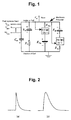
- FIG. 1 is a schematic conceptual circuit diagram of a nerve cell body equivalent circuit according to the present invention.
- the capacitor C m corresponds to the electric capacitance of the cell membrane and the potential difference of the capacitor C m corresponds to the membrane potential of the cell membrane.
- E o corresponds to a power source that corresponds to the resting membrane potential and takes the role of an ion pump or an impermeable negative ion. Additionally, E Na and E K in FIG.
- Relay element (Na + ) is an element for realizing the electric characteristics of the ion channel of Na + , which element is tuned on when the membrane potential V m exceeds a predetermined threshold value.
- Relay element (K + ) is an element for realizing the electric characteristics of the ion channels of K + , which element is tuned on when the membrane potential V m exceeds a predetermined threshold value. There may be a plurality of current inputs from the post-synapse and they are expressed by 1 I psp through M I psp .
- the Na + channel is formed by connecting a power source E Na , a relay element (Na + ) and an electric resistance g Na in series between the output terminal where the membrane potential V m is obtained and the reference potential terminal that is grounded.
- the K + channel is formed by connecting a power source E K , a relay element (K + ) and an electric resistance gK in series between the output terminal where the membrane potential V m is obtained and the reference potential terminal that is grounded.
- a circuit formed by connecting a capacitor C m , a power source E o and an electric resistance g o in series is connected in parallel with equivalent circuit of the Na + channel and that of the K + channel. With this arrangement, a nerve cell body equivalent circuit is reproduced in principle.
- the relay element (Na + ) When the membrane potential V m exceeds a predetermined threshold value, the relay element (Na + ) is turned on and an electric current flows into the Na + channel from the power source E Na , so that the membrane potential V m rapidly rises. At the same time, the relay element (K + ) is turned on and the electric charge of the capacitor C m flows out into the K + channel, so that the membrane potential V m rapidly falls. In this way, the illustrated nerve cell body equivalent circuit reproduces the ignition characteristic of a nerve cell body.
- an equivalent circuit such as a Ca + channel of calcium ion formed by connecting a power source corresponding to the equivalent potential of the chemical potential of a predetermined ion other than a sodium ion and a potassium ion, a relay element corresponding to the ion channel of the predetermined ion and an electric resistance corresponding to a permeability of the ion channel of the predetermined ion are connected in series may further be connected in parallel with the equivalent circuit of the Na + channel and that of the K + channel.
- the inter-nerve cell signal transmission is realized by the pre-synapse and the post-synapse.
- a predetermined quantity of transmitter substances is discharged into the synaptic cleft from the synaptic vesicle and the ion channels that correspond to the respective transmitter substances located at the post-synapse open.
- ions that correspond to the opened channels flow through the channels.
- an excitatory synapse the electric potential of the cell membrane rises to give rise to depolarization.
- an inhibitory synapse the electric potential of the cell membrane falls to give rise to hyperpolarization.
- the time T c at which the channel opens and the type of channel that opens varies from channel to channel depending on the transmitter substance.
- Two types of waveforms as shown in FIG. 2 exist as waveforms of the post-synaptic potential from an excitatory synapse that is produced by a pulse.
- the waveform of (a) in FIG. 2 is close to the first order lag waveform expressed by the formula shown below:
- k is a constant within the range defined by 0 ⁇ k ⁇
- T is a constant within the range defined by 0 ⁇ T ⁇ .
- T 1 and T 2 are constant within the ranges defined by 0 ⁇ T 1 ⁇ and 0 ⁇ T 2 ⁇ respectively.
- V m ⁇ ( t ) - E 0 + 1 C m ⁇ e - g 0 C m ⁇ t It will be seen that this also corresponds to the waveform of first order lag of (a) in FIG. 2 .
- V m ⁇ ( t ) - E 0 + kT g 0 ⁇ T - C m ⁇ ( e - 1 T ⁇ t - e - g 0 C m ⁇ t ) It will be seen that the formula shown above corresponds to the waveform of (b) in FIG. 2 .
- g s (t) is the time domain form of G s (s) and hence is an impulse response.
- I psp ⁇ ( t ) k P ⁇ f i ⁇ ⁇ n ⁇ ⁇ ( t ) [ Formula ⁇ ⁇ 6 ]
- I psp ⁇ ( t ) k I ⁇ ⁇ 0 t ⁇ e - 1 T I ⁇ ( t - ⁇ ) ⁇ f i ⁇ ⁇ n ⁇ ( ⁇ ) ⁇ d ⁇ [ Formula ⁇ ⁇ 7 ]
- k P is a constant within the range defined by ⁇ k P ⁇
- k I is a constant within the range defined by ⁇ k I ⁇
- T I is a constant within the range defined by 0 ⁇ T I ⁇ .
- the input signal f in (t) and the output signal I psp (t) of the synapse equivalent circuit have a relationship as defined below:
- FIG. 3 (a) is a schematic conceptual circuit diagram of a synapse equivalent circuit according to the present invention.
- V P (t) is the external input voltage
- V B (t) is the control voltage of the voltage control resistance section
- E i is the equivalent potential of the chemical potential of the corresponding ion and electric resistor g n , electric resistor g c and capacitor C c form an RC circuit element for realizing the characteristic of a second transmitter substance of Formula 8.
- VCR voltage control resistance section
- the input terminal of the synapse equivalent circuit is connected to the control terminal of the voltage control resistance section through electric resistor g n and the output terminal of the synapse equivalent circuit is connected to the voltage control resistance section through power source E i .
- the electric potential between the electric resistor g n and the control terminal of the voltage control resistance section is connected to a reference potential through a parallel circuit where the electric resistor g c and the capacitor C c are connected in parallel.
- the parallel circuit corresponds to the second transmitter substance. When this parallel circuit is not employed, it corresponds to a synapse having only the first transmitter substance.
- the input/output relationship of the nerve equivalent circuit can be made to be of the second order by connecting a coil or the like in parallel with the parallel circuit.
- V B ⁇ ( t ) V B ⁇ ( 0 ) ⁇ e - g C + g n C C ⁇ V B ⁇ ( t ) + g n C C ⁇ V P ⁇ ( t ) [ Formula ⁇ ⁇ 10 ]
- V B ⁇ ( t ) V B ⁇ ( 0 ) ⁇ e - g C + g n C C ⁇ t + 1 C C ⁇ ⁇ 0 t ⁇ e - g C + g n C C ⁇ ( ⁇ - t ) ⁇ ⁇ g n ⁇ V P ⁇ ( ⁇ ) ⁇ d ⁇
- V B ⁇ ( t ) d t - g C + g n C C ⁇ V B ⁇ ( t ) + q in C C ⁇ f in ⁇ ( t )
- V B ⁇ ( t ) V B ⁇ ( 0 ) ⁇ e - g C + g n C C ⁇ t + q in C C ⁇ ⁇ 0 t ⁇ e - g C + g n C C ⁇ ( ⁇ - t ) ⁇ ⁇ f in ⁇ ( ⁇ ) ⁇ d ⁇
- k T is a constant that is determined as a function of the type of the channel to be expressed and the type and the quantity of transmitter substance.
- I psp ⁇ ( s ) k T ⁇ V B ⁇ ( 0 ) ⁇ e - g C + g n C C ⁇ t + k T ⁇ q in C C ⁇ ⁇ 0 t ⁇ e - g C + g n C C ⁇ ( ⁇ - t ) ⁇ ⁇ f in ⁇ ( ⁇ ) ⁇ d ⁇
- the synapse equivalent circuit of FIG. 3 satisfies the input/output relationship of Formula 7.
- Various characteristics of synapse can be realized by adjusting the values of capacitance, resistance and so on of C c , g n , g c and k T that are parameters.
- Synapse equivalent circuits other than those shown in FIG. 3 are also conceivable.
- a synapse equivalent circuit according to the present invention is required only to realize the input/output relationship of Formula 6 or Formula 7. It is sufficient for a synapse equivalent circuit having a plurality of types of transmitter substance to realize the input/output relationship of Formula 8.
- the relationship can typically be realized by a circuit as shown in FIG. 4 .
- m g s (t) represents the circuit shown in FIG. 3 .
- FIG. 5 shows a more specific exemplary synapse equivalent circuit.
- FIG. 5 is a synapse equivalent circuit for realizing an excitatory synapse having the first transmitter substance.
- the circuit of FIG. 5 is an excitatory synapse equivalent circuit for realizing a transmitter substance that acts on channels of the same type ions. Note that the voltage of V 6 varies when the type of ions to be acted upon differs.
- FIG. 6 is a graph illustrating an exemplary input/output relationship of the synapse equivalent circuit of FIG. 5 , using a temporal axis. It will be seen that the membrane potential gradually rises as pulse trains are input from three synapses. Synapses having any of various different first transmitter substances can be realized by changing the resistance values (R 2 , R 7 , R 11 and R 4 , R 8 , R 9 , etc.)
- FIG. 7 is a specific exemplary synapse equivalent circuit diagram for realizing an inhibitory synapse having a first transmitter substance.
- the circuit of FIG. 7 is an inhibitory synapse equivalent circuit for realizing a transmitter substance that acts on channels of the same type ions. Note that the voltage of V 3 varies when the type of ions to be acted upon differs.
- FIG. 8 is a graph illustrating an exemplary input/output relationship of the synapse equivalent circuit of FIG. 7 , using a temporal axis. It will be seen that the membrane potential gradually falls as pulse trains are input from three synapses. Synapses having any of various different first transmitter substances can be realized by changing the resistance values (R 1 , R 2 , R 3 and R 19 , R 20 , R 21 , etc.).
- ⁇ n 1 N ⁇ I psp n ⁇ ( t )
- n I psp is the electric current that is made to flow out/in by the n-th synapse and N is the total number of synapses in the nerve cell body.
- the electric current that passes the membrane can be made equal to 0 because all the ions in the resting state are held in a state of equilibrium.
- the electric capacitance of the cell membrane is taken for a capacitor, repetition of ignition and rest of a cell can be considered as repetition of charge and discharge of a capacitor.
- the move of an electric charge can be regarded as 0.
- ⁇ n 1 N ⁇ I psp n ⁇ ( t ) - q P ⁇ f out ⁇ ( t ) ⁇ 0
- k P and k I include q p
- the input signal f in (t) and the output signal f out (t) of the nerve equivalent circuit has a relationship defined by the formula shown below.
- An entire nerve equivalent circuit as shown in FIG. 9 can be formed by integrally combining the above-described synapse equivalent circuits and nerve cell body equivalent circuits.
- a plurality of synapse equivalent circuits is connected to a nerve cell body equivalent circuit so as to operate as a plurality of excitatory synapses and a plurality of inhibitory synapses.
- an ordinary amplifier can be used for the VCR (voltage control resistance section) to realize similar characteristics.
- R esa and R isa indicate resistance values that are the functions of the distance from the synapse to the axon initial segment.
- FIG. 10 is a more specific exemplary circuit diagram of a nerve equivalent circuit according to the present invention.
- the circuit shown in FIG. 10 is formed by connecting a synapse equivalent circuit for realizing excitatory synapses and a nerve cell body equivalent circuit of Na + channel.
- the nerve equivalent circuit in FIG. 10 connects an excitatory synapse equivalent circuit having a first transmitter substance and a nerve cell body equivalent circuit of Na + channel, and
- FIG. 11 is a graph illustrating an exemplary input/output relationship thereof.
- FIG. 12 is a more specific exemplary circuit diagram of an entire nerve equivalent circuit according to the present invention that employs a K + channel in combination.
- the nerve equivalent circuit of FIG. 12 is formed by connecting an excitatory synapse equivalent circuit having a first transmitter substance, an inhibitory synapse equivalent circuit having a first transmitter substance and a nerve cell body equivalent circuit having a Na + channel and a K + channel.
- FIG. 13 is a graph illustrating an exemplary input/output relationship of the nerve equivalent circuit of FIG. 12 .
- FIG. 14 is another more specific exemplary circuit diagram of a nerve equivalent circuit of an entire nerve cell according to the present invention.
- the nerve equivalent circuit of FIG. 14 is formed by connecting an excitatory synapse equivalent circuit having a second transmitter substance and a nerve cell body equivalent circuit having a Na + channel and a K + channel.
- FIG. 15 is a graph illustrating an exemplary input/output relationship of the nerve equivalent circuit of FIG. 14 . As seen from FIG. 15 , the input/output relationship is an integration relationship having omissions.
- FIG. 16 is another more specific exemplary circuit diagram of a nerve equivalent circuit of an entire nerve cell according to the present invention.
- the nerve equivalent circuit of FIG. 16 is formed by connecting an excitatory synapse equivalent circuit having a first transmitter substance and a nerve cell body equivalent circuit having a Na + channel and a K + channel, and
- various nerve equivalent circuits can be realized by combining elements selected from first transmitter substances, second transmitter substances, excitatory synapses, inhibitory synapses, Na + channels and K + channels.
- While individual nerve equivalent circuits may exist by themselves alone, a plurality of such nerve equivalent circuits may be connected to each other to form a circuit as in the case of real nerve cells. More specifically, such a circuit may be formed by connecting the output terminal of a nerve cell body equivalent circuit to the input terminal of a synapse equivalent circuit and so on or by connecting the output terminals of a plurality of synapse equivalent circuits to the input terminal of a nerve cell body equivalent circuit, while connecting the output terminal of a nerve cell body equivalent circuit to the input terminals of a plurality of still other synapse equivalent circuits. Furthermore, signals from an environment sensory section including a temperature sensor and/or a pressure sensor that senses the external environment may be input to the synapse equivalent circuits. The output signal of the nerve cell body equivalent circuit may be used as a control signal for external objects to be controlled, namely actuators.
- the present invention is by no means limited thereto and the present invention can be embodied as a program that can be executed on a computer.
- a nerve equivalent circuit a synapse equivalent circuit and a nerve cell body equivalent circuit according to the present invention can be expressed by means of formulas, they can be embodied as programs with ease. Such programs can be realized very easily even when a large scale nerve circuit is simulated.
- a nerve equivalent circuit according to the present invention is by no means limited to the illustrated examples described above, which may be modified and altered in various different ways without departing from the spirit and scope of the present invention.
- pulses and analog signals can be used respectively as inputs to and outputs from a synapse equivalent circuit according to the present invention, it can be applied by itself to a converter or the like for converting a pulse frequency modulation signal to an analog signal.
- analog signals and pulse signals can be used respectively as inputs to and outputs from a nerve cell body equivalent circuit according to the present invention, it can be applied by itself to a converter or the like for converting an analog signal into a pulse frequency modulation signal.
- FIG. 1 is a schematic conceptual circuit diagram of a nerve cell body equivalent circuit according to the present invention.
- FIG. 2 is a schematic waveform of the post-synaptic potential from an excitatory synapse caused to take place by a pulse.
- FIG. 3 is a schematic conceptual circuit diagram of a synapse equivalent circuit according to the present invention.
- FIG. 4 is a schematic conceptual circuit diagram of a synapse equivalent circuit having a plurality of kinds of transmitter substances.
- FIG. 5 is a more specific exemplary circuit diagram for the synapse equivalent circuit shown in FIG. 3 .
- FIG. 6 is a graph illustrating an exemplary input/output relationship of the synapse equivalent circuit shown in FIG. 5 .
- FIG. 7 is a specific exemplary synapse equivalent circuit diagram for realizing an inhibitory synapse having a first transmitter substance.
- FIG. 8 is a graph illustrating an exemplary input/output relationship of the synapse equivalent circuit shown in FIG. 7 .
- FIG. 9 is a schematic conceptual circuit diagram of an entire nerve equivalent circuit according to the present invention.
- FIG. 10 is a more specific exemplary circuit diagram of a nerve equivalent circuit according to the present invention.
- FIG. 11 is a graph illustrating an exemplary input/output relationship of the nerve equivalent circuit shown in FIG. 10 .
- FIG. 12 is a more specific exemplary circuit diagram of an entire nerve equivalent circuit according to the present invention.
- FIG. 13 is a graph illustrating an exemplary input/output relationship of the nerve equivalent circuit shown in FIG. 12 .
- FIG. 14 is another more specific exemplary circuit diagram of an entire nerve equivalent circuit according to the present invention.
- FIG. 15 is a graph illustrating an exemplary input/output relationship of the nerve equivalent circuit shown in FIG. 14 .
- FIG. 16 is another more specific exemplary circuit diagram of an entire nerve equivalent circuit according to the present invention.
- FIG. 17 is a graph illustrating the relationship between the input signal and the membrane potential of the nerve cell body equivalent circuit shown in FIG. 16 .
Landscapes
- Engineering & Computer Science (AREA)
- Physics & Mathematics (AREA)
- Health & Medical Sciences (AREA)
- Life Sciences & Earth Sciences (AREA)
- Biomedical Technology (AREA)
- Biophysics (AREA)
- Theoretical Computer Science (AREA)
- Evolutionary Computation (AREA)
- General Engineering & Computer Science (AREA)
- Data Mining & Analysis (AREA)
- Artificial Intelligence (AREA)
- General Health & Medical Sciences (AREA)
- Molecular Biology (AREA)
- Computing Systems (AREA)
- Computational Linguistics (AREA)
- General Physics & Mathematics (AREA)
- Mathematical Physics (AREA)
- Software Systems (AREA)
- Neurology (AREA)
- Networks Using Active Elements (AREA)
- Electrotherapy Devices (AREA)
- Electronic Switches (AREA)
Abstract
Description
It will be seen that this also corresponds to the waveform of first order lag of (a) in
the membrane potential Vm(t) can be expressed by the formula shown below.
It will be seen that the formula shown above corresponds to the waveform of (b) in
I psp(s)=G s(s)F in(s) [Formula 3]
I psp(t)=∫0 t g s(τ−t)f in(τ)dτ
g n V P(t)=q in f in(t)
I psp(t)≈k T V B(t)
I out(t)=q pfout(t)
Claims (17)
Applications Claiming Priority (3)
| Application Number | Priority Date | Filing Date | Title |
|---|---|---|---|
| JP2006-060338 | 2006-03-06 | ||
| JP2006060338A JP4997495B2 (en) | 2006-03-06 | 2006-03-06 | Nerve equivalent circuit, synapse equivalent circuit and nerve cell body equivalent circuit |
| PCT/JP2007/000168 WO2007102275A1 (en) | 2006-03-06 | 2007-03-05 | Nerve equivalent circuit, synapse equivalent circuit and nerve cell body equivalent circuit |
Publications (2)
| Publication Number | Publication Date |
|---|---|
| US20090307165A1 US20090307165A1 (en) | 2009-12-10 |
| US8112373B2 true US8112373B2 (en) | 2012-02-07 |
Family
ID=38474717
Family Applications (1)
| Application Number | Title | Priority Date | Filing Date |
|---|---|---|---|
| US12/281,812 Active 2029-01-21 US8112373B2 (en) | 2006-03-06 | 2007-03-05 | Nerve equivalent circuit, synapse equivalent circuit and nerve cell body equivalent circuit |
Country Status (3)
| Country | Link |
|---|---|
| US (1) | US8112373B2 (en) |
| JP (1) | JP4997495B2 (en) |
| WO (1) | WO2007102275A1 (en) |
Cited By (1)
| Publication number | Priority date | Publication date | Assignee | Title |
|---|---|---|---|---|
| US10102250B2 (en) | 2012-09-28 | 2018-10-16 | Oracle International Corporation | Managing continuous queries with archived relations |
Families Citing this family (5)
| Publication number | Priority date | Publication date | Assignee | Title |
|---|---|---|---|---|
| US9418333B2 (en) | 2013-06-10 | 2016-08-16 | Samsung Electronics Co., Ltd. | Synapse array, pulse shaper circuit and neuromorphic system |
| CN109683024B (en) * | 2018-12-29 | 2024-02-27 | 中国人民解放军陆军工程大学 | Neuron bionic circuit and capacitance detection system |
| CN109738698B (en) * | 2018-12-29 | 2024-04-30 | 中国人民解放军陆军工程大学 | Neuron bionic circuit and signal frequency detection system |
| CN109670585B (en) * | 2018-12-29 | 2024-01-23 | 中国人民解放军陆军工程大学 | Neuron bionic circuit and neuromorphic system |
| WO2023032158A1 (en) * | 2021-09-03 | 2023-03-09 | 日本電気株式会社 | Computing device, neural network system, neuron model device, computation method, and trained model generation method |
-
2006
- 2006-03-06 JP JP2006060338A patent/JP4997495B2/en not_active Expired - Fee Related
-
2007
- 2007-03-05 WO PCT/JP2007/000168 patent/WO2007102275A1/en not_active Ceased
- 2007-03-05 US US12/281,812 patent/US8112373B2/en active Active
Non-Patent Citations (6)
| Title |
|---|
| Cho Gyorin et al., "Shinkei Saibo no Denkiteki Toka Kairo to Seishimaku Den'i", The Transactions of the Institute of Electrical Engineers of Japan C, May 1, 1999, vol. 119-C, No. 5, pp. 539 to 544. |
| D. E. Rumelhart, G. E. Hinton & R. J. Williams, "Learning Internal Representations by Back-Propagation Errors", Nature, 323, 533-536, Oct. 1986. |
| Kazutaka Shimetani et al., "Jikusaku no Hardware Model", The Transactions of the Institute of Electronics, Informationa nd Communication Engineers, The Institute of Electronics, Information and Communication Engineers, Dec. 25, 1999, vol. J82-C-II, No. 12, pp. 655 to 661. |
| Kenji Dotani, "Neuron no Model", Mathematical Sciences, Saiensu-sha Co., Ltd., Jul. 26, 2005, vol. 43, No. 8, pp. 63 to 72. |
| Yoshifumi Nakado et al., "Sogo Ketsugo Saseta Kofun Yokusei Neuro Tai Kairo no doki Gensho", IEICE Technical Report, The Institute of Electronics, Information and Communication Engineers, Mar. 10, 2004, vol. 103, No. 732, pp. 23 to 28. |
| Zhang X. et al., kA new equivalent circuit different from the Hodgkin-Huxley model, and a equation for the resting membrane potential of a cell, Artif Life Robotics, 2002, vol. 6, No. 3, pp. 140-148. |
Cited By (1)
| Publication number | Priority date | Publication date | Assignee | Title |
|---|---|---|---|---|
| US10102250B2 (en) | 2012-09-28 | 2018-10-16 | Oracle International Corporation | Managing continuous queries with archived relations |
Also Published As
| Publication number | Publication date |
|---|---|
| US20090307165A1 (en) | 2009-12-10 |
| WO2007102275A1 (en) | 2007-09-13 |
| JP4997495B2 (en) | 2012-08-08 |
| JP2007241483A (en) | 2007-09-20 |
Similar Documents
| Publication | Publication Date | Title |
|---|---|---|
| US8112373B2 (en) | Nerve equivalent circuit, synapse equivalent circuit and nerve cell body equivalent circuit | |
| Indiveri et al. | Neuromorphic silicon neuron circuits | |
| Basu et al. | Silicon spiking neurons for hardware implementation of extreme learning machines | |
| Feng et al. | Coefficient of variation of interspike intervals greater than 0.5. How and when? | |
| JP2016539407A (en) | Causal saliency time inference | |
| KR20160135206A (en) | Analog signal reconstruction and recognition via sub-threshold modulation | |
| Yu et al. | Biophysical neural spiking, bursting, and excitability dynamics in reconfigurable analog VLSI | |
| KR20160125967A (en) | Methods and apparatus for efficient implementation of common neuron models | |
| Chen et al. | Real-time simulation of biologically realistic stochastic neurons in VLSI | |
| US6708159B2 (en) | Finite-state automaton modeling biologic neuron | |
| Liu | Analog VLSI circuits for short-term dynamic synapses | |
| Rost et al. | A neuromorphic approach to auditory pattern recognition in cricket phonotaxis | |
| Song et al. | Modeling elucidates how refractory period can provide profound nonlinear gain control to graded potential neurons | |
| Tiesinga et al. | Optimal information transfer in synchronized neocortical neurons | |
| Maršálek | Coincidence detection in the Hodgkin–Huxley equations | |
| Farajidavar et al. | Incorporating synaptic time-dependent plasticity and dynamic synapse into a computational model of wind-up | |
| Zhang | A Mathematical Model of a Neuron with Synapses based on Physiology | |
| CN116402107A (en) | A biomimetic circuit for full-featured Pavlovian associative memory and fear learning | |
| El-Laithy et al. | Synchrony state generation in artificial neural networks with stochastic synapses | |
| Bird et al. | Transmission of temporally correlated spike trains through synapses with short-term depression | |
| Cartling | A generalized neuronal activation function derived from ion-channel characteristics | |
| Ioannou et al. | Evaluating the effect of spiking network parameters on polychronization | |
| Sharma et al. | Analog circuit implementation of a cortical neuron | |
| Westerman et al. | Antidromic spikes drive Hebbian learning in an artificial dendritic tree | |
| Hasani et al. | Control of the correlation of spontaneous neuron activity in biological and noise-activated CMOS artificial neural microcircuits |
Legal Events
| Date | Code | Title | Description |
|---|---|---|---|
| AS | Assignment |
Owner name: TOKYO INSTITUTE OF TECHNOLOGY, JAPAN Free format text: ASSIGNMENT OF ASSIGNORS INTEREST;ASSIGNORS:ZHANG, XIAOLIN;MAEDA, YOSHINORI;REEL/FRAME:022132/0091;SIGNING DATES FROM 20081118 TO 20081209 Owner name: TOKYO INSTITUTE OF TECHNOLOGY, JAPAN Free format text: ASSIGNMENT OF ASSIGNORS INTEREST;ASSIGNORS:ZHANG, XIAOLIN;MAEDA, YOSHINORI;SIGNING DATES FROM 20081118 TO 20081209;REEL/FRAME:022132/0091 |
|
| STCF | Information on status: patent grant |
Free format text: PATENTED CASE |
|
| FPAY | Fee payment |
Year of fee payment: 4 |
|
| AS | Assignment |
Owner name: ZHANG, XIAOLIN, JAPAN Free format text: ASSIGNMENT OF ASSIGNORS INTEREST;ASSIGNOR:TOKYO INSTITUTE OF TECHNOLOGY;REEL/FRAME:037071/0310 Effective date: 20151026 |
|
| AS | Assignment |
Owner name: SHANGHAI EYEVOLUTION TECHNOLOGY CO., LTD., CHINA Free format text: ASSIGNMENT OF ASSIGNORS INTEREST;ASSIGNOR:ZHANG, XIAOLIN;REEL/FRAME:044386/0932 Effective date: 20171018 |
|
| MAFP | Maintenance fee payment |
Free format text: PAYMENT OF MAINTENANCE FEE, 8TH YR, SMALL ENTITY (ORIGINAL EVENT CODE: M2552); ENTITY STATUS OF PATENT OWNER: SMALL ENTITY Year of fee payment: 8 |
|
| MAFP | Maintenance fee payment |
Free format text: PAYMENT OF MAINTENANCE FEE, 12TH YR, SMALL ENTITY (ORIGINAL EVENT CODE: M2553); ENTITY STATUS OF PATENT OWNER: SMALL ENTITY Year of fee payment: 12 |