US8107686B2 - Image procesing apparatus and image processing method - Google Patents
Image procesing apparatus and image processing method Download PDFInfo
- Publication number
- US8107686B2 US8107686B2 US12/166,520 US16652008A US8107686B2 US 8107686 B2 US8107686 B2 US 8107686B2 US 16652008 A US16652008 A US 16652008A US 8107686 B2 US8107686 B2 US 8107686B2
- Authority
- US
- United States
- Prior art keywords
- motion
- image
- newly
- pattern
- appearing
- Prior art date
- Legal status (The legal status is an assumption and is not a legal conclusion. Google has not performed a legal analysis and makes no representation as to the accuracy of the status listed.)
- Active, expires
Links
Images


Classifications
-
- A—HUMAN NECESSITIES
- A61—MEDICAL OR VETERINARY SCIENCE; HYGIENE
- A61B—DIAGNOSIS; SURGERY; IDENTIFICATION
- A61B1/00—Instruments for performing medical examinations of the interior of cavities or tubes of the body by visual or photographical inspection, e.g. endoscopes; Illuminating arrangements therefor
- A61B1/04—Instruments for performing medical examinations of the interior of cavities or tubes of the body by visual or photographical inspection, e.g. endoscopes; Illuminating arrangements therefor combined with photographic or television appliances
- A61B1/042—Instruments for performing medical examinations of the interior of cavities or tubes of the body by visual or photographical inspection, e.g. endoscopes; Illuminating arrangements therefor combined with photographic or television appliances characterised by a proximal camera, e.g. a CCD camera
-
- A—HUMAN NECESSITIES
- A61—MEDICAL OR VETERINARY SCIENCE; HYGIENE
- A61B—DIAGNOSIS; SURGERY; IDENTIFICATION
- A61B1/00—Instruments for performing medical examinations of the interior of cavities or tubes of the body by visual or photographical inspection, e.g. endoscopes; Illuminating arrangements therefor
- A61B1/04—Instruments for performing medical examinations of the interior of cavities or tubes of the body by visual or photographical inspection, e.g. endoscopes; Illuminating arrangements therefor combined with photographic or television appliances
- A61B1/041—Capsule endoscopes for imaging
-
- G—PHYSICS
- G06—COMPUTING; CALCULATING OR COUNTING
- G06T—IMAGE DATA PROCESSING OR GENERATION, IN GENERAL
- G06T7/00—Image analysis
- G06T7/0002—Inspection of images, e.g. flaw detection
- G06T7/0012—Biomedical image inspection
-
- G—PHYSICS
- G06—COMPUTING; CALCULATING OR COUNTING
- G06T—IMAGE DATA PROCESSING OR GENERATION, IN GENERAL
- G06T2207/00—Indexing scheme for image analysis or image enhancement
- G06T2207/10—Image acquisition modality
- G06T2207/10016—Video; Image sequence
-
- G—PHYSICS
- G06—COMPUTING; CALCULATING OR COUNTING
- G06T—IMAGE DATA PROCESSING OR GENERATION, IN GENERAL
- G06T2207/00—Indexing scheme for image analysis or image enhancement
- G06T2207/10—Image acquisition modality
- G06T2207/10068—Endoscopic image
-
- G—PHYSICS
- G06—COMPUTING; CALCULATING OR COUNTING
- G06T—IMAGE DATA PROCESSING OR GENERATION, IN GENERAL
- G06T2207/00—Indexing scheme for image analysis or image enhancement
- G06T2207/20—Special algorithmic details
- G06T2207/20016—Hierarchical, coarse-to-fine, multiscale or multiresolution image processing; Pyramid transform
-
- G—PHYSICS
- G06—COMPUTING; CALCULATING OR COUNTING
- G06T—IMAGE DATA PROCESSING OR GENERATION, IN GENERAL
- G06T2207/00—Indexing scheme for image analysis or image enhancement
- G06T2207/30—Subject of image; Context of image processing
- G06T2207/30004—Biomedical image processing
- G06T2207/30028—Colon; Small intestine
-
- G—PHYSICS
- G06—COMPUTING; CALCULATING OR COUNTING
- G06T—IMAGE DATA PROCESSING OR GENERATION, IN GENERAL
- G06T2207/00—Indexing scheme for image analysis or image enhancement
- G06T2207/30—Subject of image; Context of image processing
- G06T2207/30004—Biomedical image processing
- G06T2207/30092—Stomach; Gastric
Definitions
- the present invention relates to an image processing apparatus which processes time-series images obtained through image pickup along time series by an imaging device and an image processing method thereof.
- the capsule endoscope has an imaging function for picking up (or taking) images inside a subject, a transmission function for radio transmitting image information obtained through image pickup by an imaging unit, and the like, and is configured with a capsule-like casing housing these functions.
- a patient i.e., the subject of an examination swallows the capsule endoscope from the mouth.
- the capsule endoscope travels through inside the subject body, e.g., through internal organs such as an esophagus, a stomach, a small intestine, and a large intestine following peristaltic movements thereof until naturally excreted from the body.
- the capsule endoscope While moving through inside the body, the capsule endoscope sequentially picks up images of the interior of the body at the rate of 2 to 4 frames/sec, for example, and radio transmits image information obtained through image pickup to a receiver outside the body. Images of the interior of the subject picked up by the capsule endoscope and received by the receiver outside the body are sequentially displayed on a diagnosis-dedicated workstation or the like in an order of time series, and checked by an observer such as a doctor.
- the capsule endoscope picks up an enormous amount of images.
- the diagnosis-dedicated workstation or the like determines whether each image is worth observation or not based on a degree of similarity between adjacent images in time series. Then, the workstation or the like adjusts display time of each image by lengthening the display time of an image which is worth observation, and shortening the display time of an image which is not worth observation, so as to alleviate the burden of image observation on the observer.
- it is known to set plural pixel regions in an image find a motion vector of each pixel region between images successive in time series, and determine a degree of similarly of the images.
- a motion vector of each pixel region is calculated with respect to successive images in time series; a motion vector with a largest motion vector amount (or length) is selected; and a display time of each image is calculated based on the motion vector amount (representative motion vector amount) of the selected motion vector.
- an image which shows an identical imaging scene with other image is found by checking whether each of calculated motion vectors are in the same direction or not, and an image which shows an identical imaging scene with other image which is adjacent thereto in time series is displayed for a short time period or is skipped (see Japanese Patent Application Laid-Open No. 2006-280792).
- An image processing apparatus processes time-series images picked up by an imaging device in time series, and includes a motion-vector calculating unit that calculates a motion vector between plural images constituting the time-series images with respect to plural pixel regions set in the image, a newly-appearing-rate estimating unit that estimates a newly-appearing rate, which is a rate of a newly-appeared region in an image between the plural images, based on a motion vector calculated by the motion-vector calculating unit, and a display-time calculating unit that calculates a display time of the image according to a newly-appearing rate estimated by the newly-appearing-rate estimating unit.
- An image processing method processes time-series images picked up by an imaging device in time series, and includes calculating a motion vector between plural images constituting the time-series images with respect to plural pixel regions set in the image, estimating a newly-appearing rate, which is a rate of a region newly appears in an image between the plural images, based on a motion vector calculated in the calculating, and calculating a display time of the image according to the newly-appearing rate estimated in the estimating.
- FIG. 1 is a schematic diagram of an overall configuration of an image processing system including an image processing apparatus according to an embodiment
- FIG. 2 is a block diagram for explaining a functional configuration of the image processing apparatus
- FIG. 3 is an overall flowchart of process procedures performed by the image processing apparatus
- FIG. 4A is a view of an example of a former time-series image
- FIG. 4B is a view of an example of a process target image
- FIG. 4C is a view in which motion vectors calculated based on the former time-series image of FIG. 4A and the process target image of FIG. 4B are shown in the process target image;
- FIG. 5 is a flowchart of detailed process procedures of an image-motion-pattern classification process
- FIG. 6A is a view of an example of the former time-series image
- FIG. 6B is a view of an example of the process target image
- FIG. 6C is a view in which motion vectors calculated based on the former time-series image of FIG. 6A and the process target image of FIG. 6B are shown in the process target image;
- FIG. 7 is a flowchart of process procedures of a no-motion determination process
- FIG. 8 is a graph of an example of vector average threshold
- FIG. 9A is a view of an example of the former time-series image
- FIG. 9B is a view of an example of the process target image
- FIG. 9C is a view in which motion vectors calculated based on the former time-series image of FIG. 9A and the process target image of FIG. 9B are shown in the process target image;
- FIG. 10 is a flowchart of process procedures of a parallel movement determination process
- FIG. 11 is a graph of an example of vector angular variance threshold
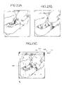
- FIG. 12A is a view of an example of the former time-series image
- FIG. 12B is a view of an example of the process target image
- FIG. 12C is a view in which motion vectors calculated based on the former time-series image of FIG. 12A and the process target image of FIG. 12B are shown in the process target image;
- FIG. 13 is a flowchart of process procedures of a depth-direction movement determination process
- FIG. 14 is a view of an example of center point candidates set in the process target image
- FIG. 15A is an explanatory diagram for explaining how depth center point is selected
- FIG. 15B is another explanatory diagram for explaining how depth center point is selected.
- FIG. 16 is a graph of an example of depth-determination inner-product threshold
- FIG. 17 is a graph of an example of front-determination inner-product threshold
- FIG. 18A is a view of an example of the former time-series image
- FIG. 18B is a view of an example of the process target image
- FIG. 18C is a view in which motion vectors calculated based on the former time-series image of FIG. 18A and the process target image of FIG. 18B are shown in the process target image;
- FIG. 19A is a view of an example of the former time-series image
- FIG. 19B is a view of an example of the process target image
- FIG. 19C is a view in which motion vectors calculated based on the former time-series image of FIG. 19A and the process target image of FIG. 19B are shown in the process target image;
- FIG. 20A is a view of an example of the former time-series image
- FIG. 20B is a view of an example of the process target image
- FIG. 20C is a view in which motion vectors calculated based on the former time-series image of FIG. 20A and the process target image of FIG. 20B are shown in the process target image;
- FIG. 21 is a flowchart of detailed process procedures of an off-vector search process
- FIG. 22 is a flowchart of detailed process procedures of a newly-appearing-image-rate estimation process
- FIG. 23A is a view of an example of the former time-series image
- FIG. 23B is a view of an example of the process target image, for which a motion pattern found between the former time-series image of FIG. 23A is classified as “parallel movement”;
- FIG. 23C is a view of a newly-appeared region estimated in the process target image of FIG. 23B ;
- FIG. 24A is a view of an example of the former time-series image
- FIG. 24B is a view of an example of the process target image, for which a motion pattern found between the former time-series image of FIG. 24A is classified as “movement toward front side in depth direction”;
- FIG. 24C is a view of a newly-appeared region estimated in the process target image of FIG. 24B ;
- FIG. 25A is a view of an example of the former time-series image
- FIG. 25B is a view of an example of the process target image, for which a motion pattern found between the former time-series image of FIG. 25A is classified as “movement toward deeper side in depth direction”;
- FIG. 25C is a view of a newly-appeared region estimated in the process target image of FIG. 25B ;
- FIG. 26 is an explanatory diagram for explaining how the newly-appeared region is estimated when the image motion pattern is “movement toward deeper side in depth direction”.
- FIG. 27 is a graph of an example of conversion curve for converting a newly-appearing rate into a display-time determination coefficient.
- FIG. 1 is a schematic diagram of an overall configuration of an image processing system including an image processing apparatus according to an embodiment.
- the image processing apparatus of the embodiment is an image processing apparatus that processes and displays an image picked up by a capsule endoscope inside a body cavity.
- the image processing system includes a capsule endoscope 3 , a receiving apparatus 4 , an image processing apparatus 70 , and the like.
- the capsule endoscope 3 picks up an image (intra-body image) inside a subject 1 .
- the receiving apparatus 4 receives an intra-body image radio transmitted by the capsule endoscope 3 .
- the image processing apparatus 70 processes and displays the intra-body image picked up by the capsule endoscope 3 based on the intra-body image received by the receiving apparatus 4 .
- Image data is transferred between the receiving apparatus 4 and the image processing apparatus 70 with the use of a recording medium of a portable type (portable recording medium) 5 , for example.
- the capsule endoscope 3 has an imaging function, a radio communication function, and the like, and is swallowed by the subject 1 from the mouth for the introduction into the subject 1 , and sequentially picks up intra-body images while traveling through body cavities. Then, the capsule endoscope 3 radio transmits the picked-up intra-body images to an outside of the body.
- the receiving apparatus 4 has plural receiving antennas A 1 to An, to receive the intra-body image radio transmitted by the capsule endoscope 3 via the respective receiving antennas A 1 to An.
- the receiving apparatus 4 is so configured that the portable recording medium 5 can be attached/detached thereto/therefrom so as to sequentially store image data of the received intra-body image in the portable recording medium 5 .
- the receiving apparatus 4 accumulates intra-body images picked up by the capsule endoscope 3 inside the subject 1 in the portable recording medium 5 in an order of time series.
- the receiving antennas A 1 to An are configured with, for example, loop antennas, and are distributively arranged at predetermined positions on a body surface of the subject 1 as shown in FIG. 1 .
- the receiving antennas A 1 to An are distributively arranged on the body surface at positions corresponding to the travelling route of the capsule endoscope 3 in the subject 1 , for example.
- the receiving antennas A 1 to An may be distributively arranged on a jacket the subject 1 wears. Then, when the subject 1 wears the jacket, the receiving antennas A 1 to An are arranged on the body surface of the subject 1 at predetermined positions corresponding to the travelling route of the capsule endoscope 3 in the subject.
- the number of the receiving antennas is not limited.
- the image processing apparatus 70 is realized with a general computer such as a workstation and a personal computer, and is so configured that the portable recording medium 5 is attachable/detachable thereto/therefrom.
- the image processing apparatus 70 acquires intra-body images in time series as accumulated in the portable recording medium 5 and successively displays the time-series intra-body images as acquired on a display such as an LCD or an ELD by sequentially switching from one image to another.
- FIG. 2 is a block diagram for explaining a functional configuration of the image processing apparatus 70 .
- the image processing apparatus 70 includes an image acquiring unit 710 , an input unit 720 , a display unit 730 , a storage unit 740 , an image processing unit 750 , and a control unit 760 which controls each unit of the apparatus.
- the image acquiring unit 710 acquires time-series intra-body images as picked up by the capsule endoscope 3 .
- the portable recording medium 5 is detachably attached to the image acquiring unit 710 , and the image acquiring unit 710 reads out and thus acquires the image data of the time-series intra-body images accumulated in the attached portable recording medium 5 .
- the image acquiring unit 710 is realized, for example, with a reader/writer compatible with the type of the portable recording medium 5 .
- the acquisition of the time-series intra-body images picked up by the capsule endoscope 3 is not limited to the acquisition with the use of the portable recording medium 5 .
- a hard disk may be provided in place of the image acquiring unit 710 , so that the time-series intra-body images picked up by the capsule endoscope 3 are stored in the hard disk in advance.
- a separate server may be provided in place of the portable recording medium 5 , so that the time-series intra-body images are stored in the server in advance.
- the image acquiring unit 710 is configured with a communication device or the like so as to be connected to the server, and the apparatus is connected to the server via the image acquiring unit 710 so as to acquire the time-series intra-body images from the server.
- the input unit 720 is realized, for example, with a keyboard, a mouse, a touch panel, various types of switches, or the like, to output an operation signal corresponding to an operation input to the control unit 760 .
- the display unit 730 is realized with a display device such as an LCD and an ELD, to display various types of screens including a display screen of a time-series intra-body image under the control of the control unit 760 .
- the image processing unit 750 is realized with a hardware such as a CPU.
- the image processing unit 750 processes plural intra-body images, which are time-series images acquired by the image acquiring unit 710 , and performs various types of arithmetic processes to calculate a display-time determination coefficient for determining a display time of the display of each intra-body image on the display unit 730 .
- the image processing unit 750 includes a motion-vector calculating unit 751 , an image-motion-pattern classifying unit 752 , an off-vector search unit 753 , a newly-appearing-image-rate estimating unit 754 , and a display-time determination coefficient calculating unit 755 .
- the image-motion-pattern classifying unit 752 can be referred to as a motion-pattern classifying unit.
- the off-vector search unit 753 can be referred to as an off-pattern-vector extracting unit.
- the newly-appearing-image-rate estimating unit 754 can be referred to as a newly-appearing-rate estimating unit.
- the display-time determination coefficient calculating unit 755 can be referred to as a display-time calculating unit.
- the motion-vector calculating unit 751 associates an identical object appears in different intra-body images with each other to calculate vector data (motion vector) representing the amount of change of the position of the object.
- the image-motion-pattern classifying unit 752 classifies a motion pattern of each intra-body image (hereinafter referred to as “image motion pattern”), in other words, a motion pattern of the capsule endoscope 3 at the time of image pickup of each intra-body image. Specifically, the image-motion-pattern classifying unit 752 classifies as one of image motion patterns including “no-motion”, “parallel movement”, “movement toward deeper side in depth direction”, “movement toward front side in depth direction”, and “scene change” based on the motion vector.
- the off-vector search unit 753 searches the motion vectors of each intra-body image for a motion vector which is off from the image motion pattern of the intra-body image and extracts the found vector as an off-vector.
- the newly-appearing-image-rate estimating unit 754 estimates a region which does not exist in a former time-series image and newly appears in a pertinent intra-body image (hereinafter referred to as “newly-appeared region”) for each intra-body image, and calculates the rate of the newly-appeared region as a newly-appearing rate.
- the display-time determination coefficient calculating unit 755 calculates a display-time determination coefficient which is a calculation parameter for determining a display time of each intra-body image based on the newly-appearing rate.
- the control unit 760 is realized with a hardware such as a CPU.
- the control unit 760 transfers, for example, the image data of the intra-body image supplied from the image acquiring unit 710 , operation signals supplied from the input unit 720 , and an instruction and data to each unit constituting the image processing apparatus 70 according to a program, data, and the like stored in the storage unit 740 .
- the control unit 760 thus controls an operation of the image processing apparatus 70 as a whole in an integrated manner.
- the control unit 760 includes an image display control unit 761 which controls the display of the time-series intra-body images supplied by the image acquiring unit 710 so that the time-series intra-body images are sequentially displayed in an order of time series on the display unit 730 for a display time of each.
- the storage unit 740 is realized, for example, with an IC memory of various types, such as a store-updatable flash memory, a ROM, and a RAM, a hard disk which is embedded or connected via a data communication terminal, an information recording medium such as a CD-ROM and a reader device of the medium, and the like.
- the storage unit 740 stores therein a program related with the operation of the image processing apparatus 70 , a program for realizing various types of functions of the image processing apparatus 70 , data related with the execution of these programs, and the like. Further, the storage unit 740 stores display-time determination coefficient data 741 in which a display-time determination coefficient of each intra-body image calculated by the display-time determination coefficient calculating unit 755 is stored.
- the data of the display-time determination coefficient may be written into the portable recording medium 5 in association with each intra-body image.
- the storage unit 740 stores therein an image processing program 743 for making the image processing unit 750 work as the motion-vector calculating unit 751 , the image-motion-pattern classifying unit 752 , the off-vector search unit 753 , the newly-appearing-image-rate estimating unit 754 , and the display-time determination coefficient calculating unit 755 .
- FIG. 3 is an overall flowchart of process procedures performed by the image processing apparatus 70 .
- the processes described here are realized when the image processing unit 750 reads out and executes the image processing program 743 stored in the storage unit 740 .
- the motion-vector calculating unit 751 performs a motion-vector calculation process (step S 1 ).
- the image-motion-pattern classifying unit 752 performs an image-motion-pattern classification process (step S 2 ).
- the off-vector search unit 753 performs an off-vector search process (step S 3 ).
- the newly-appearing-image-rate estimating unit 754 performs a newly-appearing-image-rate estimation process (step S 4 ).
- the display-time determination coefficient calculating unit 755 performs a display-time determination coefficient calculation process (step S 5 ).
- the display-time determination coefficient of each intra-body image is obtained.
- the image display control unit 761 controls so that the intra-body images are sequentially displayed on the display unit 730 in an order of time series each for a display time determined by the display-time determination coefficient.
- the process for calculating the display-time determination coefficient of each intra-body image may be performed in the image processing apparatus, and the intra-body images may be sequentially displayed in an order of time series each for a display time determined by the display-time determination coefficient on an apparatus separate from the image processing apparatus. Details of the processes performed in steps S 1 to S 5 are described below with a focus on how the display-time determination coefficient of one intra-body image (hereinafter referred to as “process target image” as appropriate) is found.
- the motion-vector calculating unit 751 performs template matching using plural pixel regions set in the intra-body image as templates. Then, the motion-vector calculating unit 751 calculates a motion vector of each template position relative to the intra-body image which is acquired before in the time series (hereinafter referred to as “former time-series image” as appropriate), for example.
- FIG. 4A is a view of an example of the former time-series image
- FIG. 4B is a view of an example of the process target image
- FIG. 4C is a view of motion vectors in the process target image calculated based on the former time-series image of FIG. 4A and the process target image of FIG. 4B .
- the motion-vector calculating unit 751 first sets pixel regions 101 of a predetermined number ( 16 , for example) in the former time-series image as shown in FIG. 4A .
- the position, size, number, and the like of the pixel regions to be set may be previously determined, or configured to be settable and changeable according to a user operation or the like.
- the motion-vector calculating unit 751 sequentially uses each pixel region 101 as a template to perform a known template matching process, and searches for a position which matches with the template to a highest degree (in other words, a position with a high correlation value) in the process target image.
- template matching matching based on normalization cross-correlation is employed, for example. More specifically, for higher-speed processing, a technique of multi-resolution pyramid search is employed, according to which a matching region is sequentially searched from a low-resolution image and a search range is narrowed down.
- the motion-vector calculating unit 751 calculates an average pixel value of each pixel region in the former time-series image employed as a template, and does not perform template matching for a dark pixel region whose average pixel value is not higher than a predetermined threshold, and treats the matching of this region as failure. Similarly, when the matching region cannot be found in the course of matching search based on the multi-resolution pyramid search, or when the obtained correlation value is low, the motion-vector calculating unit 751 treats the process as matching failure. As a result of template matching, template positions 103 which are most similar to respective pixel regions 101 of FIG. 4A are found from the process target image as shown in FIG. 4B , and the correlation values thereof are found.
- the motion-vector calculating unit 751 calculates motion vectors 105 based on the found template positions 103 , or more specifically, template positions 103 found as a result of search and for which the matching is successful.
- Data on the result of matching obtained through the motion-vector calculation process is stored in the storage unit 740 .
- failure or success of the matching an obtained template position, a correlation value of the obtained template position, a motion vector, and the like are stored in association with an identification number of a pixel region employed as a template.
- FIG. 5 is a flowchart of detailed process procedures of the image-motion-pattern classification process.
- the image-motion-pattern classifying unit 752 first compares the number of matching successes in the motion-vector calculation process which is an example of a confidence value and a reference number of successes previously set as a threshold. Then, when the number of matching successes is equal to or smaller than the reference number of successes (Yes in step S 11 ), the image-motion-pattern classifying unit 752 proceeds to step S 27 and classifies the pertinent image motion pattern as “scene change”.
- FIG. 6A is a view of an example of the former time-series image
- FIG. 6B is a view of an example of the process target image
- FIG. 6C is a view of motion vectors in the process target image calculated based on the former time-series image of FIG.
- the image-motion-pattern classifying unit 752 performs a no-motion determination process (step S 13 ) as shown in FIG. 5 .
- FIG. 7 is a flowchart of process procedures of the no-motion determination process.
- the image-motion-pattern classifying unit 752 first determines whether the number of vectors obtained as a result of successful matching (i.e., matching vector number) is equal to or smaller than a predetermined number previously set as a threshold for determination in step S 31 .
- the image-motion-pattern classifying unit 752 selects a motion vector which has a maximum size and excludes the same as an off-value from process target subsequent to step S 35 (step S 33 ). In the motion vector calculation process, the motion vector is sometimes obtained at an incorrect matching position.
- the image-motion-pattern classifying unit 752 calculates an average value of the size of the motion vector based on the motion vectors other than the motion vector excluded as the off-value (step S 35 ). Then, the image-motion-pattern classifying unit 752 sets a vector average threshold corresponding to the matching vector number (step S 37 ).
- FIG. 8 is a graph for explaining how the vector average threshold is set, where a horizontal axis represents the matching vector number and a vertical axis represents the vector average threshold, and an example of the vector average threshold set corresponding to the matching vector number is shown. As shown in FIG. 8 , the vector average threshold is set so that the threshold becomes smaller as the matching vector number decreases. This is because, when the number of motion vectors employed for the no-motion determination is small, it becomes more likely that the image motion pattern of the process target image accidentally falls into the category of “no-motion”.
- the vector average threshold is calculated according to following equation (1) based on a reference vector average threshold previously set.
- V s ′ represents the vector average threshold
- V s represents the reference vector average threshold
- p represents the number of motion vectors for which the matching is successful (i.e., matching vector number)
- N represents the number of motion vectors when all the matching are successful (N corresponds to the number of pixel regions set in the former time-series image)
- ⁇ s represents conversion coefficient.
- V s ′ V s ⁇ ( p N ) ⁇ s ( 1 )
- the image-motion-pattern classifying unit 752 determines on the average value of the size of the motion vector calculated in step S 35 as shown in FIG. 7 .
- the image-motion-pattern classifying unit 752 classifies the image motion pattern of the process target image as “no-motion” (step S 41 ).
- the image motion pattern of the process target image is classified as “no-motion” when the average value of the size of the motion vector calculated in step S 35 is equal to or smaller than the vector average threshold set in step S 37 , though the manner of classification is not limited thereto.
- FIG. 9A is a view of an example of the former time-series image
- FIG. 9B is a view of an example of the process target image
- FIG. 9C is a view of motion vectors in the process target image calculated based on the former time-series image of FIG. 9A and the process target image of FIG. 9B .
- step S 15 the image-motion-pattern classifying unit 752 determines whether the image motion pattern is “no-motion” or not.
- the image motion pattern is classified as “no-motion” as a result of the no-motion determination process in step S 13 (Yes in step S 15 )
- the image-motion-pattern classifying unit 752 finishes the process.
- the image-motion-pattern classifying unit 752 performs a parallel movement determination process (step S 17 ).
- FIG. 10 is a flowchart of process procedures of the parallel movement determination process.
- the image motion pattern of the intra-body image is “parallel movement”, all the motion vectors have similar size and direction.
- the parallel movement determination process it is determined whether the image motion pattern is “parallel movement” or not based on the direction of each motion vector.
- the image-motion-pattern classifying unit 752 first determines whether the matching vector number is equal to or smaller than a predetermined value previously set as a threshold for the determination in step S 51 .
- the image-motion-pattern classifying unit 752 calculates the average of the angle (direction) of the motion vector to select a motion vector for which the absolute value of difference from the average angle is the largest. Then, the image-motion-pattern classifying unit 752 excludes the selected vector as an off-value from process target of step S 55 and subsequent steps (step S 53 ).
- This process similarly to the no-motion determination process, aims at enhancing the determination accuracy by taking into consideration a case where the matching is performed at an incorrect position at the time of motion vector calculation. Hence, when the matching vector number of successful matching is equal to or smaller than the predetermined number (Yes in step S 51 ), the off-value exclusion process of step S 53 is not performed.
- the image-motion-pattern classifying unit 752 calculates fluctuation of the angle of the motion vector based on the motion vectors other than the motion vector excluded as the off-value (step S 55 ).
- angular variance is calculated as the fluctuation of the angle.
- the image-motion-pattern classifying unit 752 sets a vector angular variance threshold corresponding to the matching vector number (step S 57 ).
- FIG. 11 is a graph for explaining how the vector angular variance threshold is set, where a horizontal axis represents the matching vector number and a vertical axis represents the vector angular variance threshold, and an example of the vector angular variance threshold set corresponding to the matching vector number is shown. As shown in FIG.
- the vector angular variance threshold is set so that the threshold becomes smaller as the matching vector number decreases. This is because when the number of motion vectors employed for the parallel movement determination is small, it becomes more likely that the image motion pattern of the process target image accidentally falls into the category of “parallel movement”.
- the vector angular variance threshold is calculated according to following equation (2) based on a reference vector angular variance threshold previously set.
- V p ′ represents the vector angular variance threshold
- V p represents the reference vector angular variance threshold
- p represents the number of motion vectors for which the matching is successful
- N represents the number of motion vectors when all matching is successful
- ⁇ p represents conversion coefficient.
- V p ′ V p ⁇ ( p N ) ⁇ p ( 2 )
- the image-motion-pattern classifying unit 752 determines on the angular variance of the motion vector calculated in step S 55 as shown in FIG. 10 .
- the image-motion-pattern classifying unit 752 classifies the image motion pattern of the process target image as “parallel movement” (step S 61 ).
- FIG. 12A is a view of an example of the former time-series image
- FIG. 12B is a view of an example of the process target image
- FIG. 12C is a view of motion vectors in the process target image calculated based on the former time-series image of FIG.
- the image motion pattern is classified as “parallel movement”. Then, the image-motion-pattern classifying unit 752 returns to step S 17 of FIG. 5 and proceeds to step S 19 .
- step S 19 the image-motion-pattern classifying unit 752 determines whether the image motion pattern is “parallel movement” or not.
- the image motion pattern is “parallel movement”, in other words, when the image motion pattern is classified as “parallel movement” as a result of the parallel movement determination process in step S 17 (Yes in step S 19 ), the image-motion-pattern classifying unit 752 finishes the process.
- the image-motion-pattern classifying unit 752 performs a depth-direction movement determination process (step S 21 ).
- FIG. 13 is a flowchart of process procedures of the depth-direction movement determination process.
- the image-motion-pattern classifying unit 752 first sets a predetermined number of center point candidates in the process target image (step S 71 ).
- FIG. 14 is a view of an example of center point candidates set in the process target image, wherein plural center point candidates 141 are arranged and set in the process target image. The position of each of the center point candidates 141 and the number thereof are previously set.
- the image-motion-pattern classifying unit 752 selects a depth center point from the center point candidates 141 .
- the depth center point corresponds to a point which indicates a destination of the capsule endoscope 3 in the image, in other words, an advancing-direction position which is a position where the advancing direction of the movement of the capsule endoscope 3 appears in the image.
- the image-motion-pattern classifying unit 752 selects the center point candidate 141 which is closest to the advancing-direction position of the capsule endoscope 3 in the process target image, and sets the selected point as the depth center point.
- the image-motion-pattern classifying unit 752 calculates a vector connecting the center point candidate with an origin of each motion vector for each of the center point candidates (hereinafter, such vector is referred to as “origin vector”). Subsequently, the image-motion-pattern classifying unit 752 calculates an inner product of each origin vector calculated with respect to each center point candidate and a motion vector whose origin is an end point of the origin vector (hereinafter referred to as “motion-vector inner product”) (step S 73 ).
- the image-motion-pattern classifying unit 752 calculates the average of the motion-vector inner product for each center point candidate (step S 75 ), and selects as the depth center point, a center point candidate for which the absolute value of the calculated average of the motion-vector inner product is maximum (step S 77 ).
- FIGS. 15A and 15B are explanatory diagrams for explaining how the depth center point is selected.
- the motion pattern of the process target image is “movement toward deeper side in depth direction” or “movement toward front side in depth direction”.
- the direction of each origin vector which connects the center point candidate 143 and the origin of each motion vector is close to the direction of the motion vector whose origin is a position indicated by the origin vector.
- the origin vector and the motion vector are forward-directed, whereas for the “movement toward front side in depth direction”, these are backward-directed.
- the motion vector sometimes becomes 0 vector.
- the motion-vector inner product is set to be “1.0”, whereas when the average is negative, the motion-vector inner product is set to “ ⁇ 1.0”.
- the image-motion-pattern classifying unit 752 calculates the sum of the number of matching failures and the number of motion vectors for which the absolute value of motion-vector inner product from the depth center point is equal to or smaller than the previously set reference inner product, in other words, the number of motion vectors whose direction does not coincide with the direction of origin vector (corresponding to the depth direction), as shown in FIG. 13 . Then, when the calculated number is smaller than a predetermined number previously set as a threshold for determination in step S 79 (No in step S 79 ), the image-motion-pattern classifying unit 752 proceeds to step S 81 . When the calculated number is equal to or larger than the predetermined number (Yes in step S 79 ), the process ends.
- step S 81 and subsequent steps in the depth-direction movement determination is not performed.
- a motion vector for which the motion-vector inner product is equal to or smaller than a predetermined lower limit inner product is determined to be a vector whose direction does not coincide with the direction of origin vector.
- a motion vector for which the motion-vector inner product is equal to or larger than a predetermined upper limit inner product is determined to be a vector whose direction does not coincide with the direction of origin vector. Then, it is determined whether the sum of the number of motion vectors whose direction does not coincide with the direction of origin vector and the number of matching failures is equal to or larger than a predetermined number.
- step S 81 the image-motion-pattern classifying unit 752 sets a depth-determination inner-product threshold and a front-determination inner-product threshold based on the matching vector number.
- FIG. 16 is a graph for explaining how the depth-determination inner-product threshold is set, where a horizontal axis represents the matching vector number while a vertical axis represents the depth-determination inner-product threshold, and an example of depth-determination inner-product threshold set corresponding to the matching vector number is shown. As shown in FIG. 16 , the depth-determination inner-product threshold is set so that the value thereof approaches “1” as the matching vector number decreases.
- the depth-determination inner-product threshold is calculated according to following equation (3) based on a reference depth-determination inner-product threshold previously set.
- V b ′ represents the depth-determination inner-product threshold
- V b represents the reference depth-determination inner-product threshold
- p represents the number of motion vectors for which the matching is successful
- N represents the number of motion vectors when all matching is successful
- ⁇ b represents conversion coefficient.
- V b ′ V b ⁇ ( N p ) ⁇ b ( 3 )
- FIG. 17 is a graph for explaining how the front-determination inner-product threshold is set, where a horizontal axis represents the matching vector number while a vertical axis represents the front-determination inner-product threshold, and an example of front-determination inner-product threshold set corresponding to the matching vector number is shown.
- the front-determination inner-product threshold is set so that the value thereof approaches “ ⁇ 1” as the matching vector number decreases. This is because when the number of motion vectors employed for the depth-direction movement determination is small, it becomes more likely that the image motion pattern of the process target image accidentally falls into the category of “movement toward front side in depth direction”. Therefore the front-determination inner-product threshold is set low.
- the front-determination inner-product threshold is calculated according to following equation (4) based on a reference front-determination inner-product threshold previously set.
- V d ′ represents the front-determination inner-product threshold
- V d represents the reference front-determination inner-product threshold
- p represents the number of motion vectors for which the matching is successful
- N represents the number of motion vectors when all matching is successful
- ⁇ d represents conversion coefficient.
- V d ′ V d ⁇ ( N p ) ⁇ d ( 4 )
- the image-motion-pattern classifying unit 752 determines on the average of motion-vector inner products calculated for the depth center in step S 75 as shown in FIG. 13 .
- the image-motion-pattern classifying unit 752 classifies, when the average of motion-vector inner products is equal to or larger than the depth-determination inner-product threshold set in step S 81 (Yes in step S 83 ), the image motion pattern of the process target image as “movement toward deeper side in depth direction” (step S 85 ).
- the image motion pattern of the process target image is classified as “movement toward deeper side in depth direction” when the average of motion-vector inner products calculated for the depth center in step S 75 is equal to or larger than the depth-determination inner-product threshold set in step S 81 , though the manner of classification is not limited thereto.
- such configuration is possible in which the image motion pattern of the process target image is classified as “movement toward deeper side in depth direction” when at least one of values including the average value, minimum value, and fluctuation of the motion-vector inner product is within a range of threshold set for the determination of “movement toward deeper side in depth direction”.
- FIG. 18A is a view of an example of the former time-series image
- FIG. 18B is a view of an example of the process target image
- FIG. 18C is a view of motion vectors in the process target image calculated based on the former time-series image of FIG. 18A and the process target image of FIG. 18B .
- a depth center point 151 is shown in FIG. 18C .
- FIG. 18C when each of motion vectors 153 is directed in substantially the same direction with a corresponding origin vector (direction from the depth center point 151 to the motion vector), the image motion pattern is classified as “movement toward deeper side in depth direction”.
- the image-motion-pattern classifying unit 752 determines on the average of motion-vector inner products calculated for the depth center in step S 75 as shown in FIG. 13 .
- the image-motion-pattern classifying unit 752 classifies, when the average of motion-vector inner products is equal to or smaller than the front-determination inner-product threshold set in step S 81 (Yes in step S 87 ), the image motion pattern of the process target image as “movement toward front side in depth direction” (step S 89 ).
- the image motion pattern of the process target image is classified as “movement toward front side in depth direction” when the average of motion-vector inner products calculated for the depth center in step S 75 is equal to or smaller than the front-determination inner-product threshold set in step S 81 , though the manner of classification is not limited thereto.
- such configuration is possible in which the image motion pattern of the process target image is classified as “movement toward front side in depth direction” when at least one of values including the average value, maximum value, and fluctuation of the motion-vector inner product is within a range of threshold set for the determination of “movement toward front side in depth direction”.
- FIG. 19A is a view of an example of the former time-series image
- FIG. 19B is a view of an example of the process target image
- FIG. 19C is a view of motion vectors in the process target image calculated based on the former time-series image of FIG. 19A and the process target image of FIG. 19B .
- a depth center point 161 is shown in FIG. 19C .
- the image motion pattern is classified as “movement toward deeper side in depth direction” when the average of motion-vector inner products is equal to or larger than the depth-determination inner-product threshold, though the image motion pattern can be classified based on an angle formed by the motion vector and the origin vector.
- the movement is determined to be toward the depth direction when the calculated average of angle formed by each of the motion vectors and the origin vector is equal to or smaller than a predetermined value previously set as a threshold.
- the image motion pattern may be classified as “movement toward deeper side in depth direction”, while the image motion pattern is classified as “movement toward front side in depth direction” when the motion vector and the origin vector are substantially in opposite directions from each other.
- the image-motion-pattern classifying unit 752 returns to step S 21 of FIG. 5 and proceeds to step S 23 .
- step S 23 the image-motion-pattern classifying unit 752 determines whether the image motion pattern is “movement toward deeper side in depth direction” or not.
- image motion pattern is classified as “movement toward deeper side in depth direction” as a result of the depth-direction movement determination process in step S 21 (Yes in step S 23 )
- the image-motion-pattern classifying unit 752 finishes the process.
- the image motion pattern is not “movement toward deeper side in depth direction” (No in step S 23 )
- the image-motion-pattern classifying unit 752 determines whether the image motion pattern is “movement toward front side in depth direction” or not.
- the image-motion-pattern classifying unit 752 finishes the process.
- the image-motion-pattern classifying unit 752 classifies the image motion pattern as “scene change” (step S 27 ).
- the image-motion-pattern classifying unit 752 classifies the image motion pattern as “scene change” even when the number of templates for which the matching is successful is determined to be larger than the reference number of successes in step S 11 , if the image motion pattern is not set as any of “no-motion”, “parallel movement”, “movement toward deeper side in depth direction”, and “movement toward front side in depth direction” in the process from step S 13 to step S 25 .
- FIG. 20A is a view of an example of the former time-series image
- FIG. 20B is a view of an example of the process target image
- FIG. 20C is a view of motion vectors in the process target image calculated based on the former time-series image of FIG. 20A and the process target image of FIG.
- the image motion pattern is classified as “scene change”. Such can happen, for example, when the motion vector is calculated at an incorrect matching position due to lack of position where the correct template matching can be performed, or when the mucosal membrane in the body cavity actually moves irregularly when the capsule endoscope 3 picks up its image.
- the image-motion-pattern classifying unit 752 returns to step S 2 of FIG. 3 and proceeds to step S 3 .
- the result of classification in the image-motion-pattern classification process is stored in the storage unit 740 .
- the off-vector search process in step S 3 of FIG. 3 is described.
- the off-vector search process from an intra-body image which is classified as one of “parallel movement”, “movement toward deeper side in depth direction”, and “movement toward front side in depth direction” among the image motion patterns, a motion vector which does not match the selected image motion pattern is searched and extracted as an off-vector.
- the image motion pattern is changed to “scene change”.
- the motion vector which is set as an off-vector in the off-vector search process is not employed as a target of the newly-appearing-image-rate estimation process in a subsequent stage.
- FIG. 21 is a flowchart of detailed process procedures of the off-vector search process.
- the off-vector search unit 753 first counts the number of matching failures as an off-vector number (step S 91 ).
- the off-vector search unit 753 determines the image motion pattern of the process target image.
- the off-vector search unit 753 calculates the difference between each motion vector in the process target image and the average angle of the motion vector in the process target image calculated in step S 55 of FIG. 10 .
- the off-vector search unit 753 updates the count of the off-vector number by treating the motion vector as an off-vector when the calculated difference is equal to or larger than a predetermined value previously set as a threshold for determination in step S 95 (step S 95 ).
- the off-vector search unit 753 updates the count of off-vector number by treating the motion vector as an off-vector when the motion-vector inner product calculated in step S 73 of FIG. 13 is equal to or smaller than a predetermined value previously set as a threshold for determination in step S 99 (step S 99 ).
- the off-vector search unit 753 determines on the motion-vector inner product calculated in step S 73 of FIG. 13 .
- the off-vector search unit 753 updates the count of the off-vector number by treating the motion vector as an off-vector when the motion-vector inner product is equal to or larger than a predetermined value previously set as a threshold for determination in step S 103 (step S 103 ).
- the off-vector search unit 753 determines the counted off-vector number.
- the off-vector search unit 753 changes the image motion pattern of the process target image to “scene change” (step S 107 ).
- the off-vector search unit 753 returns to step S 3 of FIG. 3 and proceeds to step S 4 .
- a newly-appearing rate i.e., a rate of a region which is newly generated in the process target image after the former time-series image is calculated according to the image motion pattern determined as a result of classification. For example, a possible range of the newly-appearing rate is set from “0.0” to “1.0”, and the value of the newly-appearing rate is estimated to approach “1.0” as the change from the former time-series image becomes larger. If there is no change in images, the newly-appearing rate is estimated to be “0.0”.
- FIG. 22 is a flowchart of detailed process procedures of the newly-appearing-image-rate estimation process.
- the newly-appearing-image-rate estimating unit 754 determines the image motion pattern of the process target image.
- the image motion pattern is “no-motion” (Yes in step S 111 )
- the image can be considered to have undergone insignificant changes, and therefore, the newly-appearing rate is set to “0.0” (step S 113 ).
- the newly-appearing-image-rate estimating unit 754 performs estimation of the newly-appeared region appeared from the edge of the image and calculates the newly-appearing rate (step S 117 ).
- FIG. 23A is a view of an example of the former time-series image.
- FIG. 23B is a view of an example of the process target image, for which an image motion pattern found between the former time-series image of FIG. 23A is classified as “parallel movement”.
- FIG. 23C is a view of a newly-appeared region estimated in the process target image of FIG. 23B .
- the image motion pattern is “parallel movement”
- a new region which does not appear in the former time-series image is expected to appear in the process target image from the edge of the image corresponding to the motion vector.
- the newly-appearing-image-rate estimating unit 754 estimates the newly-appeared region using a motion vector of a line closest to the image edge with respect to each image edge. Specifically, the newly-appearing-image-rate estimating unit 754 finds the average of motion vector (motion vector average) in the line closest to each image edge, and estimates the newly-appeared region at each image edge based on a projection component in a direction orthogonal to each image edge. For example, when an upper edge of the process target image is focused, a motion vector in an uppermost row 191 is employed as shown in FIG. 23C , and a motion vector average 193 is found as shown outside a frame.
- motion vector average 193 is found as shown outside a frame.
- a region 197 which has the width of a projection component 195 in the direction orthogonal to the upper edge of the image (up-down direction of FIG. 23 ) is estimated as a newly-appeared region at the upper edge of the image.
- a newly-appeared region is estimated for each image edge.
- the rate of the sum of eventually obtained regions 197 and 199 to the entire image is set as a newly-appearing rate.
- those vectors which are counted as off-vectors in the off-vector search process ( FIG. 21 ) are not set as the process target. Further, when all the matching fails and no motion vector is obtained, or when all obtained vectors are off-vectors on the lines closest to the image edges, motion vectors on inner lines are employed for the estimation of the newly-appearing regions at the target image edges.
- FIG. 24A is a view of an example of the former time-series image.
- FIG. 24B is a view of an example of the process target image, for which an image motion pattern found between the former time-series image of FIG. 24A is classified as “movement toward front side in depth direction”.
- FIG. 24C is a view of a newly-appeared region estimated in the process target image of FIG. 24B .
- the image motion pattern is “movement toward front side in depth direction”
- a new region which does not appear in the former time-series image is expected to appear in the process target image from the edge of the image corresponding to the motion vector.
- the newly-appearing-image-rate estimating unit 754 estimates the newly-appeared region using the motion vectors on the line closest to the image edge for each image edge similarly to the case of “parallel movement”. For example, if an upper edge of the process target image is focused, motion vectors in an uppermost row 200 is employed as shown in FIG. 24C , and a motion vector average 201 is found as shown outside a frame. Further, at the left edge of the process target image, a motion vector average 206 is found based on motion vectors 203 , 204 , and 205 other than a motion vector 202 which is counted as the off-vector among the motion vectors in the leftmost column. The rate of the sum of eventually obtained regions 207 , 208 , and 209 to the entire image is set as a newly-appearing rate.
- the newly-appearing-image-rate estimating unit 754 estimates the newly-appeared region with reference to the depth center point and calculates the newly-appearing rate (step S 121 ).
- FIG. 25A is a view of an example of the former time-series image.
- FIG. 25B is a view of an example of the process target image, for which an image motion pattern found between the former time-series image of FIG. 25A is classified as “movement toward deeper side in depth direction”.
- FIG. 25C is a view of a newly-appeared region estimated in the process target image of FIG. 25B .
- the image motion pattern is “movement toward deeper side in depth direction”
- a new region which does not appear in the former time-series image is expected to appear in the process target image from the depth center point.
- the newly-appearing-image-rate estimating unit 754 estimates the newly-appeared region using a predetermined number of motion vectors calculated at template positions near the depth center point. Specifically, the newly-appearing-image-rate estimating unit 754 selects the predetermined number of motion vectors starting from the one whose distance from the depth center point is shorter. Subsequently, the newly-appearing-image-rate estimating unit 754 calculates the length of each projection component in a linear direction connecting the depth center point and the origin of each motion vector, and obtains the average thereof (projection component average).
- the newly-appearing-image-rate estimating unit 754 estimates a rectangular region which has twice the length of the obtained projection component average as its diagonal line with reference to the depth center point as a newly-appeared region.
- the newly-appeared region is estimated based on four vectors 221 to 224 calculated near the depth center point 211 in FIG. 25C .
- FIG. 26 is an explanatory diagram for explaining how the newly-appeared region is estimated when the image motion pattern is “movement toward deeper side in depth direction”, where the depth center point 211 of FIG. 25C and four vectors 221 to 224 nearby are extracted. As shown in FIG.
- projection components 231 to 234 are found for the motion vectors 221 to 224 , respectively, in the linear direction connecting the depth center point 211 and the origin of the motion vector, and the projection component average is obtained.
- the newly-appearing-image-rate estimating unit 754 estimates a rectangular region 213 which has twice the length 215 of the obtained projection component average as its diagonal line with reference to the depth center point 211 as a newly-appeared region.
- the newly-appearing-image-rate estimating unit 754 sets the newly-appearing rate to “1.0” (step S 123 ).
- the display-time determination coefficient calculating unit 755 converts the newly-appearing rate obtained as a result of the newly-appearing-image-rate estimation process into a display-time determination coefficient T using a conversion curve represented by following equation (5).
- T ⁇ S ⁇ (5)
- S represents newly-appearing rate
- ⁇ represents display-time calculation coefficient
- ⁇ represents display-time calculation power coefficient.
- FIG. 27 is a graph of conversion curve represented by the equation (5). It is expected that once the newly-appearing rate S exceeds a predetermined level, an observer finds it difficult to find correspondence between images and feels that the image is substantially a new image. Hence, in the embodiment, a degree at which the observer feels as described above is determined empirically as ⁇ in the equation (5).
- the range of the value of display-time determination coefficient may be made adjustable according thereto.
- the degree of adjustment is empirically determined as ⁇ in the equation (5).
- an object which is present relatively close to the position of the capsule endoscope 3 and appears near the image edge may appears in a different size in the image from an object which is far from the capsule endoscope 3 and appears near the depth center point of the image.
- an observer may feel that the image changes in a manner not proportional to the size of the calculated newly-appeared region when the newly-appeared region starts to appear from the image edge and when the newly-appeared region starts to appear from a portion around the depth center point.
- the image motion pattern is “movement toward deeper side in depth direction”
- a previously obtained newly-appearing rate is multiplied by a predetermined coefficient before the calculation of the display-time determination coefficient T.
- the display-time determination coefficient T takes a value within the range from “0.0” to “1.0”, and takes a value of “0.0” when the image contents does not change substantially from the former time-series image, and the display time becomes shortest.
- the display-time determination coefficient T takes the value of “1.0”, and the image display time becomes longest.
- the found display-time determination coefficient T is employed as a variable of the display time Time of the intra-body image calculated by following equation (6), for example.
- MaxTime represents the longest display time of one intra-body image
- MinTime represents the shortest display time of one intra-body image.
- the intra-body images which are time-series images are classified into the image motion patterns which represent how the image as a whole moves, based on the motion vectors calculated relative to another intra-body image which precedes in time series. Then, the newly-appearing rate of the region which appears anew after the former time-series image is calculated with the use of the motion vector corresponding to the image motion pattern, and the display-time determination coefficient is calculated based on the newly-appearing rate of the image.
- the display time of each of the intra-body images can be adjusted according to the change in the appearance of the image as observed by the observer with the use of the motion vector, whereby each intra-body image can be displayed for an appropriate display time.
- an image, in which a site which does not appear in previous images occupies a large area, would not be skipped or displayed only for a short time.
- the observer would not fail to notice the display contents, and further, as an image in which an already-observed site occupies a large area is displayed only for a short time period, the observation efficiency can be enhanced, and the observer can efficiently grasp the contents of intra-body images.
- the image is classified as one of the image motion patterns including “no-motion”, “parallel movement”, “movement toward deeper side in depth direction”, “movement toward front side in depth direction”, and “scene change”.
- the configuration is described as performing the newly-appearing-image-rate calculation by a manner corresponding to the classification of the image motion pattern, though the present invention is not limited by the embodiment.
- the image motion patterns including “no-motion”, “parallel movement”, “movement toward deeper side in depth direction”, “movement toward front side in depth direction”, and “scene change” as a target of determination, and to make such a configuration that the newly-appearing rate is calculated in a manner corresponding to the classification of the image motion pattern set as the determination target.
- time-series intra-body images picked up by the capsule endoscope 3 is described, though the present invention is not limited thereto.
- the present invention is similarly applicable to a case where time-series images are sequentially displayed, for example, and an image with a high newly-appearing rate may be displayed for a long time, while an image with a low newly-appearing rate may be displayed for a short time, among images constituting the time-series images.
- the display time of the image can be set according to the newly-appearing rate which is a rate of a newly-appeared region in an image. Hence, the observer is prevented from overlooking the display contents, and at the same time, contents of plural images constituting the time-series images can be efficiently grasped.
Abstract
Description
T=α×S γ (5)
Time=(MaxTime−MinTime)×T+MinTime (6)
Claims (34)
Applications Claiming Priority (2)
| Application Number | Priority Date | Filing Date | Title |
|---|---|---|---|
| JP2007176531A JP4959445B2 (en) | 2007-07-04 | 2007-07-04 | Image processing apparatus and image processing program |
| JP2007-176531 | 2007-07-04 |
Publications (2)
| Publication Number | Publication Date |
|---|---|
| US20090010551A1 US20090010551A1 (en) | 2009-01-08 |
| US8107686B2 true US8107686B2 (en) | 2012-01-31 |
Family
ID=40221501
Family Applications (1)
| Application Number | Title | Priority Date | Filing Date |
|---|---|---|---|
| US12/166,520 Active 2030-11-30 US8107686B2 (en) | 2007-07-04 | 2008-07-02 | Image procesing apparatus and image processing method |
Country Status (3)
| Country | Link |
|---|---|
| US (1) | US8107686B2 (en) |
| JP (1) | JP4959445B2 (en) |
| WO (1) | WO2009004890A1 (en) |
Cited By (1)
| Publication number | Priority date | Publication date | Assignee | Title |
|---|---|---|---|---|
| US20100194869A1 (en) * | 2009-01-30 | 2010-08-05 | Olympus Corporation | Scene-change detecting device, computer readable storage medium storing scene-change detection program, and scene-change detecting method |
Families Citing this family (20)
| Publication number | Priority date | Publication date | Assignee | Title |
|---|---|---|---|---|
| CN100514353C (en) * | 2007-11-26 | 2009-07-15 | 清华大学 | Living body detecting method and system based on human face physiologic moving |
| JP2010176570A (en) * | 2009-01-30 | 2010-08-12 | Olympus Corp | Scene change detecting apparatus, scene change detecting program, and scene change detecting method |
| JP5308848B2 (en) * | 2009-01-30 | 2013-10-09 | オリンパス株式会社 | Scene change detection device, scene change detection program, and scene change detection method |
| JP5457688B2 (en) * | 2009-02-04 | 2014-04-02 | オリンパス株式会社 | Image processing apparatus, image processing program, and image processing method |
| JP2012525898A (en) * | 2009-05-08 | 2012-10-25 | コーニンクレッカ フィリップス エレクトロニクス エヌ ヴィ | Real-time scope tracking and branch labeling without electromagnetic tracking and preoperative roadmap scanning |
| TWI432168B (en) * | 2009-12-31 | 2014-04-01 | Univ Nat Yunlin Sci & Tech | Endoscope navigation method and endoscopy navigation system |
| EP2508116B1 (en) * | 2010-09-24 | 2013-11-13 | Olympus Medical Systems Corp. | Image-display device and capsule-type endoscope system |
| JP6035712B2 (en) | 2010-10-26 | 2016-11-30 | 株式会社リコー | Screen sharing service providing system, information processing apparatus, screen sharing service providing method, screen sharing service providing program, and program |
| CN103180718B (en) * | 2010-10-29 | 2016-01-13 | 奥林巴斯株式会社 | Image analysis method and image analysis apparatus |
| CN103189737B (en) * | 2010-10-29 | 2017-05-31 | 奥林巴斯株式会社 | Image analysis method and image analysis apparatus |
| EP2447882B1 (en) * | 2010-10-29 | 2013-05-15 | Siemens Aktiengesellschaft | Method and device for assigning sources and sinks to routes of individuals |
| JP5569357B2 (en) * | 2010-11-19 | 2014-08-13 | 富士通株式会社 | Image processing apparatus, image processing method, and image processing program |
| KR20120073887A (en) * | 2010-12-27 | 2012-07-05 | 삼성전자주식회사 | Image processing apparatus and method for porcessing image thereof |
| JP5792977B2 (en) * | 2011-03-31 | 2015-10-14 | キヤノン株式会社 | Image processing apparatus, image processing method, ophthalmic apparatus, and medical system |
| JP5784404B2 (en) * | 2011-07-29 | 2015-09-24 | オリンパス株式会社 | Image processing apparatus, image processing method, and image processing program |
| JP5997643B2 (en) * | 2013-03-26 | 2016-09-28 | 富士フイルム株式会社 | ENDOSCOPE SYSTEM, PROCESSOR DEVICE, AND OPERATION METHOD |
| JP6150583B2 (en) * | 2013-03-27 | 2017-06-21 | オリンパス株式会社 | Image processing apparatus, endoscope apparatus, program, and operation method of image processing apparatus |
| US9213901B2 (en) * | 2013-09-04 | 2015-12-15 | Xerox Corporation | Robust and computationally efficient video-based object tracking in regularized motion environments |
| JP6249769B2 (en) * | 2013-12-27 | 2017-12-20 | オリンパス株式会社 | Endoscope apparatus, operation method and program for endoscope apparatus |
| JP6339872B2 (en) * | 2014-06-24 | 2018-06-06 | オリンパス株式会社 | Image processing apparatus, endoscope system, and image processing method |
Citations (5)
| Publication number | Priority date | Publication date | Assignee | Title |
|---|---|---|---|---|
| JP2006280792A (en) | 2005-04-04 | 2006-10-19 | Olympus Corp | Image displaying device |
| WO2006123455A1 (en) | 2005-05-20 | 2006-11-23 | Olympus Medical Systems Corp. | Image display device |
| WO2007077672A1 (en) | 2005-12-28 | 2007-07-12 | Olympus Medical Systems Corp. | Image processing device and image processing method in the image processing device |
| US20070268280A1 (en) * | 2004-08-23 | 2007-11-22 | Manabu Fujita | Image Display Apparatus, Image Display Method, and Image Display Program |
| US20080130748A1 (en) * | 2006-12-04 | 2008-06-05 | Atmel Corporation | Highly parallel pipelined hardware architecture for integer and sub-pixel motion estimation |
-
2007
- 2007-07-04 JP JP2007176531A patent/JP4959445B2/en active Active
-
2008
- 2008-06-04 WO PCT/JP2008/060305 patent/WO2009004890A1/en active Application Filing
- 2008-07-02 US US12/166,520 patent/US8107686B2/en active Active
Patent Citations (7)
| Publication number | Priority date | Publication date | Assignee | Title |
|---|---|---|---|---|
| US20070268280A1 (en) * | 2004-08-23 | 2007-11-22 | Manabu Fujita | Image Display Apparatus, Image Display Method, and Image Display Program |
| JP2006280792A (en) | 2005-04-04 | 2006-10-19 | Olympus Corp | Image displaying device |
| WO2006123455A1 (en) | 2005-05-20 | 2006-11-23 | Olympus Medical Systems Corp. | Image display device |
| US20070195165A1 (en) | 2005-05-20 | 2007-08-23 | Olympus Medical Systems Corp. | Image display apparatus |
| WO2007077672A1 (en) | 2005-12-28 | 2007-07-12 | Olympus Medical Systems Corp. | Image processing device and image processing method in the image processing device |
| US20070165932A1 (en) | 2005-12-28 | 2007-07-19 | Olympus Medical Systems Corp. | Image processing device and image processing method in image processing device |
| US20080130748A1 (en) * | 2006-12-04 | 2008-06-05 | Atmel Corporation | Highly parallel pipelined hardware architecture for integer and sub-pixel motion estimation |
Cited By (2)
| Publication number | Priority date | Publication date | Assignee | Title |
|---|---|---|---|---|
| US20100194869A1 (en) * | 2009-01-30 | 2010-08-05 | Olympus Corporation | Scene-change detecting device, computer readable storage medium storing scene-change detection program, and scene-change detecting method |
| US8665326B2 (en) * | 2009-01-30 | 2014-03-04 | Olympus Corporation | Scene-change detecting device, computer readable storage medium storing scene-change detection program, and scene-change detecting method |
Also Published As
| Publication number | Publication date |
|---|---|
| JP4959445B2 (en) | 2012-06-20 |
| US20090010551A1 (en) | 2009-01-08 |
| WO2009004890A1 (en) | 2009-01-08 |
| JP2009011563A (en) | 2009-01-22 |
Similar Documents
| Publication | Publication Date | Title |
|---|---|---|
| US8107686B2 (en) | Image procesing apparatus and image processing method | |
| US20190034800A1 (en) | Learning method, image recognition device, and computer-readable storage medium | |
| CN107920722B (en) | Reconstruction by object detection for images captured from a capsule camera | |
| US8107704B2 (en) | Image processing device, image processing program and image processing method | |
| US9031387B2 (en) | Image processing apparatus | |
| US8665326B2 (en) | Scene-change detecting device, computer readable storage medium storing scene-change detection program, and scene-change detecting method | |
| US20220172828A1 (en) | Endoscopic image display method, apparatus, computer device, and storage medium | |
| US9661995B2 (en) | Capsule endoscope system, operating method of image display, and computer-readable recording medium | |
| CN103313675A (en) | Intraoperative camera calibration for endoscopic surgery | |
| EP2656775B1 (en) | Position detecting apparatus of capsule endoscope and capsule endoscope system | |
| KR20080078078A (en) | Capsule-type medical device, control device for medical use, image processing device for medical use, and program | |
| US9877635B2 (en) | Image processing device, image processing method, and computer-readable recording medium | |
| US20100034436A1 (en) | Image processing apparatus, computer program product and image processing method | |
| JP6411834B2 (en) | Image display apparatus, image display method, and image display program | |
| US20230245311A1 (en) | Endoscopic photographic device, endoscopic photographic method, and endoscopic photographic program | |
| WO2009081669A1 (en) | Image processing device and image processing program | |
| CN113679327B (en) | Endoscopic image acquisition method and device | |
| JP5408850B2 (en) | Image analysis apparatus and image analysis program | |
| Karargyris et al. | A video-frame based registration using segmentation and graph connectivity for Wireless Capsule Endoscopy | |
| JP2009089910A (en) | Photographing direction discriminating apparatus, photographing direction discriminating method, photographing direction discriminating program, and computer-readable recording medium on which photographing direction discriminating program is recorded | |
| JP5308848B2 (en) | Scene change detection device, scene change detection program, and scene change detection method | |
| CN113409312B (en) | Image processing method and device for biomedical images | |
| CN114785948B (en) | Endoscope focusing method and device, endoscope image processor and readable storage medium | |
| CN114708261A (en) | Motion estimation method and device of image acquisition equipment, terminal and storage medium | |
| CN116761075A (en) | Image processing method and device based on endoscope, electronic equipment and storage medium |
Legal Events
| Date | Code | Title | Description |
|---|---|---|---|
| AS | Assignment |
Owner name: OLYMPUS CORPORATION, JAPAN Free format text: ASSIGNMENT OF ASSIGNORS INTEREST;ASSIGNOR:MATSUDA, TAKEHIRO;REEL/FRAME:021417/0858 Effective date: 20080714 |
|
| FEPP | Fee payment procedure |
Free format text: PAYOR NUMBER ASSIGNED (ORIGINAL EVENT CODE: ASPN); ENTITY STATUS OF PATENT OWNER: LARGE ENTITY |
|
| STCF | Information on status: patent grant |
Free format text: PATENTED CASE |
|
| FPAY | Fee payment |
Year of fee payment: 4 |
|
| AS | Assignment |
Owner name: OLYMPUS CORPORATION, JAPAN Free format text: CHANGE OF ADDRESS;ASSIGNOR:OLYMPUS CORPORATION;REEL/FRAME:039344/0502 Effective date: 20160401 |
|
| MAFP | Maintenance fee payment |
Free format text: PAYMENT OF MAINTENANCE FEE, 8TH YEAR, LARGE ENTITY (ORIGINAL EVENT CODE: M1552); ENTITY STATUS OF PATENT OWNER: LARGE ENTITY Year of fee payment: 8 |
|
| MAFP | Maintenance fee payment |
Free format text: PAYMENT OF MAINTENANCE FEE, 12TH YEAR, LARGE ENTITY (ORIGINAL EVENT CODE: M1553); ENTITY STATUS OF PATENT OWNER: LARGE ENTITY Year of fee payment: 12 |