US8104475B2 - Medical tube assemblies - Google Patents
Medical tube assemblies Download PDFInfo
- Publication number
- US8104475B2 US8104475B2 US12/289,819 US28981908A US8104475B2 US 8104475 B2 US8104475 B2 US 8104475B2 US 28981908 A US28981908 A US 28981908A US 8104475 B2 US8104475 B2 US 8104475B2
- Authority
- US
- United States
- Prior art keywords
- tube
- inner cannula
- outer tube
- lip
- patient end
- Prior art date
- Legal status (The legal status is an assumption and is not a legal conclusion. Google has not performed a legal analysis and makes no representation as to the accuracy of the status listed.)
- Active, expires
Links
Images


Classifications
-
- A—HUMAN NECESSITIES
- A61—MEDICAL OR VETERINARY SCIENCE; HYGIENE
- A61M—DEVICES FOR INTRODUCING MEDIA INTO, OR ONTO, THE BODY; DEVICES FOR TRANSDUCING BODY MEDIA OR FOR TAKING MEDIA FROM THE BODY; DEVICES FOR PRODUCING OR ENDING SLEEP OR STUPOR
- A61M16/00—Devices for influencing the respiratory system of patients by gas treatment, e.g. ventilators; Tracheal tubes
- A61M16/04—Tracheal tubes
- A61M16/0465—Tracheostomy tubes; Devices for performing a tracheostomy; Accessories therefor, e.g. masks, filters
-
- A—HUMAN NECESSITIES
- A61—MEDICAL OR VETERINARY SCIENCE; HYGIENE
- A61M—DEVICES FOR INTRODUCING MEDIA INTO, OR ONTO, THE BODY; DEVICES FOR TRANSDUCING BODY MEDIA OR FOR TAKING MEDIA FROM THE BODY; DEVICES FOR PRODUCING OR ENDING SLEEP OR STUPOR
- A61M16/00—Devices for influencing the respiratory system of patients by gas treatment, e.g. ventilators; Tracheal tubes
- A61M16/04—Tracheal tubes
- A61M16/0402—Special features for tracheal tubes not otherwise provided for
- A61M16/0427—Special features for tracheal tubes not otherwise provided for with removable and re-insertable liner tubes, e.g. for cleaning
-
- A—HUMAN NECESSITIES
- A61—MEDICAL OR VETERINARY SCIENCE; HYGIENE
- A61M—DEVICES FOR INTRODUCING MEDIA INTO, OR ONTO, THE BODY; DEVICES FOR TRANSDUCING BODY MEDIA OR FOR TAKING MEDIA FROM THE BODY; DEVICES FOR PRODUCING OR ENDING SLEEP OR STUPOR
- A61M16/00—Devices for influencing the respiratory system of patients by gas treatment, e.g. ventilators; Tracheal tubes
- A61M16/04—Tracheal tubes
- A61M16/0463—Tracheal tubes combined with suction tubes, catheters or the like; Outside connections
-
- A—HUMAN NECESSITIES
- A61—MEDICAL OR VETERINARY SCIENCE; HYGIENE
- A61M—DEVICES FOR INTRODUCING MEDIA INTO, OR ONTO, THE BODY; DEVICES FOR TRANSDUCING BODY MEDIA OR FOR TAKING MEDIA FROM THE BODY; DEVICES FOR PRODUCING OR ENDING SLEEP OR STUPOR
- A61M16/00—Devices for influencing the respiratory system of patients by gas treatment, e.g. ventilators; Tracheal tubes
- A61M16/04—Tracheal tubes
- A61M16/0434—Cuffs
Definitions
- This invention relates to medical tube assemblies.
- Tracheostomy tubes are inserted through a surgically-made opening in the throat so that one end of the tube locates in the trachea and the other end projects externally. Ventilation gas can then be supplied to the patient's airways via the tube or the patient can breath normally through the tube.
- Tracheostomy tubes are often used where prolonged ventilation is required. In use, however, the inside of the tube becomes coated with secretions, which can reduce the flow of gas along the tube and provide a site for bacteria to multiply. Periodic removal and replacement of the tube is relatively traumatic and uncomfortable for the patient, and must be carried out by surgical staff. It is, therefore, preferable to clean the tube, either by using a suction catheter inserted along the bore of the tube or, preferably, by using an inner cannula. Where an inner cannula is used, this is configured to form a close sliding fit within the tube extending along its entire length. The inner cannula remains in place during normal ventilation and, when secretions have built up, it is removed and replaced by a new inner cannula.
- tracheostomy tube assemblies with an outer tube and an inner cannula are described in, for example, GB2056285, U.S. Pat. Nos. 4,315,505, 4,817,598, 5,119,811, 5,184,611, 5,386,826, 6,019,753, 6,135,110, GBO800112.5, WO94/01156 and WO04/101048.
- the cannulae do reduce the cross-sectional area of the effective passage through the tube so it is important for the wall thickness to be as small as possible and for the cannula to be a close sliding fit within the outer tube whilst allowing free insertion and removal. It is also important that the inner cannula does not buckle, or otherwise deform in a manner that would reduce gas flow, when inserted along the outer tube, which may not be smoothly curved.
- the inner cannula should extend along the entire length of the outer tube without projecting from its end and should preferably form an effective seal at the patient end to prevent seepage of material between the inner wall of the inner cannula and the outer wall of the inner cannula.
- a medical tube assembly comprising an outer tube and an inner cannula that is insertable and removable from the outer tube, the outer tube having, in use, a curve or bend along a part at least of its length and an internally-projecting lip towards its patient end adapted to limit insertion of the inner cannula, the lip being provided with a recess located at the outside of the curve of the tube such that, when the inner cannula is not in place, an elongate device can be inserted along the outer tube and slide through the recess beyond the patient end of the outer tube without catching on the lip.
- a medical tube assembly comprising: an outer tube; an inner cannula and a suction catheter, the inner cannula being insertable and removable from the outer tube, the outer tube having, in use, a curve or bend along a part at least of its length, a patient end, a machine end and an internally-projecting lip towards its patient end adapted to limit insertion of the inner cannula, the lip being provided with a recess located at an outside of the curve of the tube such that, when the inner cannula is not in place, the suction catheter can be inserted along the outer tube and slide through the recess beyond the patient end of the outer tube without catching on the lip.
- a tracheostomy tube assembly comprising: an outer tracheostomy tube and an inner cannula, the inner cannula being insertable and removable from the outer tube, the outer tube having, in use, a curve or bend along a part at least of its length, a patient end, a machine end and an internally-projecting lip towards its patient end adapted to limit insertion of the inner cannula, the lip being provided with a recess located at an outside of the curve of the tube such that, when the inner cannula is not in place, an elongate device can be inserted along the outer tube and slide through the recess beyond the patient end of the outer tube and into the trachea without catching on the lip.
- a medical tube adapted to receive an inner cannula within it, the tube having, in use, a curve or bend along a part at least of its length, a patient end, a machine end and an internally-projecting lip towards its patient end adapted to limit insertion of the inner cannula, the lip being provided with a recess located at an outside of the curve of the tube such that, an elongate device can be inserted along the outer tube and slide through the recess beyond the patient end of the outer tube without catching on the lip.
- a method of using a tracheostomy tube assembly comprising the steps of: inserting in a patient a tracheostomy tube assembly of the kind comprising an outer tracheostomy tube and an inner cannula, the outer tube having a patient end, a machine end and an internally-projecting lip towards its patient end adapted to limit insertion of the inner cannula, the lip being provided with a recess located adjacent the posterior surface of the trachea; enabling ventilation via the assembly; removing the inner cannula; inserting an elongate device along the outer tube to slide through the recess and extend beyond the patient end of the outer tube and into the trachea without catching on the lip; removing the elongate device; and inserting a new inner cannula.
- the elongate device may be a suction catheter.
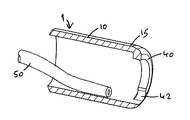
- FIG. 1 shows the assembly schematically
- FIG. 2 is a perspective view of the inner cannula
- FIG. 3 is a cross-sectional side elevation view of the patient end of the outer tube to an enlarged scale
- FIG. 4 is a perspective view of the patient end shown in FIG. 3 ;
- FIG. 5 is a cut-away perspective view of the patient end shown in FIGS. 3 and 4 ;
- FIG. 6 is an end view of the patient end of the outer tube shown in FIGS. 3 to 5 .
- the tracheostomy tube assembly comprises an outer tube 1 and an inner tube or cannula 3 , which is removable from the outer tube so that it can be periodically replaced in the usual way.
- the outer tube 1 has a shaft 10 with straight forward or patient end section 11 and rear or machine end section 12 joined by a right-angle bend section 13 .
- the outer tube could be smoothly curved along its entire length.
- the tube could have a natural straight shape and be highly flexible so that it could be bent during use to the shape of the anatomy.
- Such a flexible tube might be reinforced, such as by a helical wire reinforcement.
- the tube 1 typically has an external diameter of about 11.3 mm and an internal diameter of about 9.3 mm.
- a sealing cuff 14 embraces the shaft 10 close to its patient end 15 ; this can be inflated for sealing, or deflated for insertion and removal, via an inflation line 16 and a combined inflation indicator balloon and coupling 17 .
- the outer tube 1 has a flange 19 to which a tape (not shown) can be attached for securing the assembly around the neck of the patient.
- a hub 20 projects from the machine side of the flange 19 by which gas connection can be made to the tube 1 .
- the tube 1 extends through a tracheostomy with the patient end 15 of the tube 1 located in the trachea.
- the cuff 14 is inflated to form a seal between the outside of the tube 1 and the tracheal wall so that gas flow is confined along the bore of the tube.
- the machine end 18 of the tube 1 extends externally of the tracheostomy.
- the patient end 15 differs from conventional tubes in a manner that will be described in detail later.
- the inner tube or cannula 3 comprises a shaft 30 and a machine end fitting 31 .
- the inner cannula 3 is about 194 mm long and its shaft 30 has an internal diameter of about 8 mm and an external diameter of about 9 mm along the major part of its length.
- the cannula 3 extends as a close sliding fit within the bore of the outer tube 1 with the patient end 32 of the cannula extending to the patient end 15 of the outer tube and with its end fitting 31 locating in the hub 20 of the outer tube.
- the shaft 30 is of ePTFE and is made by cutting from a length of extruded stock tubing.
- the nature of the shaft 30 is that it can flex readily to conform to the shape of the outer tube 1 without kinking as it is inserted.
- the shaft material has a very low coefficient of friction so that it can be inserted readily into the outer tube 1 as a close sliding fit without excessive axial compression forces being produced of a kind that could cause the shaft 30 to buckle.
- the shaft 30 is attached to a machine end fitting 31 in the manner described in detail in GB0800112.5 the contents of which are incorporated herein by reference.
- the patient end 15 of the outer tube 1 is moulded with an inturned, part-annular lip 40 , similar to the annular lip shown U.S. Pat. No. 4,315,515.
- the purpose of this lip 40 is to provide a rear-facing surface 41 , which acts as a stop for the patient end 32 of the inner cannula 3 and thereby prevents it projecting from the patient end 15 of the outer tube 1 .
- the lip 40 also helps, to some extent, to reduce seepage of material between the outside of the inner cannula 3 and the inside of the outer tube 1 .
- the lip 40 does not form a complete annulus but is interrupted by a recess, notch or gap 42 .
- This notch 42 is located on the outside of the bend of the outer tube 1 (that is, the outside of the bend of the tube during use) for a reason that will become apparent later.
- the width W of the notch is about 5 mm and the internal diameter D of the lip is about 7 mm.
- the width of the notch 42 is selected to provide a sufficient gap to allow a suction catheter 50 or other elongate device to be slid along the outer tube 1 , after removal of the inner cannula 3 , and to extend beyond the patient end 15 of the outer tube without catching on the lip 40 .
- the invention is not confined to tracheostomy tube assemblies but could be used in other tube assemblies of an outer and inner tube where an elongate device needs to be insertable freely beyond the patient end of the outer tube.
- the inner cannula could be of any different form.
Landscapes
- Health & Medical Sciences (AREA)
- Pulmonology (AREA)
- Emergency Medicine (AREA)
- Engineering & Computer Science (AREA)
- Anesthesiology (AREA)
- Biomedical Technology (AREA)
- Heart & Thoracic Surgery (AREA)
- Hematology (AREA)
- Life Sciences & Earth Sciences (AREA)
- Animal Behavior & Ethology (AREA)
- General Health & Medical Sciences (AREA)
- Public Health (AREA)
- Veterinary Medicine (AREA)
- Media Introduction/Drainage Providing Device (AREA)
- Prostheses (AREA)
- Surgical Instruments (AREA)
Abstract
Description
Claims (7)
Priority Applications (1)
| Application Number | Priority Date | Filing Date | Title |
|---|---|---|---|
| US12/289,819 US8104475B2 (en) | 2008-11-05 | 2008-11-05 | Medical tube assemblies |
Applications Claiming Priority (1)
| Application Number | Priority Date | Filing Date | Title |
|---|---|---|---|
| US12/289,819 US8104475B2 (en) | 2008-11-05 | 2008-11-05 | Medical tube assemblies |
Publications (2)
| Publication Number | Publication Date |
|---|---|
| US20100108074A1 US20100108074A1 (en) | 2010-05-06 |
| US8104475B2 true US8104475B2 (en) | 2012-01-31 |
Family
ID=42129939
Family Applications (1)
| Application Number | Title | Priority Date | Filing Date |
|---|---|---|---|
| US12/289,819 Active 2030-09-25 US8104475B2 (en) | 2008-11-05 | 2008-11-05 | Medical tube assemblies |
Country Status (1)
| Country | Link |
|---|---|
| US (1) | US8104475B2 (en) |
Cited By (9)
| Publication number | Priority date | Publication date | Assignee | Title |
|---|---|---|---|---|
| US9744344B1 (en) | 2016-06-30 | 2017-08-29 | Velano Vascular, Inc. | Devices and methods for catheter placement within a vein |
| US10300247B2 (en) | 2016-02-03 | 2019-05-28 | Velano Vascular, Inc. | Devices and methods for fluid transfer through a placed peripheral intravenous catheter |
| US10674950B2 (en) | 2011-04-26 | 2020-06-09 | Velano Vascular, Inc. | Systems and methods for phlebotomy through a peripheral IV catheter |
| US10773056B2 (en) | 2017-03-21 | 2020-09-15 | Velano Vascular, Inc. | Systems and methods for controlling catheter device size |
| US11090461B2 (en) | 2017-03-21 | 2021-08-17 | Velano Vascular, Inc. | Devices and methods for fluid transfer through a placed peripheral intravenous catheter |
| US11207498B2 (en) | 2019-08-20 | 2021-12-28 | Velano Vascular, Inc. | Fluid transfer devices with extended length catheters and methods of using the same |
| US11331023B2 (en) | 2011-04-26 | 2022-05-17 | Velano Vascular, Inc. | Systems and methods for phlebotomy through a peripheral IV catheter |
| US11389624B2 (en) | 2020-11-26 | 2022-07-19 | Avia Vascular, Llc | Blood collection devices, systems, and methods |
| USD1030037S1 (en) | 2022-10-18 | 2024-06-04 | Covidien Lp | Inner cannula for tracheostomy tube |
Families Citing this family (1)
| Publication number | Priority date | Publication date | Assignee | Title |
|---|---|---|---|---|
| US8104475B2 (en) * | 2008-11-05 | 2012-01-31 | Smiths Group Plc | Medical tube assemblies |
Citations (20)
| Publication number | Priority date | Publication date | Assignee | Title |
|---|---|---|---|---|
| US3169529A (en) * | 1963-05-27 | 1965-02-16 | Norman Z Koenig | Tracheostomy tube |
| GB2056285A (en) | 1979-08-16 | 1981-03-18 | Smiths Industries Ltd | Tracheal tube assembly |
| US4315505A (en) | 1980-04-07 | 1982-02-16 | Shiley, Inc. | Tracheostomy tube with disposable inner cannula |
| US4813931A (en) * | 1986-08-28 | 1989-03-21 | Tre Med, Inc. | Pediatric suction system and method with filter |
| US4817598A (en) * | 1987-06-08 | 1989-04-04 | Portex, Inc. | Tracheostomy tube with ring pull removable inner cannula |
| US5119811A (en) * | 1990-02-21 | 1992-06-09 | Smiths Industries Public Limited Company | Tracheal assembly having inner and outer tubes and surface materials |
| US5184611A (en) * | 1991-01-04 | 1993-02-09 | Smiths Industries Public Limited Company | Tracheal tube assemblies and liners |
| WO1994001156A1 (en) | 1992-07-01 | 1994-01-20 | Mallinckrodt Medical, Inc. | Inner cannula for tracheostomy tube |
| US5386826A (en) * | 1990-02-21 | 1995-02-07 | Smiths Industries Public Limited Company | Tracheal tube assemblies |
| US5460176A (en) * | 1994-01-31 | 1995-10-24 | Mallinckrodt Medical, Inc. | Positive locking cannula |
| US5753514A (en) * | 1993-10-12 | 1998-05-19 | Karlsson; Hans | Method and sample container for collecting small quantites of liquid samples |
| US5803080A (en) * | 1995-12-20 | 1998-09-08 | Willy Rusch Ag | Instrument for interventional flexible tracheoscopy/bronchoscopy |
| US5873362A (en) * | 1997-03-18 | 1999-02-23 | Parker Medical Limited Partnership | Endotracheal tube |
| US5964785A (en) * | 1988-01-25 | 1999-10-12 | Baxter International Inc. | Bayonet look cannula for pre-slit y-site |
| US6019753A (en) * | 1997-12-02 | 2000-02-01 | Smiths Industries Public Limited Company | Catheter assemblies and inner cannulae |
| US6024730A (en) * | 1996-11-08 | 2000-02-15 | Smiths Industries Plc | Catheter assemblies and inner cannulae |
| US6135110A (en) * | 1998-04-22 | 2000-10-24 | Sims Portex Inc. | Tracheostomy tube |
| WO2004101048A2 (en) | 2003-05-06 | 2004-11-25 | Mallinckrodt Inc | Tracheal tube with inner and outer cannulas |
| US20100108074A1 (en) * | 2008-11-05 | 2010-05-06 | Smith Group Plc | Medical tube assemblies |
| US20100307488A1 (en) * | 2006-10-16 | 2010-12-09 | Unomedical A/S | Tracheostomy Tube Assembly |
-
2008
- 2008-11-05 US US12/289,819 patent/US8104475B2/en active Active
Patent Citations (20)
| Publication number | Priority date | Publication date | Assignee | Title |
|---|---|---|---|---|
| US3169529A (en) * | 1963-05-27 | 1965-02-16 | Norman Z Koenig | Tracheostomy tube |
| GB2056285A (en) | 1979-08-16 | 1981-03-18 | Smiths Industries Ltd | Tracheal tube assembly |
| US4315505A (en) | 1980-04-07 | 1982-02-16 | Shiley, Inc. | Tracheostomy tube with disposable inner cannula |
| US4813931A (en) * | 1986-08-28 | 1989-03-21 | Tre Med, Inc. | Pediatric suction system and method with filter |
| US4817598A (en) * | 1987-06-08 | 1989-04-04 | Portex, Inc. | Tracheostomy tube with ring pull removable inner cannula |
| US5964785A (en) * | 1988-01-25 | 1999-10-12 | Baxter International Inc. | Bayonet look cannula for pre-slit y-site |
| US5119811A (en) * | 1990-02-21 | 1992-06-09 | Smiths Industries Public Limited Company | Tracheal assembly having inner and outer tubes and surface materials |
| US5386826A (en) * | 1990-02-21 | 1995-02-07 | Smiths Industries Public Limited Company | Tracheal tube assemblies |
| US5184611A (en) * | 1991-01-04 | 1993-02-09 | Smiths Industries Public Limited Company | Tracheal tube assemblies and liners |
| WO1994001156A1 (en) | 1992-07-01 | 1994-01-20 | Mallinckrodt Medical, Inc. | Inner cannula for tracheostomy tube |
| US5753514A (en) * | 1993-10-12 | 1998-05-19 | Karlsson; Hans | Method and sample container for collecting small quantites of liquid samples |
| US5460176A (en) * | 1994-01-31 | 1995-10-24 | Mallinckrodt Medical, Inc. | Positive locking cannula |
| US5803080A (en) * | 1995-12-20 | 1998-09-08 | Willy Rusch Ag | Instrument for interventional flexible tracheoscopy/bronchoscopy |
| US6024730A (en) * | 1996-11-08 | 2000-02-15 | Smiths Industries Plc | Catheter assemblies and inner cannulae |
| US5873362A (en) * | 1997-03-18 | 1999-02-23 | Parker Medical Limited Partnership | Endotracheal tube |
| US6019753A (en) * | 1997-12-02 | 2000-02-01 | Smiths Industries Public Limited Company | Catheter assemblies and inner cannulae |
| US6135110A (en) * | 1998-04-22 | 2000-10-24 | Sims Portex Inc. | Tracheostomy tube |
| WO2004101048A2 (en) | 2003-05-06 | 2004-11-25 | Mallinckrodt Inc | Tracheal tube with inner and outer cannulas |
| US20100307488A1 (en) * | 2006-10-16 | 2010-12-09 | Unomedical A/S | Tracheostomy Tube Assembly |
| US20100108074A1 (en) * | 2008-11-05 | 2010-05-06 | Smith Group Plc | Medical tube assemblies |
Cited By (23)
| Publication number | Priority date | Publication date | Assignee | Title |
|---|---|---|---|---|
| US10799167B1 (en) | 2011-04-26 | 2020-10-13 | Velano Vascular, Inc. | Systems and methods for phlebotomy through a peripheral IV catheter |
| US11957466B2 (en) | 2011-04-26 | 2024-04-16 | Velano Vascular, Inc. | Systems and methods for phlebotomy through a peripheral IV catheter |
| US10674950B2 (en) | 2011-04-26 | 2020-06-09 | Velano Vascular, Inc. | Systems and methods for phlebotomy through a peripheral IV catheter |
| US10729367B1 (en) | 2011-04-26 | 2020-08-04 | Velano Vascular, Inc. | Systems and methods for phlebotomy through a peripheral IV catheter |
| US11331023B2 (en) | 2011-04-26 | 2022-05-17 | Velano Vascular, Inc. | Systems and methods for phlebotomy through a peripheral IV catheter |
| US11717649B2 (en) | 2016-02-03 | 2023-08-08 | Velano Vascular, Inc. | Devices and methods for fluid transfer through a placed peripheral intravenous catheter |
| US11400259B2 (en) | 2016-02-03 | 2022-08-02 | Velano Vascular, Inc. | Devices and methods for fluid transfer through a placed peripheral intravenous catheter |
| US10300247B2 (en) | 2016-02-03 | 2019-05-28 | Velano Vascular, Inc. | Devices and methods for fluid transfer through a placed peripheral intravenous catheter |
| US12161821B2 (en) | 2016-02-03 | 2024-12-10 | Velano Vascular, Inc. | Devices and methods for fluid transfer through a placed peripheral intravenous catheter |
| US9744344B1 (en) | 2016-06-30 | 2017-08-29 | Velano Vascular, Inc. | Devices and methods for catheter placement within a vein |
| US12194250B2 (en) | 2017-03-21 | 2025-01-14 | Velano Vascular, Inc. | Systems and methods for controlling catheter device size |
| US11351340B2 (en) | 2017-03-21 | 2022-06-07 | Velano Vascular, Inc. | Systems and methods for controlling catheter device size |
| US10773056B2 (en) | 2017-03-21 | 2020-09-15 | Velano Vascular, Inc. | Systems and methods for controlling catheter device size |
| US11583661B2 (en) | 2017-03-21 | 2023-02-21 | Velano Vascular, Inc. | Devices and methods for fluid transfer through a placed peripheral intravenous catheter |
| US11090461B2 (en) | 2017-03-21 | 2021-08-17 | Velano Vascular, Inc. | Devices and methods for fluid transfer through a placed peripheral intravenous catheter |
| US12017016B2 (en) | 2017-03-21 | 2024-06-25 | Velano Vascular, Inc. | Devices and methods for fluid transfer through a placed peripheral intravenous catheter |
| US11744990B2 (en) | 2017-03-21 | 2023-09-05 | Velano Vascular, Inc. | Systems and methods for controlling catheter device size |
| US12138402B2 (en) | 2017-03-21 | 2024-11-12 | Velano Vascular, Inc. | Devices and methods for fluid transfer through a placed peripheral intravenous catheter |
| US11207498B2 (en) | 2019-08-20 | 2021-12-28 | Velano Vascular, Inc. | Fluid transfer devices with extended length catheters and methods of using the same |
| US11638806B2 (en) | 2020-11-26 | 2023-05-02 | Avia Vascular, Llc | Blood collection devices, systems, and methods |
| US11452847B1 (en) | 2020-11-26 | 2022-09-27 | Avia Vascular, Llc | Blood collection devices, systems, and methods |
| US11389624B2 (en) | 2020-11-26 | 2022-07-19 | Avia Vascular, Llc | Blood collection devices, systems, and methods |
| USD1030037S1 (en) | 2022-10-18 | 2024-06-04 | Covidien Lp | Inner cannula for tracheostomy tube |
Also Published As
| Publication number | Publication date |
|---|---|
| US20100108074A1 (en) | 2010-05-06 |
Similar Documents
| Publication | Publication Date | Title |
|---|---|---|
| US8104475B2 (en) | Medical tube assemblies | |
| US8573218B2 (en) | Tracheostomy tube | |
| JP6585209B2 (en) | Artificial airway device | |
| US7987851B2 (en) | Valved fenestrated tracheotomy tube having outer and inner cannulae | |
| US5119811A (en) | Tracheal assembly having inner and outer tubes and surface materials | |
| US9205212B2 (en) | Transtracheal catheter apparatus | |
| US7174889B2 (en) | Device for insertion of endotracheal tube | |
| US20160030694A1 (en) | Airway exchange catheter | |
| US20090320834A1 (en) | Dilator Loading Catheter | |
| CN104519937A (en) | Compressible connector for an inner cannula | |
| TW201521801A (en) | Airway tube | |
| US20180099110A1 (en) | Endotracheal tube | |
| US20100269830A1 (en) | Fluid Removing Apparatus for Respiratory Tract | |
| GB2552250A (en) | Cuffed tubes | |
| EP1617891A2 (en) | Tracheostomy device | |
| US11219729B2 (en) | Medical device system and method including an endotracheal tube | |
| JP7594653B2 (en) | Medical Surgical Tubing | |
| US20230137005A1 (en) | Reinforced medico-surgical tubes and their manufacture | |
| KR101544350B1 (en) | Endo-tracheal dual tube | |
| CA2643123A1 (en) | Medical tube assemblies | |
| US20190247602A1 (en) | Curve stabilizer for an endotracheal tube | |
| US20240017029A1 (en) | Endotracheal tube | |
| CN210992421U (en) | Oropharynx breather pipe | |
| CN110732069A (en) | Trachea cannula capable of conducting esophagus drainage | |
| WO2020025912A1 (en) | Tracheal tube and method of making said tube |
Legal Events
| Date | Code | Title | Description |
|---|---|---|---|
| AS | Assignment |
Owner name: SMITHS GROUP PLC,ENGLAND Free format text: ASSIGNMENT OF ASSIGNORS INTEREST;ASSIGNOR:CHEUNG, JAZMINE MINGLAI;REEL/FRAME:021867/0848 Effective date: 20081030 Owner name: SMITHS GROUP PLC, ENGLAND Free format text: ASSIGNMENT OF ASSIGNORS INTEREST;ASSIGNOR:CHEUNG, JAZMINE MINGLAI;REEL/FRAME:021867/0848 Effective date: 20081030 |
|
| STCF | Information on status: patent grant |
Free format text: PATENTED CASE |
|
| FPAY | Fee payment |
Year of fee payment: 4 |
|
| MAFP | Maintenance fee payment |
Free format text: PAYMENT OF MAINTENANCE FEE, 8TH YEAR, LARGE ENTITY (ORIGINAL EVENT CODE: M1552); ENTITY STATUS OF PATENT OWNER: LARGE ENTITY Year of fee payment: 8 |
|
| AS | Assignment |
Owner name: SMITHS MEDICAL INTERNATIONAL LIMITED, UNITED KINGDOM Free format text: ASSIGNMENT OF ASSIGNORS INTEREST;ASSIGNOR:SMITHS GROUP PLC;REEL/FRAME:056850/0728 Effective date: 20210712 |
|
| MAFP | Maintenance fee payment |
Free format text: PAYMENT OF MAINTENANCE FEE, 12TH YEAR, LARGE ENTITY (ORIGINAL EVENT CODE: M1553); ENTITY STATUS OF PATENT OWNER: LARGE ENTITY Year of fee payment: 12 |
|
| AS | Assignment |
Owner name: ICU MEDICAL INTERNATIONAL LIMITED, UNITED KINGDOM Free format text: CHANGE OF NAME;ASSIGNOR:SMITHS MEDICAL INTERNATIONAL LIMITED;REEL/FRAME:069108/0363 Effective date: 20241002 |