US8099184B2 - Load compensation for robotic applications - Google Patents
Load compensation for robotic applications Download PDFInfo
- Publication number
- US8099184B2 US8099184B2 US12/422,756 US42275609A US8099184B2 US 8099184 B2 US8099184 B2 US 8099184B2 US 42275609 A US42275609 A US 42275609A US 8099184 B2 US8099184 B2 US 8099184B2
- Authority
- US
- United States
- Prior art keywords
- counter weight
- torque
- rotational
- column
- shoulder
- Prior art date
- Legal status (The legal status is an assumption and is not a legal conclusion. Google has not performed a legal analysis and makes no representation as to the accuracy of the status listed.)
- Active, expires
Links
Images


Classifications
-
- B—PERFORMING OPERATIONS; TRANSPORTING
- B23—MACHINE TOOLS; METAL-WORKING NOT OTHERWISE PROVIDED FOR
- B23Q—DETAILS, COMPONENTS, OR ACCESSORIES FOR MACHINE TOOLS, e.g. ARRANGEMENTS FOR COPYING OR CONTROLLING; MACHINE TOOLS IN GENERAL CHARACTERISED BY THE CONSTRUCTION OF PARTICULAR DETAILS OR COMPONENTS; COMBINATIONS OR ASSOCIATIONS OF METAL-WORKING MACHINES, NOT DIRECTED TO A PARTICULAR RESULT
- B23Q1/00—Members which are comprised in the general build-up of a form of machine, particularly relatively large fixed members
- B23Q1/25—Movable or adjustable work or tool supports
- B23Q1/44—Movable or adjustable work or tool supports using particular mechanisms
- B23Q1/50—Movable or adjustable work or tool supports using particular mechanisms with rotating pairs only, the rotating pairs being the first two elements of the mechanism
- B23Q1/52—Movable or adjustable work or tool supports using particular mechanisms with rotating pairs only, the rotating pairs being the first two elements of the mechanism a single rotating pair
- B23Q1/525—Movable or adjustable work or tool supports using particular mechanisms with rotating pairs only, the rotating pairs being the first two elements of the mechanism a single rotating pair which is parallel to the working surface
-
- B—PERFORMING OPERATIONS; TRANSPORTING
- B23—MACHINE TOOLS; METAL-WORKING NOT OTHERWISE PROVIDED FOR
- B23K—SOLDERING OR UNSOLDERING; WELDING; CLADDING OR PLATING BY SOLDERING OR WELDING; CUTTING BY APPLYING HEAT LOCALLY, e.g. FLAME CUTTING; WORKING BY LASER BEAM
- B23K20/00—Non-electric welding by applying impact or other pressure, with or without the application of heat, e.g. cladding or plating
- B23K20/02—Non-electric welding by applying impact or other pressure, with or without the application of heat, e.g. cladding or plating by means of a press ; Diffusion bonding
- B23K20/023—Thermo-compression bonding
-
- B—PERFORMING OPERATIONS; TRANSPORTING
- B23—MACHINE TOOLS; METAL-WORKING NOT OTHERWISE PROVIDED FOR
- B23Q—DETAILS, COMPONENTS, OR ACCESSORIES FOR MACHINE TOOLS, e.g. ARRANGEMENTS FOR COPYING OR CONTROLLING; MACHINE TOOLS IN GENERAL CHARACTERISED BY THE CONSTRUCTION OF PARTICULAR DETAILS OR COMPONENTS; COMBINATIONS OR ASSOCIATIONS OF METAL-WORKING MACHINES, NOT DIRECTED TO A PARTICULAR RESULT
- B23Q1/00—Members which are comprised in the general build-up of a form of machine, particularly relatively large fixed members
- B23Q1/25—Movable or adjustable work or tool supports
- B23Q1/44—Movable or adjustable work or tool supports using particular mechanisms
- B23Q1/50—Movable or adjustable work or tool supports using particular mechanisms with rotating pairs only, the rotating pairs being the first two elements of the mechanism
- B23Q1/54—Movable or adjustable work or tool supports using particular mechanisms with rotating pairs only, the rotating pairs being the first two elements of the mechanism two rotating pairs only
- B23Q1/5406—Movable or adjustable work or tool supports using particular mechanisms with rotating pairs only, the rotating pairs being the first two elements of the mechanism two rotating pairs only a single rotating pair followed perpendicularly by a single rotating pair
-
- B—PERFORMING OPERATIONS; TRANSPORTING
- B23—MACHINE TOOLS; METAL-WORKING NOT OTHERWISE PROVIDED FOR
- B23Q—DETAILS, COMPONENTS, OR ACCESSORIES FOR MACHINE TOOLS, e.g. ARRANGEMENTS FOR COPYING OR CONTROLLING; MACHINE TOOLS IN GENERAL CHARACTERISED BY THE CONSTRUCTION OF PARTICULAR DETAILS OR COMPONENTS; COMBINATIONS OR ASSOCIATIONS OF METAL-WORKING MACHINES, NOT DIRECTED TO A PARTICULAR RESULT
- B23Q11/00—Accessories fitted to machine tools for keeping tools or parts of the machine in good working condition or for cooling work; Safety devices specially combined with or arranged in, or specially adapted for use in connection with, machine tools
- B23Q11/001—Arrangements compensating weight or flexion on parts of the machine
- B23Q11/0017—Arrangements compensating weight or flexion on parts of the machine compensating the weight of vertically moving elements, e.g. by balancing liftable machine parts
- B23Q11/0021—Arrangements compensating weight or flexion on parts of the machine compensating the weight of vertically moving elements, e.g. by balancing liftable machine parts the elements being rotating or pivoting
-
- B—PERFORMING OPERATIONS; TRANSPORTING
- B23—MACHINE TOOLS; METAL-WORKING NOT OTHERWISE PROVIDED FOR
- B23K—SOLDERING OR UNSOLDERING; WELDING; CLADDING OR PLATING BY SOLDERING OR WELDING; CUTTING BY APPLYING HEAT LOCALLY, e.g. FLAME CUTTING; WORKING BY LASER BEAM
- B23K2101/00—Articles made by soldering, welding or cutting
- B23K2101/18—Sheet panels
-
- Y—GENERAL TAGGING OF NEW TECHNOLOGICAL DEVELOPMENTS; GENERAL TAGGING OF CROSS-SECTIONAL TECHNOLOGIES SPANNING OVER SEVERAL SECTIONS OF THE IPC; TECHNICAL SUBJECTS COVERED BY FORMER USPC CROSS-REFERENCE ART COLLECTIONS [XRACs] AND DIGESTS
- Y02—TECHNOLOGIES OR APPLICATIONS FOR MITIGATION OR ADAPTATION AGAINST CLIMATE CHANGE
- Y02P—CLIMATE CHANGE MITIGATION TECHNOLOGIES IN THE PRODUCTION OR PROCESSING OF GOODS
- Y02P90/00—Enabling technologies with a potential contribution to greenhouse gas [GHG] emissions mitigation
- Y02P90/02—Total factory control, e.g. smart factories, flexible manufacturing systems [FMS] or integrated manufacturing systems [IMS]
Definitions
- the robot may access the part from different sides and at different angles.
- the target part may be very large and/or unwieldy.
- the part positioner to position the target part for work operations by the robot may need to be very large to accommodate the target part.
- An embodiment of the present invention may comprise a method to compensate for a combined load offset on a part positioner system that positions a part to be worked on by a robot comprising: providing the part positioner system that has a shoulder with a rotational shoulder drive that rotates a part holding assembly around a shoulder center line, the shoulder center line being a line along an axis of rotation of the rotational shoulder drive, the part holding assembly comprising a column having a column length disposed substantially perpendicular to the shoulder center line; providing a counter weight system for the column that has a counter weight pack that is moveable back and forth along at least a portion of the column length of the column by a linear actuator; loading the part to be worked on by the robot onto the part holding assembly to create a combined load of the part holding assembly and the part; driving the combined load using the rotational shoulder drive; measuring a test torque on the rotational shoulder drive during the driving of the combined load as a function of angular position of the rotational shoulder drive and power supplied to the rotational shoulder drive; calculating an updated
- An embodiment of the present invention may further comprise a method to compensate for a combined load offset on a part positioner system that positions a part to be worked on by a robot comprising: loading the part onto a part holding assembly of the part positioner system to create a combined load, the part positioner system having a rotational drive that rotates the combined load around a rotational drive axis of rotation and at least one column having at least one counter weight pack that extends substantially perpendicular to the rotational drive axis of rotation; holding the combined load using the rotational shoulder drive at an angular position such that the angular position of the combined load provides a substantive weight for the shoulder drive to resist when holding the combined load at the angular position; moving the at least one counter weight pack linearly along a length of the at least one column in a predetermined direction at a predetermined speed; measuring a torque applied to the shoulder drive as a function of power delivered to the shoulder drive while moving the at least one counter weight pack; reversing direction of the movement of the at least one counter weight pack
- An embodiment of the present invention may further comprise a method to compensate for a combined load offset on a part positioner system that positions a part to be worked on by a robot comprising: providing the part positioner system that has a shoulder with a rotational shoulder drive that rotates a part holding assembly around a shoulder center line, the shoulder center line being a line along an axis of rotation of the rotational shoulder drive, the part holding assembly comprising a column disposed perpendicular to the shoulder center line; providing a counter weight system for the column that has a counter weight pack that is moveable back and forth along at least a portion of the column length of the column by a linear actuator; loading the part to be worked on by the robot onto the part holding assembly to create a combined load of the part holding assembly and the part; determining a counter weight balance movement direction that indicates a direction to move the counter weight pack along the portion of the column length to reduce a torque applied by the rotational shoulder drive to rotate the combined load; measuring a base torque on the rotational shoulder drive by performing a torque measurement sub
- An embodiment of the present invention may further comprise a load compensation system that compensates for a combined load offset on a part positioner system that positions a part to be worked on by a robot comprising: the part positioner system having a shoulder with a rotational shoulder drive that rotates a part holding assembly around a shoulder center line, the shoulder center line being a line along an axis of rotation of the rotational shoulder drive, the part holding assembly comprising a column having a column length disposed perpendicular to the shoulder center line; a counter weight system for the column that has a counter weight pack that is moveable back and forth along at least a portion of the column length of the column by a linear actuator; the part to be worked on by the robot being loaded onto the part positioner by being attached to the part holding assembly to create a combined load of the part holding assembly and the part; and, a torque measurement subsystem that drives the combined load using the rotational shoulder drive and measures torque on the rotational shoulder drive during the driving of the combined load as a function of angular position of the rotational shoulder
- An embodiment of the present invention may further comprise a load compensation system that compensates for a combined load offset on a part positioner system that positions a part to be worked on by a robot comprising: the part positioner system having a part holding assembly with the part loaded on the part holding assembly to create a combined load, the part positioner system having a rotational drive that rotates the combined load around a rotational drive axis of rotation and at least one column having at least one counter weight pack that extends substantially perpendicular to the rotational drive axis of rotation; and, a load balancing subsystem that holds the combined load using the rotational shoulder drive at an angular position such that the angular position of the combined load provides a substantive weight for the shoulder drive to resist when holding the combined load at the angular position, moves the at least one counter weight pack linearly along a length of the at least one column in a predetermined direction at a predetermined speed, measures a torque applied to the shoulder drive as a function of power delivered to the shoulder drive while moving the at least one counter weight
- An embodiment of the present invention may further comprise a load compensation system that compensates for a combined load offset on a part positioner system that positions a part to be worked on by a robot comprising: the part positioner system having a shoulder with a rotational shoulder drive that rotates a part holding assembly around a shoulder center line, the shoulder center line being a line along an axis of rotation of the rotational shoulder drive, the part holding assembly comprising a column having a column length disposed perpendicular to the shoulder center line; a counter weight system for the column that has a counter weight pack that is moveable back and forth along at least a portion of the column length of the column by a linear actuator; the part to be worked on by the robot being loaded onto the part positioner by being attached to the part holding assembly to create a combined load of the part holding assembly and the part; and, a movement direction determination subsystem that determines a counter weight balance movement direction that indicates a direction to move the counter weight pack along the portion of the column length to reduce a torque applied by the rotational shoulder drive
- An embodiment of the present invention may further comprise a load compensation system that compensates for a combined load offset on a part positioner system that positions a part to be worked on by a robot comprising: means for providing the part positioner system that has a shoulder with a rotational shoulder drive that rotates a part holding assembly around a shoulder center line, the shoulder center line being a line along an axis of rotation of the rotational shoulder drive, the part holding assembly comprising a column having a column length disposed perpendicular to the shoulder center line; means for providing a counter weight system for the column that has a counter weight pack that is moveable back and forth along at least a portion of the column length of the column by a linear actuator; means for loading the part to be worked on by the robot onto the part positioner to create a combined load of the part holding assembly and the part; means for driving the combined load using the rotational shoulder drive; means for measuring a test torque on the rotational shoulder drive during the driving of the combined load; means for calculating an updated position for the counter weight pack that substantially balance
- An embodiment of the present invention may further comprise a load compensation system that compensates for a combined load offset on a part positioner system that positions a part to be worked on by a robot comprising: means for loading the part onto a part holding assembly of the part positioner system to create a combined load, the part positioner system having a rotational drive that rotates the combined load around a rotational drive axis of rotation and at least one column having at least one counter weight pack that extends substantially perpendicular to the rotational drive axis of rotation; means for holding the combined load using the rotational shoulder drive at an angular position such that the angular position of the combined load provides a substantive weight for the shoulder drive to resist when holding the combined load at the angular position; means for moving the at least one counter weight pack linearly along a length of the at least one column in a predetermined direction at a predetermined speed; means for measuring a torque applied to the shoulder drive as a function of power delivered to the shoulder drive while moving the at least one counter weight pack; means for reversing
- An embodiment of the present invention may further comprise a load compensation system that compensates for a combined load offset on a part positioner system that positions a part to be worked on by a robot comprising: means for providing the part positioner system that has a shoulder with a rotational shoulder drive that rotates a part holding assembly around a shoulder center line, the shoulder center line being a line along an axis of rotation of the rotational shoulder drive, the part holding assembly comprising a column disposed perpendicular to the shoulder center line; means for providing a counter weight system for the column that has a counter weight pack that is moveable back and forth along at least a portion of the column length of the column by a linear actuator; means for loading the part to be worked on by the robot onto the part positioner to create a combined load of the part holding assembly and the part; means for determining a counter weight balance movement direction that indicates a direction to move the counter weight pack along the portion of the column length to reduce a torque applied by the rotational shoulder drive to rotate the combined load; means for measuring a base torque
- FIG. 1 is a three-dimensional diagram of a floor mounted “Drop Center H” part positioner system with a load compensation system.
- FIG. 2 is a force/torque diagram for a part positioner system.
- FIG. 3 is a three-dimensional diagram of a blown up view of a column with guide rails, counter weight pack, and linear actuator attached to a shoulder drive of a counter weight portion of a load compensation system.
- FIG. 4A is a diagram of a side view of a floor mounted “SkyHook” part positioner system with a load compensation system.
- FIG. 4B is a diagram of a front view of a floor mounted “SkyHook” part positioner system with a load compensation system.
- FIG. 5A is a diagram of a side view of a floor mounted “SkyHook” part positioner system with a load compensation system and a tail stock for the platter part attachment.
- FIG. 5B is a diagram of a front view of a floor mounted “SkyHook” part positioner system with a load compensation system and a tail stock for the platter part attachment.
- FIG. 6 is a flow chart of the operation of an offset calculation based load compensation system on a part positioner.
- FIG. 7 is a flow chart of the operation of an empirical feedback load compensation system on a part positioner.
- FIG. 8 is a flow chart of the operation of a step based empirical feedback load compensation system on a part positioner.
- FIG. 9 is a flow chart of the operation of a step based empirical feedback load compensation system on a part positioner where the counter weight balance movement direction is determined by rotating the combined load with the shoulder drive.
- FIG. 10 is a flow chart of the operation to adjust for a part that is independently rotated on the part holding platter.
- FIG. 11 is a flow chart of the operation to adjust to an average location for the counter weights for various rotations of the platter holding the target part.
- a part positioner typically includes at least one rotational axis that a part is turned around.
- Two types of part positioners include a “Drop Center H” positioner and a “SkyHook” positioner.
- a Drop Center H positioner has a part holding assembly that is rotated around a shoulder center line by a shoulder drive.
- the Drop Center H part positioner includes a beam that holds the target part that is dropped away from, and is parallel to, the shoulder center line. Each end of the beam is attached to a column that is perpendicular to the shoulder center line.
- the beam runs between an end with a rotational shoulder drive (i.e., the head stock) and another supporting end with a rotational connection to permit rotation around the shoulder center line (i.e., the tail stock).
- the system When mounted on the floor, the system has an appearance much like the letter “H.”
- the point on the beam where a part is connected is a motorized platter that permits the part to be rotated around the center line of the platter.
- the center line of the platter is perpendicular to the center line of the shoulder drive, thus, giving full rotation of the target part within two separate dimensions. Since the part holding beam of the Drop Center H positioner is supported on both ends, the Drop Center H is an ideal positioner for very heavy target parts.
- the SkyHook positioner is similar to the Drop Center H positioner, but the supporting tail stock is removed. In other words, half of the “H” of the Drop Center H positioner is removed and the part holding beam is free floating.
- the SkyHook positioner allows greater flexibility for the robot to access the target part since the part holding beam is only supported on one end by a column attaching the part holding beam to the rotational shoulder drive. While the SkyHook positioner may not support as much target part load as a Drop Center H positioner, a SkyHook positioner may be designed with enough strength to carry very significant loads if so desired.
- a tail stock may be added to the platter rotational axis so that the target part is held in place between two parallel part holding beams.
- the two part holding beams are connected by the column, which also connects to the rotational shoulder drive such that the two parallel part holding beams and the column rotate about the shoulder center line (aka. shoulder rotational axis).
- the part holding beam(s), column(s), and the target part may create significant forces as a combined part holding assembly that is rotated about the shoulder center line.
- a counter weight is typically included on the opposite side of the shoulder center line from the center of gravity of the combined part holding assembly.
- the combined part holding assembly may be assumed to include the target part loaded on to the part holding assembly.
- the counter weight is typically placed on the column(s) that connects the part holding beam(s) to the rotational shoulder drive and/or rotational joint on the Drop Center H tail stock. Typically the column is allowed to extend beyond the shoulder drive on the side opposite the part holding beam.
- a stack of heavy weights i.e., a counter weight pack
- a counter weight pack may be placed on the column at a location designed to adjust the overall center of gravity of the counter weights, column(s), beam(s), and the target part to be as close as possible to the shoulder center line as possible in order to reduce the force necessary to rotate the combined part holding assembly.
- the counter weights may be very large.
- a counter weight set up i.e., the amount of weight and the location on the column for the counter weight
- the counter weights are manually placed on the column and then bolted in the proper place for the target part being positioned by the part positioner. While some columns have multiple holes for bolting in counter weight pack(s), changing the amount and location of counter weight pack(s) is a difficult and labor intensive task that may take several hours or more to perform. Further, the changes for a new part may require that the entire part holding assembly with the part be re-analyzed in order to determine the combined center of gravity so a new desired location for the counter weight pack may be calculated.
- the overall part positioner system particularly the shoulder drive, will need to be sized to handle the extra torque from a sub-optimal combined center of gravity of the part holding assembly.
- FIG. 1 is a three-dimensional diagram of a floor mounted “Drop Center H” part positioner system 100 with a load compensation system.
- the Drop Center H part positioner 100 may be comprised of a head stock portion 102 , a part holding assembly portion 104 , and a tail stock portion 106 .
- the head stock portion 102 which may also be referred to as the shoulder assembly 102 , contains the shoulder drive 114 that rotates 116 the part holding assembly 104 around the shoulder center line 136 in order to position a part attached to the part holding assembly 104 to be worked on by a robot.
- the robot may be mounted external to the part positioner 100 .
- the part holding assembly 104 includes the part holding beam 128 , head column 112 , tail column 130 and any counter weights 108 , 132 or other equipment 110 , 122 , 134 incorporated into the columns 112 , 130 or beam 128 of the part holding assembly 104 .
- the tail stock 106 typically provides support for the tail end of the part holding beam by providing a tail column 130 connected to the tail stock 106 through a tail shoulder rotational joint 138 that permits the entire part holding assembly to be rotated 116 around the shoulder center line 136 .
- the part holding beam 128 is connected to the head stock 102 shoulder drive 114 and the tail stock 106 shoulder rotational joint 138 via a head stock column 112 and a tail stock column 130 , respectively.
- the part holding beam 128 extends parallel to the shoulder center line 136 of the shoulder drive 114 .
- the head 112 and tail 130 columns extend perpendicularly from the part holding beam 128 passing through the shoulder center line.
- the head 112 and tail 130 columns connect the beam 128 to the head stock 102 shoulder drive 114 and the tail stock 106 rotational shoulder joint 138 .
- a target part is loaded onto the part holding assembly 104 at the platter 122 of the part holding beam 128 .
- the platter 122 has a drive that permits the target part to be rotated 124 around the center line 126 of the platter 122 .
- the platter center line 126 typically extends perpendicularly to the shoulder center line 136 .
- a target part may be rotated three hundred and sixty degrees on two perpendicular axes 126 , 136 to permit greater flexibility in placing the target part for work operations of the robot operating on the part.
- the combined total load of the target part and the part holding assembly 104 has a center of gravity 118 .
- the part holding assembly and target part are analyzed to calculate the load offset 120 indicating the distance from the shoulder center line 136 to the combined total load center of gravity 118 .
- the load offset is calculated based on the weights and geometries of the part holding assembly 104 and the loaded target part, the location on the columns 112 , 130 where an appropriate counter weight 108 , 132 may be bolted to each column 112 , 130 to shift the combined total load center of gravity 118 closer to the shoulder center line 136 may also be calculated.
- the appropriate counter weights 108 , 132 may be loaded and properly located on the columns 112 , 130 .
- the process of calculating the combined load center of gravity 118 , load offset 120 , and counter weight pack 108 , 132 size/placement may take a significant amount of time to model the part/positioner system and to properly load and locate the counter weight packs 108 , 132 .
- the actual center of gravity for a combined load for a target part may vary by a non-negligible amount between different instances of the same part. Thus, it may be necessary to significantly over size the rotational shoulder drive and gearing for a part positioner to ensure the part positioner will work consistently.
- An embodiment may provide a load compensation system that permits the counter weights 108 , 132 to be adjusted for a loaded target part based on the torque applied to the shoulder drive 114 when the shoulder drive 114 drives/rotates 116 the combined total load (including the target part).
- the torque applied to the shoulder drive 114 when driving/rotating 116 the combined total load may be measured as a function of the power applied to the shoulder drive 114 to either drive the shoulder drive to hold the combined total load against gravity or as a function of the power applied to the shoulder drive 114 to rotate the combined total load through at least a portion of an arc at an angular speed.
- Power delivered to the shoulder drive may be said to be proportional to the torque applied to the drive.
- an embodiment may obtain a torque measurement by virtue of the torque to power relationship for a particular shoulder drive.
- a torque measurement may be derived from the power delivered to the shoulder drive and the angular speed.
- some power loss may need to be attributed to shoulder drive inefficiencies (e.g., friction, electrical resistance loss, etc.)
- To obtain angular speed the change a measurement of a change in angular position may be necessary.
- the change in angular position of the shoulder drive 114 may be obtained from an output from the shoulder drive 114 , or the change in angular position may be determined as the change in angular position requested by the load compensation system.
- the angular speed may then be determined by measuring the time required to rotate the combined load through the change in angular position.
- the power delivered to the shoulder drive 114 may be obtained as an output from the shoulder drive 114 . Since most commonly used electrical devices are provided power from a system with a fixed voltage such that the electrical current varies with motor load, the power delivered to the shoulder drive 114 may be assumed to be directly dependent on (i.e., proportional to) the electrical current delivered to the shoulder drive 114 . Thus, for a fixed voltage system, the torque may be calculated based on the electrical current supplied to the shoulder drive 114 and the change in angular position of the shoulder drive 114 resulting from the supplied electrical current.
- the torque may be calculated directly by the shoulder drive 114 control systems and delivered as an output of the shoulder drive. In some cases it may be desirable to perform a basic geometric analysis of the system to determine a starting location for the counter weight packs 108 , 132 in order to avoid excessive strain on the shoulder drive 114 if the counter weight packs 108 , 132 are significantly out of balance.
- Both the head column 112 and tail column 130 of the Drop Center H positioner 100 have a linear actuator 110 , 134 that adjusts the position of the counter weight packs 108 , 132 along the length of each column 112 , 130 .
- the counter weight packs 108 , 132 are attached to the column using rails and may slide back and forth along the length of the column 112 , 130 in response to the linear actuators 110 , 134 .
- the counter weight packs 108 , 132 may be designed to slide easily along the rails using rollers, ball rails, slide and lubrication, or other means substantially designed to permit the counter weight packs 108 , 132 to be moved back and fourth along the length of the columns 112 , 130 .
- a Drop Center H positioner 100 there is typically a head counter weight pack 108 for the head column 112 and a tail counter weight pack 132 for the tail column 130 .
- the location in distance from the shoulder center line 136 on the columns 112 , 130 is typically assumed to be equal for both the head 108 and tail 132 counter weight packs.
- Some embodiments may include only a head 108 or a tail 132 weight pack. Having a counter weight pack on only the head 112 or tail column 130 of a Drop Center H positioner 100 may encounter other balance and structural problems, but the single counter weight pack may still appropriately shift the center of gravity for the rotation around the shoulder center line 136 .
- Other embodiments may not place the head 108 and tail 132 counter weight packs equidistant from the shoulder center line 136 on the columns 112 , 130 . Again, the Drop Center H positioner 100 may encounter other balance and structural problems due to the non-equidistant placement of the counter weight packs 108 , 132 , but it is still possible, even if more difficult, to calculate the effect on the combined load center of gravity 118 with relation to the shoulder center line 136 .
- Various embodiments may incorporate the structural function of the guide rails into the linear actuators 110 , 134 . In a situation where there are no guide rails, the structure of the linear actuators 110 , 134 may need to be significantly enhanced in order to hold what may be a very large amount of weight (i.e., potentially multiple tons may be necessary for very large target parts).
- the load compensation system may a new position for the counter weight packs 108 , 132 on the columns 112 , 130 .
- the torque calculations follow normal torque characteristics and may be performed by a person skilled in the art. As is true for most electro-mechanical systems, there are many potential calculation methodologies that may be used to obtain the same end result of a new position for the counter weight packs 108 , 132 on the columns 112 , 130 to improve the combined load balance with respect to the shoulder center line 136 .
- an embodiment may calculate the new position for the counter weight packs 108 , 132 based on a known weight of the counter weight packs 108 , 132 , a known weight of the part and part holding assembly 104 excluding the counter weight packs 108 , 132 and a known distance of the counter weight packs 108 , 132 from the shoulder center line 138 (see the disclosure with respect to FIG. 2 for a more detailed description of a torque calculation methodology for an embodiment).
- Another embodiment may calculate the load offset 120 for the combined load and then calculate a new counter weight 108 , 132 position based on the combined load offset 120 . Still other embodiments may approach the calculation of a new position using other variations of the electro-mechanical properties of the system.
- the linear actuators 110 , 134 may be driven manually or by a motor. If the linear actuators 110 , 134 are manually driven, the desired location for the counter weight packs 108 , 132 may be communicated to a user and the user may then manually adjust the counter weight pack using the manual linear actuators 110 , 134 . Some possible methods of communicating to a user include displaying the adjustment value on a computer monitor, printing a sheet with the desired adjustments, audibly announcing the desired adjustments, or other known means of communicating information to a user. For a load compensation system with motorized linear actuators 110 , 134 , the counter weight packs 108 , 132 may be automatically adjusted to the desired location on the columns 112 , 130 .
- Various embodiments may alternatively employ a scheme to adjust the counter weight packs 108 , 132 to an optimum location on the columns 112 , 130 using a feedback system that repeatedly moves the counter weight packs 108 , 132 in a counter weight balance movement direction and measures the torque necessary to rotate the combined part and part holding assembly with each adjustment of location of the counter weight packs 108 , 132 in comparison to the torque measured for a prior location of the counter weight packs 108 , 132 .
- the torque may be proportional to the power delivered to the shoulder drive 114 and/or to the current delivered to the shoulder drive 114 .
- the proportional nature of the torque with the power and/or current may permit an embodiment to directly compare the power and/or current measurements as a substitute for an actual torque measurement since the torque is directly dependent on the power and/or current. If the adjusted torque is less than the prior torque, then the system may continue to move the counter weight packs 108 , 132 in the same direction. If the adjusted torque is greater than the prior torque, the system may stop moving the counter weight packs 108 , 132 since the adjusted counter weight location has passed over the theoretical optimum location for the counter weight packs 108 , 132 . In order to further refine the counter weight pack 108 , 132 location, the distance moved between torque measurements may be reduced and the process repeated. The distance moved between torque measurements may continue to be reduced until an acceptable margin of error is achieved by the load compensation system in the balance of the combined load center of gravity 118 with reference to the shoulder center line 136 .
- FIG. 2 is a force/torque diagram 200 for a part positioner system.
- Torque ( ⁇ ) may be measured mechanically as the multiplication product of a force (F) applied perpendicular to a moment arm (i.e., the column 228 ) that rotates about a center of rotation 214 (i.e., shoulder center line) and the distance (r) from the center of rotation 214 to the location on the moment are 228 where the force is applied as in Eq. 1.
- ⁇ rF Eq. 1
- Torque may also be measured in terms of the angular speed of rotation and the power applied to achieve the angular speed of rotation as in Eq. 2.
- an embodiment may obtain a torque measurement for the system and then calculate the updated distance (D 2 ′) 210 based on the torque calculation. For an embodiment that measures the torque based on the proportional relationship between power and/or current supplied to the shoulder drive to hold the part holding assembly plus the part in place against the gravitational forces 204 , 222 applied by the part holding assembly plus the part, the perpendicular weight forces 208 , 224 will remain constant.
- the perpendicular weight forces 208 , 224 may change as the angular position changes. If the change in angular position is small, the change in the perpendicular weight forces 208 , 224 will also be small, so an average perpendicular weight force 208 , 224 may be assumed.
- One methodology for calculating the updated distance (D 2 ′) 210 from the center of rotation (COR) 214 for the counter weight (CW) 202 is to assume that the weight (i.e., CW force or W 2 ) 204 of the counter weight (CW) 202 is known, that the weight (i.e., COG force or W 1 ) of the part plus the part holding assembly and excluding the counter weight (CW) 202 is known, that the initial distance (D 2 ) 212 from the center of rotation 214 of the counter weight 202 is known, and that the current angle ( ⁇ ) 206 of the column center line 228 from the vertical center line 218 is known.
- the part plus part holding assembly (excluding the counter weight) has a center of gravity (COG) 220 that is an unknown distance (D 1 ) 216 from the center of rotation 214 on the opposite side of the center of rotation 214 from the counter weight (CW) 202 along the column 226 .
- the perpendicular force applied by the counter weight force (W 2 ) 204 and the part plus assembly force (W 1 ) may be derived with force vectors translated to the column center line 228 as a function of the angle ( ⁇ ) 206 between the vertical center line 218 and the column center line 228 .
- a generalized equation for a weight (W) is given in Eq. 3.
- Perpendicular_Force W sin( ⁇ ) Eq. 3 In accordance with Eq. 1 and Eq.
- the initial net torque ( ⁇ init ) applied by the initial conditions may be represented by Eq. 4.
- ⁇ init D 1 W 1 sin( ⁇ ) ⁇ D 2 W 2 sin( ⁇ ) Eq. 4
- the torque ( ⁇ ) with the counter weight (CW) 202 at the initial distance (D 1 ) may be measured, as described above, as a function of the power delivered to drive the shoulder drive to hold the part holding assembly against gravitational forces and/or as a function of the power delivered to drive the shoulder drive at an angular speed via Eq. 2.
- the system of Eq. 4 may be solved for the unknown distance (D 1 ) 216 from the center of rotation 214 to the center of gravity 220 of the part plus part holding assembly (excluding the counter weight 202 ) as shown in Eq. 5.
- FIG. 3 is a three-dimensional diagram 300 of a blown up view of a column 302 with guide rails 310 , counter weight pack 304 , and linear actuator 308 attached to a shoulder drive 314 of a counter weight portion of a load compensation system.
- the column 302 shown in the diagram 300 of FIG. 3 may be the head column 302 of a Drop Center H type part positioner or the single column of a SkyHook type part positioner.
- the counter weight pack 306 of an embodiment may be adjusted up and down along the column guide rails 310 (i.e., back and forth along the length of the column 302 ).
- the up and down movement may be changed to a side-to-side movement if the column 302 (i.e., part holding assembly) is turned so that the column is no longer vertical (e.g., the column is horizontal).
- the guide rails 310 of an embodiment provide a structure to support the counter weight pack 306 and permit the counter weight pack 310 to be moved 312 in either direction along the length of the column 302 .
- the guide rails 310 may be designed as a ball rail, roller rail, or some other type of wheel, roller, or slide system that aids the movement of the counter weight pack 306 by the linear actuator 308 .
- the linear actuator 308 of an embodiment moves the counter weight pack 306 back and forth 312 along the length of the column 302 .
- Potential types of linear actuators 308 for an embodiment include: ballscrew, acme screw, and any other type of linear actuator capable of moving the counter weight pack 306 along the length of the column 302 .
- the linear actuator 308 may be driven either manually or by a motor. If the linear actuator 308 is manually driven, the load compensation system will need to provide a communication interface to the user to inform the user where to place the counter weight pack 306 using the manually driven linear actuator 308 . If the linear actor 308 is motorized, the load compensation system may automatically move 312 the counter weight pack 306 over the column 302 guide rails 310 as calculated by the load compensation system.
- the load compensation system may determine the direction and amount of movement 312 of the counter weight pack 306 based on a torque measurement of the shoulder drive 314 when the part and part holding assembly are rotated at least partially around the shoulder drive 314 axis of rotation (i.e., the shoulder center line).
- the counter weight pack 306 may be a single piece or may be comprised of multiple individual counter weights 304 . If the counter weight pack 306 is comprised of multiple individual counter weights 304 , the individual counter weights 304 may be added or removed to handle very heavy or very light parts, respectively.
- the guide rails extend outward from the shoulder drive 314 on the opposite side of the shoulder center line from the part holding beam (not pictured).
- the length of the column on each side of the shoulder drive 314 is typically equal to each other to permit a maximum offset from the shoulder 314 center line for the counter weight pack 306 movement 312 without increasing the overall envelope of the part holding assembly as the part holding assembly is rotated by the shoulder drive 314 .
- Other embodiments may choose to make the column length on the opposite side of the shoulder drive 314 from the part holding beam shorter or longer as may be acceptable for a particular application. As pictured in FIG.
- Many systems may be utilized to permit a counter weight pack 306 to be moved along the entire length of the column 302 .
- Some potential schemes to accommodate movement of the counter weight pack 306 along the entire length of the column 302 may include attaching two counter weight packs 306 and linear actuators 308 to the back or sides of the column such that the counter weight pack(s) may be moved over the column without interference from the shoulder drive 314 attachment (see FIGS. 5 A & B for an example of putting the counter weight pack 306 on the sides of the column 302 ).
- Another embodiment may utilize two systems similar to the system shown in FIG. 3 where one counter weight pack 306 is adjustable 312 over the non-part holding beam side of the column 302 and a second counter weight pack 306 is adjustable over the part holding beam side of the column 302 .
- one or the other of the two counter weight packs 306 may be placed as close to the shoulder 314 center line as possible to minimize the effect of the unused counter weight pack 306 on the combined total load center of gravity with respect to the shoulder 314 center line.
- a system that permits at least one counter weight pack 306 to be moved 312 over a desired portion of the length, up to and including the entire length, of the column 302 by a linear actuator 308 sufficiently permits an embodiment to properly function to balance the combined load.
- FIG. 4A is a diagram of a side view 400 of a floor mounted “SkyHook” part positioner system with a load compensation system.
- FIG. 4B is a diagram of a front view 450 of a floor mounted “SkyHook” part positioner system with a load compensation system.
- the SkyHook part positioner is similar to the Drop Center H part positioner described in the disclosure with respect to FIG. 1 .
- a SkyHook part positioner is essentially half of a Drop Center H part Positioner where the SkyHook part positioner removes the “tail stock” half of the Drop Center H part positioner after the platter and retains the “head stock” half of a Drop Center H part positioner.
- FIGS. 4A & B show how a target part 426 may be loaded on/attached to the platter 418 .
- a target part was not shown in diagram 100 of the Drop Center H part positioner of FIG. 1 or the SkyHook with platter tail stock shown in diagrams 500 , 550 of FIGS. 5A & B.
- a target part similar to target part 426 may be loaded on/attached to the platter or part holding beam of the part positioners shown in FIGS. 1 and 5A & B.
- the SkyHook part positioner shown in side 400 and front 450 views in FIGS. 4A & B has a shoulder drive 410 that corresponds to the head stock of the Drop Center H part positioner described in the disclosure with respect to FIG. 1 .
- the shoulder drive 410 rotates the part positioner assembly 416 with the target part 426 attached to the platter 418 around the shoulder center line 412 .
- the part holding assembly 416 includes a part holding beam 420 that runs parallel to the shoulder center line 412 and is attached to the column 402 at one end and is unattached (i.e., free floating) at the other end.
- the SkyHook part positioner column 402 extends perpendicularly from the part holding beam 420 to the shoulder center line 412 and attaches the part holding beam 420 to the shoulder drive 410 that rotates the part holding assembly 416 to properly position the target part 426 to be operated on by a robot.
- the platter 418 may further rotate the target part 426 to properly place the target part 426 to be operated on by the robot.
- An embodiment may use the linear actuator 408 to move the counter weight pack 404 to balance the combined load of the part holding assembly 416 and the target part 426 with respect to the shoulder center line (aka. shoulder drive rotational axis) 412 .
- An embodiment may use one or more torque measurements obtained from the shoulder drive 414 when the shoulder drive 414 is used to at least partially rotate the part holding assembly 416 about the shoulder center line 412 to determine where to locate the counter weight pack 404 on the column 402 guide rails 406 .
- FIG. 5A is a diagram of a side view 500 of a floor mounted “SkyHook” part positioner system with a load compensation system and a tail stock for the platter part attachment.
- FIG. 5B is a diagram of a front view 550 of a floor mounted “SkyHook” part positioner system with a load compensation system and a tail stock for the platter part attachment.
- the SkyHook part positioner of FIGS. 5A & B is the same as the SkyHook part positioner of FIGS. 5A & B with the addition of a “tail stock” section 522 , 524 for the platter part attachment axis.
- the addition of the platter tail stock section 522 , 524 may be desired to handle large, long or otherwise awkward target parts.
- the SkyHook part positioner with platter tail stock 522 , 524 shown in side 500 and front 550 views in FIGS. 5A & B has a shoulder drive 510 that rotates the part holding assembly 516 with the target part loaded on/attached between the platter 518 and tail stock part connector 524 around the shoulder center line 512 .
- the part holding assembly 516 includes a head stock part holding beam 520 and a tail stock part holding beam 522 that both extend parallel to the shoulder center line 512 but on opposite sides of the shoulder center line 512 .
- the head stock 520 and tail stock 522 part holding beams attach to the column 502 at one end of the beams 520 , 522 and are unattached (i.e., free floating) at the other end of the beams 520 , 522 .
- the SkyHook part positioner column 502 extends perpendicularly from the head stock part holding beam 520 through the shoulder center line 512 to attach to the tail stock part holding beam 522 .
- the column 502 also attaches the head stock 520 and tail stock 522 part holding beams to the shoulder drive 510 that rotates the part holding assembly 516 to properly position the target part to be operated on by a robot.
- the platter 518 and tail stock part connector 524 may further rotate the target part around the platter rotational axis to properly place the target part to be operated on by the robot.
- An embodiment may use the linear actuator 508 to move the counter weight packs 504 to balance the combined load of the part holding assembly 516 and the target part with respect to the shoulder center line 512 .
- the center of gravity of the part holding assembly 516 combined with the loaded target part is equally as likely to be located on either side of the shoulder center line 512 .
- Various potential means to permit counter weight 504 movement over the entire length of the column are described further in the disclosure with respect to FIG. 2 .
- 5A & B shows linear actuators 508 attached to the sides of the column 502 to avoid passing the counter weight packs 504 through the shoulder drive 510 attachment in situations where it may be necessary to place the counter weight pack(s) 504 on either side of the shoulder center line 514 .
- the linear actuators 508 shown on the SkyHook part positioner of FIGS. 5A & B also double as the guide rails 508 for the counter weight packs since the column 502 side attachment of the linear actuators 508 may limit space availability for separate guide rails 508 and linear actuators 508 .
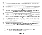
- FIG. 6 is a flow chart 600 of the operation of an offset calculation based load compensation system on a part positioner.
- a target part is loaded and secured on the part holding assembly of the part positioner.
- the shoulder drive is used to drive the part holding assembly combined with the target part.
- the torque applied to the shoulder drive during the drive in step 604 is measured as a function of power supplied to the rotational shoulder drive.
- the power delivered to the shoulder drive may be correlated to the electrical current draw of the shoulder drive during the driving for a fixed voltage motor.
- the updated position for the counter weight(s) to balance the total combined load of the part, part holding assembly, and counter weight(s) is calculated as a function the torque measured in step 606 (see also the disclosure with respect to FIG. 2 ).
- the combined load includes the counter weight(s), beam(s), and column(s) of the part holding assembly plus the load of the target part.
- the counter weight pack(s) are adjusted using the linear actuator back and forth (i.e., up and down when the column is in the vertical position) along the guide rails on the column to the updated position calculated in step 608 in order to balance the combined load with respect to the shoulder drive rotational axis.
- the counter weight pack(s) position on the column(s) is adjusted to make the combined load offset approach zero.
- the torque measurement is repeated by driving the part holding assembly combined with the target part again and measuring the torque to verify that the combined load is balanced.
- FIG. 7 is a flow chart of the operation of an empirical feedback load compensation system on a part positioner.
- a target part is loaded and secured on the part holding assembly of the part positioner to create a combined load of the part and part holding assembly.
- the part holding system holds the rotational drive of the part positioner such that the rotational drive must resist a torque supplied by gravitational force of the combined load.
- the counter weight pack (or packs) is moved in predetermined direction at a predetermined speed along the length of the column.
- the torque applied to the rotational (i.e., shoulder) drive is measured as a function of power delivered to the rotational drive while the counter weight packs are moving.
- torque may be effectively measured using measurements of values that are proportional to the actual torque.
- the power delivered to the rotational drive may be measured and used directly to compare one torque measurement to another torque measurement since the power used is directly proportional to the torque applied for many systems.
- the current drawn by the rotational drive may be used in a similar case in a fixed voltage system. Other measurements that are directly proportional to the applied torque may also be used (e.g., voltage in a fixed current system, albeit a rarely encountered system).
- the system checks to see if the torque is increasing.
- Step 714 checks to see if the measured torque has reversed direction (i.e., reversed the torque direction of rotation). If a reversal of the torque direction is detected 728 , the system may reverse the direction and slow down the movement speed of the counter weight packs at step 716 . After step 716 , the system returns to step 708 . Performing steps 714 and 716 are optional if increasing the accuracy of the counter weight placement is desired.
- the counter weight packs By reversing direction and slowing the speed of movement of the counterweight packs, the counter weight packs will go back over the point of inflection between the torque rotation directions at a slower speed, permitting the system to place the counter weight pack closer to the exact inflection point.
- the exact inflection point is the point of optimal balance which also is the location of the minimum torque applied to the rotational drive. Theoretically, the torque should be zero at the inflection point, but in real world systems the system may have losses, friction or other issues that do not permit a zero torque measurement (also may be measured as applied power and/or current to the rotational drive).
- step 720 the system checks the measured torque to ensure that the torque is still decreasing and has not reached a substantially zero value and has not detected an inflection point in the torque rotational direction. If the torque is still decreasing and is not zero or at an inflection point 732 , the system returns to step 708 . If the measured torque is substantially zero or an inflection point in the rotational direction of the torque is detected 734 , then the system stops and holds the counter weight pack in place at the point of the substantial zero or inflection point measurement. Further, if the torque is no longer decreasing 734 , the counter weight pack may have reached the end of the length of column and the effective counter force that may be applied by the counter weight has been reached (i.e., the minimum torque achievable by the system).
- any part positioner with a rotational drive rotating a part and the part holding assembly about the rotational axis of the rotational drive may be utilized. Affixing a column to the part holding assembly that is perpendicular to the rotational axis permits a counter weight pack to attached and moved along a length of the column such that the counter weight pack may counter act the rotational forces applied by rotating the part and part holding assembly. Further, one skilled in the art will recognize that more than one column may be utilized to provide a structure for multiple counter weight packs. Also, one skilled in the art will recognize that multiple weight packs may be used on the same column.
- FIG. 8 is a flow chart 800 of the operation of a step based empirical feedback load compensation system on a part positioner.
- step-based it is intended to denote that the counter weight pack is moved in incremental steps for each measurement.
- a target part is loaded and secured on the part holding assembly of the part positioner.
- a counter weight balance movement direction for moving the counter weight packs along the guide rails on the column is determined such that moving the counter weight pack(s) in the counter weight balance movement direction will reduce the torque applied by the shoulder drive to rotate the part holding assembly combined with loaded target part.
- One means to select the counter weight balance movement direction is to move the counter weight pack(s) to either end of the column and then to set the counter weight balance direction to move the counter weight pack(s) in the direction toward the opposite end of the column.
- a second means would utilize two torque measurements at the rotational shoulder drive to determine the correct counter weight balance movement direction and is described in greater detail in the disclosure with respect to FIG. 9 .
- the shoulder drive is used to drive the part holding assembly combined with the target part in order to establish a base measurement.
- the torque applied to the shoulder drive during the base rotation in step 806 is measured as a function of power supplied to the rotational shoulder at step 806 .
- the power delivered to the shoulder drive may be correlated to the electrical current draw of the shoulder drive during the driving for a fixed voltage motor.
- the counter weight pack(s) is moved a predetermined distance along the column length in the counter weight balance movement direction determined at step 804 .
- the shoulder drive is used to drive the part holding assembly combined with the target part in order to establish a test measurement.
- the torque applied to the shoulder drive during the test rotation in step 812 is measured as a function of power supplied to the rotational shoulder drive to at step 812 .
- step 816 if the test torque measurement is less than the base torque measurement (i.e., the torque is being reduced by the counter weight movement), then the base torque measurement value is set equal to the test torque measurement value and steps 810 - 816 , making up a counter weight adjustment sub-process 820 , are repeated.
- step 816 if the test torque measurement is not less than the base torque measurement (i.e., the torque is being increased by the counter weight movement), then the counter weight pack(s) has crossed the optimal location for the counter weight pack(s) in the last counter weight pack(s) movement (at step 810 ) and the counter weight adjustment sub-process is ended.
- the predetermined distance may be reduced, the counter weight balance direction toggled to the opposite direction along the column length, the base torque value set equal to the test torque value, and the counter weight adjustment process 820 may be restarted using the reduced predetermined distance in order to increase the accuracy (i.e., decrease the margin of error) of the final counter weight location.
- the counter weight balance movement direction is toggled to the opposite direction because the last movement of the counter weight pack(s) at step 810 caused the counter weight pack to go past the optimal counter weight pack(s) location.
- the base torque value is set equal to the test torque value in order to establish a base measurement to compare the next test measurement to after the counter weight pack(s) is moved again in the next iteration of the counter weight adjustment process 820 .
- Step 818 permits a load compensation system to narrow down the counter weight pack(s) final location to a position within a reasonable margin of error of the theoretical optimum location for the counter weight pack(s).
- the counter weight pack(s) may be quickly moved to a point near the theoretical optimum position and then fine tuned by performing the same process 820 with a reduced predetermined distance. Multiple stages of predetermined distances may be used to gradually narrow down the final location for the counter weight pack while keeping the number of test rotations to a minimum.
- an initial predetermined distance may be 24 inches, which will permit the counter weight pack(s) to be moved to within 24 inches of the theoretical optimum location in a few move cycles.
- the predetermined distance may then be reduced to 6 inches, permitting the counter weight pack(s) to be moved to within 6 inches of the theoretical optimum location in a few more cycles (i.e., no more than 4 move cycles once the counter weight pack is within 24 inches of the optimum location).
- the predetermined distance may be reduced again to 1 inch, permitting the counter weight pack(s) to be moved to within 1 inch of the theoretical optimum in a few more move cycles (i.e., no more than 6 move cycles once the counter weight pack is within 6 inches of the optimum location).
- a potential error condition may be encountered when the counter weight pack(s) does not provide sufficient counter weight to balance the combined load of the target part combined with the part holding assembly without further extending the column length to create a longer moment arm. Since extending the column length may be impractical due to the rotational work envelope of the part positioner system, it would likely be more practical to add additional weight to the counter weight pack(s) to resolve the error condition.
- Another error condition may occur if there is not a measurable difference in torque values between the base and the test torque measurements. Having no measurable torque difference may indicate that the counter weight is not heavy enough to properly affect the center of gravity and/or the predetermined distance that the counter weight pack(s) is moved is too small to permit a measurable change in the torque value between counter weight pack(s) moves.
- FIG. 9 is a flow chart 900 of the operation of a step based empirical feedback load compensation system on a part positioner where the counter weight balance movement direction is determined by rotating the combined load with the shoulder drive.
- the flow chart 900 of FIG. 9 follows much the same progression as the flow chart 800 of FIG. 8 , except that the determination of the counter weight balance movement direction of step 804 is laid out in further detail for an embodiment that determines the counter weight balance movement direction by driving the target part and part holding assembly combined load with the rotational shoulder drive.
- a target part is loaded and secured on the part holding assembly of the part positioner.
- the shoulder drive is used to drive the part holding assembly combined with the target part in order to establish a reference measurement.
- the torque applied to the shoulder drive during the reference driving in step 904 is measured as a function of power supplied to the rotational shoulder drive at step 904 .
- the counter weight pack(s) is moved a predetermined distance along the column length in an arbitrary direction (i.e., either direction) along the length of the column. The direction the counter weight pack(s) is moved is not important since the movement is being performed to determine the proper direction of movement for the counter weight pack(s) to reduce the torque applied by the shoulder drive for use in the feedback counter weight adjustment sub-process 926 .
- the shoulder drive is used to drive the part holding assembly combined with the target part in order to establish a base measurement.
- the torque applied to the shoulder drive during the base rotation in step 910 is measured as a function of power supplied to the rotational shoulder drive at step 910 .
- the counter weight balance movement direction is set equal to the arbitrary direction of step 908 . If the base torque is not less than the reference torque then the counter weight balance movement direction is set to the opposite direction of the arbitrary direction of step 908 .
- the counter weight pack(s) is moved a predetermined distance along the column length in the counter weight balance movement direction set at step 914 .
- the shoulder drive is used to drive the part holding assembly combined with the target part in order to establish a test measurement.
- the torque applied to the shoulder drive during the test driving in step 918 is measured as a function of power supplied to the rotational shoulder drive at step 918 .
- the base torque measurement value is set equal to the test torque measurement value and steps 916 - 922 , making up a counter weight adjustment sub-process 926 , are repeated.
- step 922 if the test torque measurement is not less than the base torque measurement (i.e., the torque is being increased by the counter weight movement), then the counter weight pack(s) has crossed the optimal location for the counter weight pack(s) in the last counter weight pack(s) movement (at step 916 ) and the counter weight adjustment sub-process is ended.
- the predetermined distance may be reduced, the counter weight balance direction toggled to the opposite direction along the column length, the base torque value set equal to the test torque value, and the counter weight adjustment process 926 may be restarted using the reduced predetermined distance in order to increase the accuracy of the final counter weight location.
- the counter weight balance movement direction is toggled to the opposite direction because the last movement of the counter weight pack(s) at step 916 caused the counter weight pack to go past the optimal counter weight pack(s) location.
- the base torque value is set equal to the test torque value in order to establish a base measurement to compare the next test measurement to after the counter weight pack(s) is moved again in the next iteration of the counter weight adjustment process 926 .
- Other considerations for step 924 are discussed in relation to step 818 as discussed in disclosure with respect to FIG. 8 .
- FIG. 10 is a flow chart of the operation to adjust for a part that is independently rotated on the part holding platter.
- a target part is loaded and secured on the part holding assembly of the part positioner to create a combined load of the part and part holding assembly.
- the part holding assembly has a rotational platter that holds the part.
- the rotational platter has an axis of rotation that is substantially perpendicular to the axis of rotation of the shoulder (i.e., main) rotational drive.
- the system determines a first location for the counter weight pack(s) on the column(s) that is optimized for balance of the part at a particular rotation of the platter using one of the embodiments of the invention disclosed herein.
- the platter is at least partially rotated such that the part is at a different rotation than for step 1004 .
- the system determines a second location for the counter weight pack(s) on the column(s) that is optimized for balance of the part at the second rotation of the platter using one of the embodiments of the invention disclosed herein.
- the robot and part positioning system is operated to work on the part with the counter weights at the second location. Note that the system may also operate with the counter weights at the first location prior to at least partially rotating the part on the rotational platter. In other words, the system may update the counterweight placement as needed to accommodate different rotations of the part on the platter.
- FIG. 11 is a flow chart of the operation to adjust to an average location for the counter weights for various rotations of the platter holding the target part.
- a target part is loaded and secured on the part holding assembly of the part positioner to create a combined load of the part and part holding assembly.
- the part holding assembly has a rotational platter that holds the part.
- the rotational platter has an axis of rotation that is substantially perpendicular to the axis of rotation of the shoulder (i.e., main) rotational drive.
- the system determines a first location for the counter weight pack(s) on the column(s) that is optimized for balance of the part at a particular rotation of the platter using one of the embodiments of the invention disclosed herein.
- the system records the first location of the counter weight pack(s) on the column(s).
- the platter is at least partially rotated such that the part is at a different rotation than for step 1104 or previous step 1108 s .
- the system determines an additional/new location for the counter weight pack(s) on the column(s) that is optimized for balance of the part at the new rotation of the platter using one of the embodiments of the invention disclosed herein.
- new rotations of the part on the platter are processed through steps 1108 - 1112 as desired to record sufficient data to average.
- the system averages the recorded first and additional/supplementary counter weight pack locations.
- the system moves the counter weight pack(s) to the average position of the counter weight pack.
- the robot and part positioning system is operated to work on the part with the counter weights at the average location. While the average position may not be optimal for the part at any particular platter rotation, the average position represents a good compromise between the various platter rotations so that recalibrating the count weight pack location after each time the platter is rotated may not be necessary.
- Various embodiments may mount the part positioner system on surfaces other than the floor in contrast to the various floor mounted part positioners described in the figures.
- a part positioner may be mounted on a wall or any other surface capable of supporting the weight and applied forces exerted by the part positioner system if desired.
- Various embodiments may also be used to actively adjust the counter weight pack(s) location while a part is being positioned for work operations by the robot using torque measurements obtained from shoulder drive rotations used to position the target part to have operations performed by the robot. Hence, an optimum balance may be maintained even as the combined load offset changes due to the work being performed on the target part.
- Various embodiments may perform calculations and communicate counter weight movement instructions using a computer system running software to perform the necessary functions. Alternatively, various embodiments may perform calculations and communicate counter weight movement instructions using a dedicated electronic controller with sufficient processing power and memory to perform the necessary functions.
- the various embodiments may provide numerous benefits for a part positioner system. Since the counter weight pack(s) may be quickly and easily moved to accommodate different target parts, a single part positioner and robot system may be used for a variety of target parts without the need to perform extensive calculations to find a new center of gravity of the combined load and without the time and labor required to physically adjust the size and location of the counter weight pack(s) on the column by manually unfastening (i.e., unbolting) the counter weight pack(s), physically moving the counter weight pack to a new location, and fastening (i.e., bolting) the counter weight pack(s) in place.
- Various embodiments may be particularly well suited for welding applications that require extensive part positioning needs for very large and awkward target parts.
- a welding application may have included a significant change in the combined load offset due to the welding procedures.
- a welding application may benefit from a recalibration of the counter weight pack(s) while the target part is still being operated on by the robotic welder as is possible through various embodiments.
- various embodiments may expand the range of target parts that may be loaded on a particular part positioner system. The expanded range is particularly evident for larger target part loads as the torque requirements for the shoulder drive are reduced due to the combined load balance improvements.
- cost savings may be achieved since a smaller part positioning gear set up may be utilized for with better balanced load combined load of an embodiment.
- the operation of the rotational shoulder drive may also be improved as the speed and acceleration of the drive may improve due to the improvement in the combined load balance. Further, the wear and tear on the rotational shoulder drive is reduced resulting in longer part positioner system life.
- Embodiments may provide the control and management functions detailed herein via an application operating on a computer system (or other electronic devices).
- Embodiments may be provided as a computer program product which may include a computer-readable, or machine-readable, medium having stored thereon instructions which may be used to program/operate a computer (or other electronic devices) or computer system to perform a process or processes in accordance with the present invention.
- the computer-readable medium may include, but is not limited to, hard disk drives, floppy diskettes, optical disks, Compact Disc Read-Only Memories (CD-ROMs), Digital Versatile Disc ROMS (DVD-ROMs), Universal Serial Bus (USB) memory sticks, magneto-optical disks, ROMs, random access memories (RAMs), Erasable Programmable ROMs (EPROMs), Electrically Erasable Programmable ROMs (EEPROMs), magnetic optical cards, flash memory, or other types of media/machine-readable medium suitable for storing electronic instructions.
- the computer program instructions may reside and operate on a single computer/electronic device or various portions may be spread over multiple computers/devices that comprise a computer system.
- embodiments may also be downloaded as a computer program product, wherein the program may be transferred from a remote computer to a requesting computer by way of data signals embodied in a carrier wave or other propagation medium via a communication link (e.g., a modem or network connection, including both wired/cabled and wireless connections).
- a communication link e.g., a modem or network connection, including both wired/cabled and wireless connections.
Landscapes
- Engineering & Computer Science (AREA)
- Mechanical Engineering (AREA)
- Manipulator (AREA)
Abstract
Description
τ=rF Eq. 1
Torque may also be measured in terms of the angular speed of rotation and the power applied to achieve the angular speed of rotation as in Eq. 2.
To calculate an updated distance (i.e., position) (D2′) 210 from the center of rotation (COR) 214 for the counter weight (CW) 202, an embodiment may obtain a torque measurement for the system and then calculate the updated distance (D2′) 210 based on the torque calculation. For an embodiment that measures the torque based on the proportional relationship between power and/or current supplied to the shoulder drive to hold the part holding assembly plus the part in place against the
Perpendicular_Force=W sin(Θ) Eq. 3
In accordance with Eq. 1 and Eq. 3, the initial net torque (τinit) applied by the initial conditions may be represented by Eq. 4.
τinit =D 1 W 1 sin(Θ)−D 2 W 2 sin(Θ) Eq. 4
The torque (τ) with the counter weight (CW) 202 at the initial distance (D1) may be measured, as described above, as a function of the power delivered to drive the shoulder drive to hold the part holding assembly against gravitational forces and/or as a function of the power delivered to drive the shoulder drive at an angular speed via Eq. 2. With the initial torque (τinit) known, the system of Eq. 4 may be solved for the unknown distance (D1) 216 from the center of
Once the
As understood by a person skilled in the art, other methodologies may be used to calculate the updated position (D2′) 210 of the counter weight (CW) 202 from the center of
Claims (65)
Priority Applications (1)
| Application Number | Priority Date | Filing Date | Title |
|---|---|---|---|
| US12/422,756 US8099184B2 (en) | 2009-04-13 | 2009-04-13 | Load compensation for robotic applications |
Applications Claiming Priority (1)
| Application Number | Priority Date | Filing Date | Title |
|---|---|---|---|
| US12/422,756 US8099184B2 (en) | 2009-04-13 | 2009-04-13 | Load compensation for robotic applications |
Publications (2)
| Publication Number | Publication Date |
|---|---|
| US20100262275A1 US20100262275A1 (en) | 2010-10-14 |
| US8099184B2 true US8099184B2 (en) | 2012-01-17 |
Family
ID=42935011
Family Applications (1)
| Application Number | Title | Priority Date | Filing Date |
|---|---|---|---|
| US12/422,756 Active 2030-07-28 US8099184B2 (en) | 2009-04-13 | 2009-04-13 | Load compensation for robotic applications |
Country Status (1)
| Country | Link |
|---|---|
| US (1) | US8099184B2 (en) |
Cited By (9)
| Publication number | Priority date | Publication date | Assignee | Title |
|---|---|---|---|---|
| CN102736554A (en) * | 2012-07-05 | 2012-10-17 | 浙江大学 | Method for designing heavy loading three-coordinate numerical control positioner based on rigidity matching |
| CN102794592A (en) * | 2012-08-31 | 2012-11-28 | 中建钢构江苏有限公司 | Adjustable automatic displacement device for steel member |
| CN104849031A (en) * | 2015-04-27 | 2015-08-19 | 江西洪都航空工业集团有限责任公司 | Bidirectional loading module |
| US20150251883A1 (en) * | 2014-03-10 | 2015-09-10 | Arnaldo Miranda | Automotive Hydraulic Tilt Lift Assembly and Related Methods |
| CN105666159A (en) * | 2016-03-31 | 2016-06-15 | 泉州市华茂机械设备有限公司 | Roller side cover processing turning table |
| CN105710587A (en) * | 2016-04-20 | 2016-06-29 | 枣庄矿业(集团)有限责任公司柴里煤矿 | Butt welding rotating frame for I-shaped steel beam |
| US9844841B2 (en) | 2015-05-08 | 2017-12-19 | Lincoln Global, Inc. | Drop center positioner with multiple rotate modules |
| US20180326531A1 (en) * | 2016-06-02 | 2018-11-15 | Kaijo Corporation | Bonding apparatus, bonding method and bonding control program |
| US10394969B2 (en) * | 2014-02-07 | 2019-08-27 | Canon Kabushiki Kaisha | Dynamics calculation method, program and recording medium |
Families Citing this family (15)
| Publication number | Priority date | Publication date | Assignee | Title |
|---|---|---|---|---|
| CA2796088C (en) * | 2010-04-09 | 2018-02-06 | Ekso Bionics | Exoskeleton load handling system and method of use |
| KR101165531B1 (en) * | 2010-08-27 | 2012-07-16 | 하나로테크 주식회사 | Swing ring plate manufacturing device and method using it |
| US9630284B2 (en) * | 2012-07-12 | 2017-04-25 | Lincoln Global, Inc. | Configurable welding table and force indicating clamp |
| CN103029849B (en) * | 2012-12-12 | 2014-12-10 | 江西洪都航空工业集团有限责任公司 | Airplane overturn testing device and airplane overturn testing method |
| JP6505558B2 (en) * | 2015-09-15 | 2019-04-24 | 津田駒工業株式会社 | Inclined indexing device |
| US10328538B2 (en) * | 2017-07-20 | 2019-06-25 | Gary Tsui | Rotary positioner with outriggers |
| JP6564437B2 (en) | 2017-09-06 | 2019-08-21 | ファナック株式会社 | Rotary table system |
| CN108408079A (en) * | 2018-03-19 | 2018-08-17 | 西安睿诺新能源有限公司 | A kind of unilateral side counterweight lifting ground well |
| CN109911241B (en) * | 2019-03-20 | 2022-06-14 | 成都飞机工业(集团)有限责任公司 | Seven-degree polynomial-based multi-section automatic posture adjusting method |
| JP7227073B2 (en) * | 2019-05-23 | 2023-02-21 | ファナック株式会社 | Workpiece rotating device and robot system |
| CN112158357B (en) * | 2020-08-28 | 2021-08-03 | 成都飞机工业(集团)有限责任公司 | Device and method for measuring deviation between thrust line and gravity center of unmanned aerial vehicle booster rocket |
| JP7730534B2 (en) * | 2021-06-14 | 2025-08-28 | テクノダイナミックス株式会社 | Tilting Rotating Table Device |
| IT202100023888A1 (en) * | 2021-09-16 | 2023-03-16 | Emanuel S R L | ERGONOMIC POSITIONER |
| CN116571941A (en) * | 2023-05-30 | 2023-08-11 | 江西核威环保科技有限公司 | A high-efficiency solid-liquid separation equipment parts processing equipment |
| CN117970892B (en) * | 2024-03-29 | 2024-07-09 | 合肥焕智科技有限公司 | Control method and device of conveying system |
Citations (50)
| Publication number | Priority date | Publication date | Assignee | Title |
|---|---|---|---|---|
| US2348062A (en) * | 1942-12-23 | 1944-05-02 | Ransome Machinery Company | Welding positioner and manipulator |
| US2729883A (en) * | 1953-02-25 | 1956-01-10 | Worthington Corp | Positioner for welding or other manufacturing operation |
| US3239209A (en) * | 1964-04-21 | 1966-03-08 | Stephen P Kucka | Welding work positioner adapter for nonlinear workpieces such as elbows and the like |
| US3499549A (en) * | 1968-07-19 | 1970-03-10 | Eddie B Wagner | Beam weldment positioner |
| US3575301A (en) * | 1968-01-02 | 1971-04-20 | Ibm | Manipulator |
| US3595558A (en) * | 1968-12-23 | 1971-07-27 | Reading Co | Positioner for objects |
| US3878951A (en) * | 1974-04-22 | 1975-04-22 | Eddie B Wagner | Work positioner |
| JPS5732896A (en) * | 1980-08-05 | 1982-02-22 | Mitsubishi Heavy Ind Ltd | Positioner for welding |
| US4455838A (en) * | 1981-02-16 | 1984-06-26 | Toyama Machine Works, Ltd. | Control device for a balancing apparatus |
| US4517853A (en) * | 1981-02-16 | 1985-05-21 | Toyama Machine Works, Limited | Balancing device |
| US4527942A (en) * | 1982-08-25 | 1985-07-09 | Intest Corporation | Electronic test head positioner for test systems |
| US4541062A (en) * | 1983-04-26 | 1985-09-10 | Kabushiki Kaisha Kobe Seiko Sho | Method of interlockingly controlling a robot and positioner |
| JPS6120667A (en) * | 1984-07-06 | 1986-01-29 | Hitachi Ltd | Welding torch speed control method |
| US4641820A (en) * | 1985-06-07 | 1987-02-10 | Deere & Company | Weld fixture mounting |
| US4713873A (en) * | 1985-06-07 | 1987-12-22 | Deere & Company | Weld fixture mounting method |
| JPS63154296A (en) * | 1986-12-17 | 1988-06-27 | Toyo Mach & Metal Co Ltd | Positioner workpiece mounting device for welding robots, etc. |
| JPS6453777A (en) * | 1987-08-24 | 1989-03-01 | Hitachi Ltd | Automatic welding equipment |
| JPH01101279A (en) * | 1987-10-13 | 1989-04-19 | Honda Motor Co Ltd | Component positioner of automobile body welding machine |
| US4890579A (en) * | 1985-10-17 | 1990-01-02 | The United States Of America As Represented By The Secretary Of The Air Force | Timed primate roto-positioner |
| US4892993A (en) * | 1988-05-19 | 1990-01-09 | Aluminum Company Of America | Welding system for hollow thin walled members |
| JPH035097A (en) * | 1989-06-01 | 1991-01-10 | Shin Meiwa Ind Co Ltd | Positioner for welding robots |
| JPH05112901A (en) * | 1991-10-04 | 1993-05-07 | Magnet Bahn Gmbh | Travelling path of trough type support structure made of steel for magnetic track car and method and device for manufacturing support structure made of steel of said travelling path |
| JPH05177391A (en) * | 1991-12-28 | 1993-07-20 | Oyamada Mokkosho:Kk | Positioner for welding |
| JPH05228632A (en) * | 1992-02-24 | 1993-09-07 | Shin Meiwa Ind Co Ltd | Welding robot device capable of welding different kinds of works |
| JPH05318120A (en) * | 1992-05-14 | 1993-12-03 | Nishiyama Kogyosho:Kk | Automatic welding positioner |
| JPH05318109A (en) * | 1992-05-25 | 1993-12-03 | Kobe Steel Ltd | Device for welding steel frame structure |
| US5313695A (en) * | 1989-03-28 | 1994-05-24 | Renault Automation | Process and device for body assembly with lateral tools that can be interpositioned |
| JPH06170531A (en) * | 1992-10-30 | 1994-06-21 | Komatsu Ltd | Automatic welding equipment for steel joints |
| US5325305A (en) * | 1992-07-24 | 1994-06-28 | The Boeing Company | Automated setup verification system |
| JPH06344142A (en) * | 1993-06-10 | 1994-12-20 | Mitsubishi Nagasaki Mach Co Ltd | Tube-inside peripheral surface build-up welding equipment and welding torch |
| JPH07164188A (en) * | 1993-12-10 | 1995-06-27 | Tomoe Giken:Kk | Method and apparatus for reversing columnar object |
| JPH07310436A (en) * | 1994-05-18 | 1995-11-28 | Koei Kisetsu Kogyo Kk | Steel-frame material positioner |
| JPH0825088A (en) * | 1994-07-19 | 1996-01-30 | Mitsubishi Electric Corp | Positioner tilting device for welding robot |
| US5873569A (en) * | 1994-01-21 | 1999-02-23 | Genesis Systems Group | Workpiece positioner |
| US6053280A (en) * | 1998-03-17 | 2000-04-25 | Wall Walker, Llc | Hanging scaffold support |
| JP2000254778A (en) * | 1999-03-10 | 2000-09-19 | Nkk Corp | Column ring welding equipment |
| JP2000263291A (en) * | 1999-03-16 | 2000-09-26 | Fujimi Tekko Kk | Positioner for welding |
| JP2000288787A (en) * | 1999-04-09 | 2000-10-17 | Komatsu Engineering Kk | Welding jig of column through column of structural steel-work |
| US6281474B1 (en) * | 1999-08-17 | 2001-08-28 | Motoman, Inc. | X-beam positioner |
| US6305678B1 (en) * | 2000-06-02 | 2001-10-23 | Hammersmith Mfg. & Sales, Inc. | Welder positioner |
| US6347733B1 (en) * | 2000-04-04 | 2002-02-19 | Hickey, Ii Edward J. | Worker piece positioner for use with industrial robot |
| US20030141155A1 (en) * | 2000-02-23 | 2003-07-31 | Anders Daneryd | Industrial robot with an actuated brake system, which cooperate with the robot's control system |
| US6606531B1 (en) * | 2002-02-07 | 2003-08-12 | Trumpf, Inc. | Sheet material loader/unloader for machine tools |
| US20050129495A1 (en) * | 2003-12-16 | 2005-06-16 | Abb Ab | Industrial robot |
| EP1731259A1 (en) * | 2005-06-09 | 2006-12-13 | Fanuc Ltd | Workpiece positioner for arc welding and arc welding robot system having the positioner |
| US7172376B1 (en) * | 2006-01-24 | 2007-02-06 | Progressive Systems, Inc. | Workpiece positioner |
| US20080246204A1 (en) * | 2004-07-29 | 2008-10-09 | Elliott Company | Positioning Device for the Fabrication of Compressor Impellers |
| US20110084052A1 (en) * | 2009-10-08 | 2011-04-14 | Lincoln Global, Inc. | Adjustable span ferris wheel positioner |
| US20110174793A1 (en) * | 2010-01-19 | 2011-07-21 | Kabushiki Kaisha Yaskawa Denki | Robot system having positioner |
| US20110186615A1 (en) * | 2010-02-02 | 2011-08-04 | Gatlin Robert W | Ring Gear Based Welding System |
-
2009
- 2009-04-13 US US12/422,756 patent/US8099184B2/en active Active
Patent Citations (52)
| Publication number | Priority date | Publication date | Assignee | Title |
|---|---|---|---|---|
| US2348062A (en) * | 1942-12-23 | 1944-05-02 | Ransome Machinery Company | Welding positioner and manipulator |
| US2729883A (en) * | 1953-02-25 | 1956-01-10 | Worthington Corp | Positioner for welding or other manufacturing operation |
| US3239209A (en) * | 1964-04-21 | 1966-03-08 | Stephen P Kucka | Welding work positioner adapter for nonlinear workpieces such as elbows and the like |
| US3575301A (en) * | 1968-01-02 | 1971-04-20 | Ibm | Manipulator |
| US3499549A (en) * | 1968-07-19 | 1970-03-10 | Eddie B Wagner | Beam weldment positioner |
| US3595558A (en) * | 1968-12-23 | 1971-07-27 | Reading Co | Positioner for objects |
| US3878951A (en) * | 1974-04-22 | 1975-04-22 | Eddie B Wagner | Work positioner |
| JPS5732896A (en) * | 1980-08-05 | 1982-02-22 | Mitsubishi Heavy Ind Ltd | Positioner for welding |
| US4455838A (en) * | 1981-02-16 | 1984-06-26 | Toyama Machine Works, Ltd. | Control device for a balancing apparatus |
| US4517853A (en) * | 1981-02-16 | 1985-05-21 | Toyama Machine Works, Limited | Balancing device |
| US4527942A (en) * | 1982-08-25 | 1985-07-09 | Intest Corporation | Electronic test head positioner for test systems |
| US4541062A (en) * | 1983-04-26 | 1985-09-10 | Kabushiki Kaisha Kobe Seiko Sho | Method of interlockingly controlling a robot and positioner |
| JPS6120667A (en) * | 1984-07-06 | 1986-01-29 | Hitachi Ltd | Welding torch speed control method |
| US4641820A (en) * | 1985-06-07 | 1987-02-10 | Deere & Company | Weld fixture mounting |
| US4713873A (en) * | 1985-06-07 | 1987-12-22 | Deere & Company | Weld fixture mounting method |
| US4890579A (en) * | 1985-10-17 | 1990-01-02 | The United States Of America As Represented By The Secretary Of The Air Force | Timed primate roto-positioner |
| JPS63154296A (en) * | 1986-12-17 | 1988-06-27 | Toyo Mach & Metal Co Ltd | Positioner workpiece mounting device for welding robots, etc. |
| JPS6453777A (en) * | 1987-08-24 | 1989-03-01 | Hitachi Ltd | Automatic welding equipment |
| JPH01101279A (en) * | 1987-10-13 | 1989-04-19 | Honda Motor Co Ltd | Component positioner of automobile body welding machine |
| US4892993A (en) * | 1988-05-19 | 1990-01-09 | Aluminum Company Of America | Welding system for hollow thin walled members |
| US5313695A (en) * | 1989-03-28 | 1994-05-24 | Renault Automation | Process and device for body assembly with lateral tools that can be interpositioned |
| JPH035097A (en) * | 1989-06-01 | 1991-01-10 | Shin Meiwa Ind Co Ltd | Positioner for welding robots |
| JPH05112901A (en) * | 1991-10-04 | 1993-05-07 | Magnet Bahn Gmbh | Travelling path of trough type support structure made of steel for magnetic track car and method and device for manufacturing support structure made of steel of said travelling path |
| JPH05177391A (en) * | 1991-12-28 | 1993-07-20 | Oyamada Mokkosho:Kk | Positioner for welding |
| JPH05228632A (en) * | 1992-02-24 | 1993-09-07 | Shin Meiwa Ind Co Ltd | Welding robot device capable of welding different kinds of works |
| JPH05318120A (en) * | 1992-05-14 | 1993-12-03 | Nishiyama Kogyosho:Kk | Automatic welding positioner |
| JPH05318109A (en) * | 1992-05-25 | 1993-12-03 | Kobe Steel Ltd | Device for welding steel frame structure |
| US5325305A (en) * | 1992-07-24 | 1994-06-28 | The Boeing Company | Automated setup verification system |
| JPH06170531A (en) * | 1992-10-30 | 1994-06-21 | Komatsu Ltd | Automatic welding equipment for steel joints |
| JPH06344142A (en) * | 1993-06-10 | 1994-12-20 | Mitsubishi Nagasaki Mach Co Ltd | Tube-inside peripheral surface build-up welding equipment and welding torch |
| JPH07164188A (en) * | 1993-12-10 | 1995-06-27 | Tomoe Giken:Kk | Method and apparatus for reversing columnar object |
| US5873569A (en) * | 1994-01-21 | 1999-02-23 | Genesis Systems Group | Workpiece positioner |
| JPH07310436A (en) * | 1994-05-18 | 1995-11-28 | Koei Kisetsu Kogyo Kk | Steel-frame material positioner |
| JPH0825088A (en) * | 1994-07-19 | 1996-01-30 | Mitsubishi Electric Corp | Positioner tilting device for welding robot |
| US6053280A (en) * | 1998-03-17 | 2000-04-25 | Wall Walker, Llc | Hanging scaffold support |
| JP2000254778A (en) * | 1999-03-10 | 2000-09-19 | Nkk Corp | Column ring welding equipment |
| JP2000263291A (en) * | 1999-03-16 | 2000-09-26 | Fujimi Tekko Kk | Positioner for welding |
| JP2000288787A (en) * | 1999-04-09 | 2000-10-17 | Komatsu Engineering Kk | Welding jig of column through column of structural steel-work |
| US6281474B1 (en) * | 1999-08-17 | 2001-08-28 | Motoman, Inc. | X-beam positioner |
| US20030141155A1 (en) * | 2000-02-23 | 2003-07-31 | Anders Daneryd | Industrial robot with an actuated brake system, which cooperate with the robot's control system |
| US6347733B1 (en) * | 2000-04-04 | 2002-02-19 | Hickey, Ii Edward J. | Worker piece positioner for use with industrial robot |
| US6305678B1 (en) * | 2000-06-02 | 2001-10-23 | Hammersmith Mfg. & Sales, Inc. | Welder positioner |
| US6606531B1 (en) * | 2002-02-07 | 2003-08-12 | Trumpf, Inc. | Sheet material loader/unloader for machine tools |
| US20050129495A1 (en) * | 2003-12-16 | 2005-06-16 | Abb Ab | Industrial robot |
| US7300240B2 (en) * | 2003-12-16 | 2007-11-27 | Abb Ab | Industrial robot |
| US20080246204A1 (en) * | 2004-07-29 | 2008-10-09 | Elliott Company | Positioning Device for the Fabrication of Compressor Impellers |
| EP1731259A1 (en) * | 2005-06-09 | 2006-12-13 | Fanuc Ltd | Workpiece positioner for arc welding and arc welding robot system having the positioner |
| US20060278622A1 (en) * | 2005-06-09 | 2006-12-14 | Fanuc Ltd | Positioner for arc welding and arc welding robot system having the positioner |
| US7172376B1 (en) * | 2006-01-24 | 2007-02-06 | Progressive Systems, Inc. | Workpiece positioner |
| US20110084052A1 (en) * | 2009-10-08 | 2011-04-14 | Lincoln Global, Inc. | Adjustable span ferris wheel positioner |
| US20110174793A1 (en) * | 2010-01-19 | 2011-07-21 | Kabushiki Kaisha Yaskawa Denki | Robot system having positioner |
| US20110186615A1 (en) * | 2010-02-02 | 2011-08-04 | Gatlin Robert W | Ring Gear Based Welding System |
Non-Patent Citations (3)
| Title |
|---|
| Weld Plus Inc., "Weld Plus Product Details-RP309001P Koike-Aronson Robotic Welding Positioner", obtained online at www.weldplus.com/product-details on Aug. 22, 2011. * |
| Wolf Robotics, "SmartPositioners-Manual and Automated Arc Welding Positioners", 2007, Form No. 1248-2b, obtained online at www.wolfrobotics.com on Aug. 22, 2011. * |
| Wolf Robotics, "System Profie", 2007, Form No. 1081-20, obtained online at www.wolfrobotics.com on Aug. 22, 2011. * |
Cited By (13)
| Publication number | Priority date | Publication date | Assignee | Title |
|---|---|---|---|---|
| CN102736554B (en) * | 2012-07-05 | 2014-06-04 | 浙江大学 | Method for designing heavy loading three-coordinate numerical control positioner based on rigidity matching |
| CN102736554A (en) * | 2012-07-05 | 2012-10-17 | 浙江大学 | Method for designing heavy loading three-coordinate numerical control positioner based on rigidity matching |
| CN102794592A (en) * | 2012-08-31 | 2012-11-28 | 中建钢构江苏有限公司 | Adjustable automatic displacement device for steel member |
| US10394969B2 (en) * | 2014-02-07 | 2019-08-27 | Canon Kabushiki Kaisha | Dynamics calculation method, program and recording medium |
| US20150251883A1 (en) * | 2014-03-10 | 2015-09-10 | Arnaldo Miranda | Automotive Hydraulic Tilt Lift Assembly and Related Methods |
| CN104849031A (en) * | 2015-04-27 | 2015-08-19 | 江西洪都航空工业集团有限责任公司 | Bidirectional loading module |
| US9844841B2 (en) | 2015-05-08 | 2017-12-19 | Lincoln Global, Inc. | Drop center positioner with multiple rotate modules |
| CN105666159A (en) * | 2016-03-31 | 2016-06-15 | 泉州市华茂机械设备有限公司 | Roller side cover processing turning table |
| CN105666159B (en) * | 2016-03-31 | 2018-07-31 | 泉州市华茂机械设备有限公司 | Roller side cover processing turning table |
| CN105710587A (en) * | 2016-04-20 | 2016-06-29 | 枣庄矿业(集团)有限责任公司柴里煤矿 | Butt welding rotating frame for I-shaped steel beam |
| US20180326531A1 (en) * | 2016-06-02 | 2018-11-15 | Kaijo Corporation | Bonding apparatus, bonding method and bonding control program |
| US11173567B2 (en) * | 2016-06-02 | 2021-11-16 | Kaijo Corporation | Bonding apparatus with rotating bonding stage |
| US11273515B2 (en) | 2016-06-02 | 2022-03-15 | Kaijo Corporation | Bonding process with rotating bonding stage |
Also Published As
| Publication number | Publication date |
|---|---|
| US20100262275A1 (en) | 2010-10-14 |
Similar Documents
| Publication | Publication Date | Title |
|---|---|---|
| US8099184B2 (en) | Load compensation for robotic applications | |
| CN102234026B (en) | Palletizing robot | |
| US8849456B2 (en) | Robot, carriage device, and control method using inertia sensor | |
| US8838275B2 (en) | Robot and robot control method | |
| CN101132873B (en) | Methods and apparatus for manufacturing operations | |
| CN101281011B (en) | Oscillating scanning probe with constant contact force | |
| CN104837526B (en) | Proton Therapy Rack System | |
| JP5418272B2 (en) | Thermal displacement correction method and thermal displacement correction apparatus for machine tool | |
| US20080213077A1 (en) | Articulated robot | |
| US9789578B2 (en) | Counterforce mechanism and methods of operation thereof | |
| JP6501529B2 (en) | Method of processing a work using a machine tool and machine tool | |
| US10315255B2 (en) | Machine tool with an assembly configuration with a cantilevered tool | |
| CA2860736A1 (en) | Methods and apparatus for manufacturing operations | |
| KR20170132560A (en) | Machining center | |
| JP6782161B2 (en) | Machine Tools | |
| TW201832456A (en) | Workpiece conveyance control system, and motion guiding device | |
| CN114185271B (en) | Annular truss three-dimensional follow-up system and control method thereof | |
| WO2026002053A1 (en) | Deflection compensation device and agv vehicle | |
| CN105797281A (en) | Systems and methods of adjusting rotating gantry system | |
| CN110290899A (en) | positioning unit | |
| TW202120250A (en) | Method for synchronous control of gantry mechanism with online inertia matching | |
| JP2000280112A (en) | High precision processing equipment | |
| CN117262049A (en) | An automatic transfer station measurement device and a measurement method for using the device to conduct ship section docking | |
| JPS62187521A (en) | Control method for rolling reduction of roller leveling machine | |
| CN221245285U (en) | Transmission double-platform structure |
Legal Events
| Date | Code | Title | Description |
|---|---|---|---|
| AS | Assignment |
Owner name: RIMROCK AUTOMATION INC. DBA WOLF ROBOTICS, COLORAD Free format text: ASSIGNMENT OF ASSIGNORS INTEREST;ASSIGNORS:SCHOENING, JOHN;GUYMON, LANCE F.;REEL/FRAME:022594/0400 Effective date: 20090415 |
|
| STCF | Information on status: patent grant |
Free format text: PATENTED CASE |
|
| FPAY | Fee payment |
Year of fee payment: 4 |
|
| AS | Assignment |
Owner name: LINCOLN GLOBAL, INC., OHIO Free format text: ASSIGNMENT OF ASSIGNORS INTEREST;ASSIGNOR:WOLF ROBOTICS, LLC;REEL/FRAME:036809/0750 Effective date: 20151014 Owner name: LINCOLN GLOBAL, INC., OHIO Free format text: ASSIGNMENT OF ASSIGNORS INTEREST;ASSIGNOR:WOLF ROBOTICS, LLC;REEL/FRAME:036809/0822 Effective date: 20151014 |
|
| FEPP | Fee payment procedure |
Free format text: PAT HOLDER NO LONGER CLAIMS SMALL ENTITY STATUS, ENTITY STATUS SET TO UNDISCOUNTED (ORIGINAL EVENT CODE: STOL); ENTITY STATUS OF PATENT OWNER: LARGE ENTITY |
|
| AS | Assignment |
Owner name: LINCOLN GLOBAL, INC., CALIFORNIA Free format text: CORRECTIVE ASSIGNMENT TO CORRECT THE ASSIGNEE ADDRESS PREVIOUSLY RECORDED AT REEL: 036809 FRAME: 0822. ASSIGNOR(S) HEREBY CONFIRMS THE ASSIGNMENT;ASSIGNOR:WOLF ROBOTICS, LLC;REEL/FRAME:043176/0889 Effective date: 20151014 |
|
| MAFP | Maintenance fee payment |
Free format text: PAYMENT OF MAINTENANCE FEE, 8TH YEAR, LARGE ENTITY (ORIGINAL EVENT CODE: M1552); ENTITY STATUS OF PATENT OWNER: LARGE ENTITY Year of fee payment: 8 |
|
| MAFP | Maintenance fee payment |
Free format text: PAYMENT OF MAINTENANCE FEE, 12TH YEAR, LARGE ENTITY (ORIGINAL EVENT CODE: M1553); ENTITY STATUS OF PATENT OWNER: LARGE ENTITY Year of fee payment: 12 |