US809881A - Vehicle-wheel. - Google Patents
Vehicle-wheel. Download PDFInfo
- Publication number
- US809881A US809881A US24662905A US1905246629A US809881A US 809881 A US809881 A US 809881A US 24662905 A US24662905 A US 24662905A US 1905246629 A US1905246629 A US 1905246629A US 809881 A US809881 A US 809881A
- Authority
- US
- United States
- Prior art keywords
- hub
- spokes
- wheel
- spoke
- vehicle
- Prior art date
- Legal status (The legal status is an assumption and is not a legal conclusion. Google has not performed a legal analysis and makes no representation as to the accuracy of the status listed.)
- Expired - Lifetime
Links
- 238000005266 casting Methods 0.000 description 4
- 238000000034 method Methods 0.000 description 3
- 238000010276 construction Methods 0.000 description 2
- 244000286663 Ficus elastica Species 0.000 description 1
- 240000001973 Ficus microcarpa Species 0.000 description 1
- RRHGJUQNOFWUDK-UHFFFAOYSA-N Isoprene Chemical compound CC(=C)C=C RRHGJUQNOFWUDK-UHFFFAOYSA-N 0.000 description 1
- 239000000835 fiber Substances 0.000 description 1
- 238000007373 indentation Methods 0.000 description 1
- 239000002184 metal Substances 0.000 description 1
- 230000004048 modification Effects 0.000 description 1
- 238000012986 modification Methods 0.000 description 1
- 229920001195 polyisoprene Polymers 0.000 description 1
Images

Classifications
-
- B—PERFORMING OPERATIONS; TRANSPORTING
- B60—VEHICLES IN GENERAL
- B60B—VEHICLE WHEELS; CASTORS; AXLES FOR WHEELS OR CASTORS; INCREASING WHEEL ADHESION
- B60B1/00—Spoked wheels; Spokes thereof
Definitions
- This invention which relates to the construction of wheels, has special reference to the hub of what is known in the trade as artillery-pattern wheels, and has for its object'to tighten up the tire and miterd ends of the spokes without the necessity of removing these from the wheel, which is at present the case.
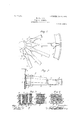
- Figure l is a view, partly in section and partly in elevation, of the hub and tire of a wheel embodying my invention.
- Fig. 2 is a longitudinal elevation of the same, partly in section.
- Fig. 3 illustrates sections taken through the hub on the lines s t and 'u w
- Fig. 4 is a section illustrating an alternative method, taken through the hub of an ordinary straight-spoke wheel.
- Fig. 5 is a similar view to Fig. 1, but with the hub in elevation.
- Fig. 6 is a longitudinal section of the same.
- Figs. 7 and 8 are sections taken through the hub on the lines w :c and y z, respectively, of Fig. 5.
- the hub a consists of a malleable casting constructed in the manner shown and comprises a series of wedge-shaped pockets or receptacles Z) for the reception of the ends of the spokes c.
- a piece of india-rubber fiber or other elastic or non-elastic pecking d as seen more particularly in Figs. 3, 7, and 8.
- the hub is embraced laterally on either side by two separate ianges ej
- the said flanges are held in position by bolts g, passing transversely through the body of the said spokes c.
- FIG. 5 to 8 illustrate the method of dispensing with the partition-walls b', which form the wedge-shaped pockets or receptacles b.
- the ends of the spokes c are formed with a right angle or curved eX- tension, as seen in Fig. 6, and with a double miter or taper whose surfaces iit close together, as seen in Fig. 7, and in such manner that by tightening up the nave-bolts g after withdrawing suflicient of the liber packingsections d the spokes will be laterally extended or pressed out toward the felly, after the manner of the arrangement illustrated in Figs. 1 to 4.
- each spoke is provided with a V-shapcd projection Z on one side and with a V-shaped recess or indentation Z on the other side. Each projection Z engages with the recess Z of the adjacent spoke.
- I claim- In a wheel, the combination of a hub provided with a plurality of radial wedge-shaped pockets having inclined bottoni surfaces, flanges surrounding the hub and forming the sides of said pockets, a spoke in each of said pockets, packing-pieces interposed Valternately between the sides of the spokes and the fianges, and means forsecuring the flanges together.
Landscapes
- Engineering & Computer Science (AREA)
- Mechanical Engineering (AREA)
- Motorcycle And Bicycle Frame (AREA)
Description
PATENTED JAN, 9
W. WRIGHT.
VEHICLE WHEEL.
APPLICATION FILED rBB.2o,19o5.
2 SHEETS-SHEET 1.
No. 809,881. PATENTED JAN. 9, 1906. W. WRIGHT.
VEHICLE WHEEL.
APPLICATION FILED FEB.20.1905.
2 SHEETS-SHEET 2.
'narran sfrarns Parana orifice.
IVALTER WIRIGHT, OF GLASGOW, SCOTLAND, ASSIGNOR TO S. STEVENSON t COMPANY, OF GLASGOW', SCOTLAND.
Specification of Letters Patent.
Patented Jan; 9, 1906.
Application filed February 20, 1905. Serial No. 246,629.
- To LLZZ whom, it may concern:
Be it known that I, WALTER WRIGHT, foreman at S. Stevenson t Company, Folmadie Saw Mills, Rutherglen road, residing at Glasgow, Scotland, have invented certain new and useful Improvements in the Construction of Vehiole-lVheels and Like Wooden Wheels, of which the following is a specification.
This invention, which relates to the construction of wheels, has special reference to the hub of what is known in the trade as artillery-pattern wheels, and has for its object'to tighten up the tire and miterd ends of the spokes without the necessity of removing these from the wheel, which is at present the case.
Figure l is a view, partly in section and partly in elevation, of the hub and tire of a wheel embodying my invention. Fig. 2 is a longitudinal elevation of the same, partly in section. Fig. 3 illustrates sections taken through the hub on the lines s t and 'u w, Fig. l. Fig. 4 is a section illustrating an alternative method, taken through the hub of an ordinary straight-spoke wheel. Fig. 5 is a similar view to Fig. 1, but with the hub in elevation. Fig. 6 is a longitudinal section of the same. Figs. 7 and 8 are sections taken through the hub on the lines w :c and y z, respectively, of Fig. 5.
The hub a consists of a malleable casting constructed in the manner shown and comprises a series of wedge-shaped pockets or receptacles Z) for the reception of the ends of the spokes c. In each of the pockets b is laterally interposed a piece of india-rubber fiber or other elastic or non-elastic pecking d, as seen more particularly in Figs. 3, 7, and 8. The hub is embraced laterally on either side by two separate ianges ej The said flanges are held in position by bolts g, passing transversely through the body of the said spokes c.
lVith reference to Figs. l to 4, the internal portion of the casting constituting the hub o immediately surrounding the bush is formed with inclined surfaces h i, alternately inclined, as seen in Fig. 2. By means of tightening up the bolts g by the nuts g the bottom of the spokes c travels up the inclined planes Zt t aforesaid of the casting, which operation causes the position of the spokes c to extend laterally or outward, which tightens up the felly Under an alternative method the webs or partition-walls Zi of the malleable casting are tapered laterally-that is to say, from back to front-in which case` the ends of the spokes c are correspondingly tagered. This modification is illustrated in Figs. 5 to 8 illustrate the method of dispensing with the partition-walls b', which form the wedge-shaped pockets or receptacles b. In this case the ends of the spokes c are formed with a right angle or curved eX- tension, as seen in Fig. 6, and with a double miter or taper whose surfaces iit close together, as seen in Fig. 7, and in such manner that by tightening up the nave-bolts g after withdrawing suflicient of the liber packingsections d the spokes will be laterally extended or pressed out toward the felly, after the manner of the arrangement illustrated in Figs. 1 to 4. At the point where the ends of the spokes c fit into the felly j a metal ferrule 7c surrounds the spoke at the junction, as seen in Figs. 1, 2, 5, and 6, and thereby strengthens the tang of the spoke. The end of each spoke is provided with a V-shapcd projection Z on one side and with a V-shaped recess or indentation Z on the other side. Each projection Z engages with the recess Z of the adjacent spoke.
I claim- In a wheel, the combination of a hub provided with a plurality of radial wedge-shaped pockets having inclined bottoni surfaces, flanges surrounding the hub and forming the sides of said pockets, a spoke in each of said pockets, packing-pieces interposed Valternately between the sides of the spokes and the fianges, and means forsecuring the flanges together.
In witness whereof I have hereunto set my hand in the presence of two witnesses.
l/VALTER WRIGHT.
Witnesses JAME ALLAN, J AMES PATRICK.
Priority Applications (1)
| Application Number | Priority Date | Filing Date | Title |
|---|---|---|---|
| US24662905A US809881A (en) | 1905-02-20 | 1905-02-20 | Vehicle-wheel. |
Applications Claiming Priority (1)
| Application Number | Priority Date | Filing Date | Title |
|---|---|---|---|
| US24662905A US809881A (en) | 1905-02-20 | 1905-02-20 | Vehicle-wheel. |
Publications (1)
| Publication Number | Publication Date |
|---|---|
| US809881A true US809881A (en) | 1906-01-09 |
Family
ID=2878362
Family Applications (1)
| Application Number | Title | Priority Date | Filing Date |
|---|---|---|---|
| US24662905A Expired - Lifetime US809881A (en) | 1905-02-20 | 1905-02-20 | Vehicle-wheel. |
Country Status (1)
| Country | Link |
|---|---|
| US (1) | US809881A (en) |
-
1905
- 1905-02-20 US US24662905A patent/US809881A/en not_active Expired - Lifetime
Similar Documents
| Publication | Publication Date | Title |
|---|---|---|
| US809881A (en) | Vehicle-wheel. | |
| US810860A (en) | Wheel-felly. | |
| US589652A (en) | Wheel | |
| US384189A (en) | Geoege e | |
| US166105A (en) | Improvement in tire-tighteners | |
| US694192A (en) | Vehicle-wheel. | |
| US467031A (en) | Vehicle-hub | |
| US925711A (en) | Vehicle-wheel tire. | |
| US703003A (en) | Vehicle-wheel. | |
| US289142A (en) | I n ve n | |
| US545522A (en) | Vehicle-wheel | |
| US219500A (en) | Improvement in vehicle-wheels | |
| US832888A (en) | Wheel. | |
| US254422A (en) | Tire for wagon-wheels | |
| US565809A (en) | Felly-plate | |
| US854286A (en) | Resilient wheel. | |
| US812254A (en) | Tire-tightener. | |
| US878587A (en) | Vehicle-wheel. | |
| US615426A (en) | Vehicle-wheel | |
| US131294A (en) | Improvement in wheels for vehicles | |
| US634718A (en) | Vehicle-wheel. | |
| US156953A (en) | Improvement in hubs for vehicle-wheels | |
| US324705A (en) | Car-wheel | |
| US954144A (en) | Automobile-wheel. | |
| US1109173A (en) | Demountable vehicle-rim. |