US80980A - Improvement in hydbooalffion-bdbnebs - Google Patents
Improvement in hydbooalffion-bdbnebs Download PDFInfo
- Publication number
- US80980A US80980A US80980DA US80980A US 80980 A US80980 A US 80980A US 80980D A US80980D A US 80980DA US 80980 A US80980 A US 80980A
- Authority
- US
- United States
- Prior art keywords
- tube
- gas
- stove
- burner
- improvement
- Prior art date
- Legal status (The legal status is an assumption and is not a legal conclusion. Google has not performed a legal analysis and makes no representation as to the accuracy of the status listed.)
- Expired - Lifetime
Links
Images

Classifications
-
- C—CHEMISTRY; METALLURGY
- C10—PETROLEUM, GAS OR COKE INDUSTRIES; TECHNICAL GASES CONTAINING CARBON MONOXIDE; FUELS; LUBRICANTS; PEAT
- C10B—DESTRUCTIVE DISTILLATION OF CARBONACEOUS MATERIALS FOR PRODUCTION OF GAS, COKE, TAR, OR SIMILAR MATERIALS
- C10B1/00—Retorts
- C10B1/02—Stationary retorts
- C10B1/06—Horizontal retorts
-
- C—CHEMISTRY; METALLURGY
- C10—PETROLEUM, GAS OR COKE INDUSTRIES; TECHNICAL GASES CONTAINING CARBON MONOXIDE; FUELS; LUBRICANTS; PEAT
- C10J—PRODUCTION OF PRODUCER GAS, WATER-GAS, SYNTHESIS GAS FROM SOLID CARBONACEOUS MATERIAL, OR MIXTURES CONTAINING THESE GASES; CARBURETTING AIR OR OTHER GASES
- C10J3/00—Production of combustible gases containing carbon monoxide from solid carbonaceous fuels
Definitions
- Figure 2 is a plan representing the interior of the stove, and a portion of the interior of the mechanism forming thesubject of my invention.
- FIG. 3 is a vertical section through the stove, with my improvements in place thereon ready for use.
- Figures 4 and Sam perspective views of the interior of a portion of my improved apparatus.
- My invention relates to that class of stoves ordinarily denominated petroleum-stoves, in which naphtha, gasoline, &c., are employed as fuel, for heating and cooking; and my invention consists in combining with a petroleum-stove an apparatus for generating gas for illuminating purposes, the said apparatus being provided with a receptacle or meter for receiving the gas as it is produced from the naphtha or gasoline employed as fuel to heat the stove; and my invention also consists in attaching a lamp-burner to the reservoir containing the said material used as fuel.
- A is the stove, of ciroular'form in the interior, near the bottom of which is placed a burner, B, secured to one endof a pipe, C, the other end of which enters the bottom of a receptacle, D, for containing the naphtha, gasoline, or other similar light grade of hydrocarbon-oil, to be used as fuel in heating the stove.
- the pipe C is bent around, as shown in fig. 3, and extends over the flame of the burner 13, a fiat, circular dish, a, being interposed, in order to diffuse the rays of heat uniformly upon the lower surface ofthe kettle or other utensil placed in the hole 6 for its reception, in the top of the stove, by which means the utensil is not injured, as otherwise would be the case if the flame were allowed to concentrate atone point thereon.
- This pipe C is called the generating-pipe, and is provided with a wire-gauze packing, a, to regulate the How of the fluid down the pipe to the point where it is cgnvcrted by the heat into gas, a cock, (1, also'bcing provided for regulating the supply to the packing.
- D is a. short nipple proceeding from one side of the burner 13. Over this nipple is screwed the lower end of a tube, E, the upper end of which is provided' with a cock, 0, which is connected with the lower or funnelshaped end of the reservoir or meter F, for holding the gas as it rises, when produced by the heat of the flame of and use my invention, I will proceed to describe the f is another tube, which forms a continuation ofthe tube E, being screwed into the top of the cook a, and passing up within the lower or funnel-shaped portion, 5, of the meter, and also up into the funnel-shaped bottom, of an inner receptacle, Gr, the oilice of the said tube being to convey the gases into the meter, the dry or pure the liquid or vapor contained in the gas is deposited and condensedon the under side of a circular plate, 2', placed directly over and at some distance from the said tube f.
- the condensed portion then runs down to the edge, 7, of the plate z, and falls into the funnel-shaped bottom, g, of the inner receptacle, and thence, through holes 7', down the insideof the bottom of the outer receptacle F. From this point it flows down a tube, H, one end of which is connected with the bottom of the receptacle F, and surrounds an inner tube, I, one end of which projects up from the bottom of the said receptacle F into the space between the funnel-shaped portions of the two receptacles, l and G.
- the lower end of the outer tube II passes down inside the stove, above and near to the burner, and bends around, as shown in figs. 1 and 2, to the point k, where it is closed.
- the lowerportion of the inner tube passes through the outside tube H tea point, Z,wherc it terminates, this lower end of this inner tube being left open,
- the above-described apparatus can be compactly placed, and a flexible or rigid tube may be conducted to any point where light is desired.
- a continuous single tube may be employed 'for collecting the condensed vapors, and generating therefrom a pure quality of gas, in which case, this tube would be provided with a wiregauze coil, to regulate the flow of the condensed vapors to the point where they become heated and are converted into dry gas, and when such tube is used, one of its ends must connect with the bottom of the inside of the meter, while the other end of the tube should extend up some distance above its bottom.
- the interior of the reservoir containing the naphtha or gasoline is provided with a perforated funnel-shaped plate, t, to prevent explosion or accident, and, by making the said plate of the form shown in fig. s, so as to extend near the bottom of the reservoir, and providing the top of the reservoir with a cap, an ordinary lampburuer, K, may be secured thereto, and be usedto light the apartment in which, the stove is placed.
Landscapes
- Chemical & Material Sciences (AREA)
- Engineering & Computer Science (AREA)
- Oil, Petroleum & Natural Gas (AREA)
- Organic Chemistry (AREA)
- Materials Engineering (AREA)
- Combustion & Propulsion (AREA)
- Feeding And Controlling Fuel (AREA)
Description
No. 80,980. PATENTED AUG. 11 1868.
D. H. LOWE. HYDROGARBON BURNER.
ooooooo p the burner.
portion passing through the perforated partition it, while I Quint jtsttg gamut DAVID H. LOWE, or BOSTON, MASSACHUSETTS.
Letters Patent No. 80,980, clqtecl August 11, 1863. v I
IMPROVEMENT IN HYDROUAltBON-BURNBRS.
TO ALL WHOM IT MAY CONCERN:
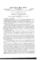
Be it known that I, DAVID H. LOWE, of Boston, in the county of Sufi'olk, and State of Massachusetts, have invented certain Improvements in Petroleum-Stoves, of which the following is a full, clear, and exact description, reference being had to the accompanying drawip-gs, making part of this specification, in which- Figure 1 is a perspective view of the interior of a petroleum-stove with my improvements applied thereto.
Figure 2 is a plan representing the interior of the stove, and a portion of the interior of the mechanism forming thesubject of my invention. I
Figure 3 is a vertical section through the stove, with my improvements in place thereon ready for use.
Figures 4 and Sam perspective views of the interior of a portion of my improved apparatus.
My invention relates to that class of stoves ordinarily denominated petroleum-stoves, in which naphtha, gasoline, &c., are employed as fuel, for heating and cooking; and my invention consists in combining with a petroleum-stove an apparatus for generating gas for illuminating purposes, the said apparatus being provided with a receptacle or meter for receiving the gas as it is produced from the naphtha or gasoline employed as fuel to heat the stove; and my invention also consists in attaching a lamp-burner to the reservoir containing the said material used as fuel.
To enable others skilled in the art to understand manner in which I have carried it out.
In the said drawings, A is the stove, of ciroular'form in the interior, near the bottom of which is placed a burner, B, secured to one endof a pipe, C, the other end of which enters the bottom of a receptacle, D, for containing the naphtha, gasoline, or other similar light grade of hydrocarbon-oil, to be used as fuel in heating the stove.
The pipe C is bent around, as shown in fig. 3, and extends over the flame of the burner 13, a fiat, circular dish, a, being interposed, in order to diffuse the rays of heat uniformly upon the lower surface ofthe kettle or other utensil placed in the hole 6 for its reception, in the top of the stove, by which means the utensil is not injured, as otherwise would be the case if the flame were allowed to concentrate atone point thereon. This pipe C is called the generating-pipe, and is provided with a wire-gauze packing, a, to regulate the How of the fluid down the pipe to the point where it is cgnvcrted by the heat into gas, a cock, (1, also'bcing provided for regulating the supply to the packing.
D is a. short nipple proceeding from one side of the burner 13. Over this nipple is screwed the lower end of a tube, E, the upper end of which is provided' with a cock, 0, which is connected with the lower or funnelshaped end of the reservoir or meter F, for holding the gas as it rises, when produced by the heat of the flame of and use my invention, I will proceed to describe the f is another tube, which forms a continuation ofthe tube E, being screwed into the top of the cook a, and passing up within the lower or funnel-shaped portion, 5, of the meter, and also up into the funnel-shaped bottom, of an inner receptacle, Gr, the oilice of the said tube being to convey the gases into the meter, the dry or pure the liquid or vapor contained in the gas is deposited and condensedon the under side of a circular plate, 2', placed directly over and at some distance from the said tube f. The condensed portion then runs down to the edge, 7, of the plate z, and falls into the funnel-shaped bottom, g, of the inner receptacle, and thence, through holes 7', down the insideof the bottom of the outer receptacle F. From this point it flows down a tube, H, one end of which is connected with the bottom of the receptacle F, and surrounds an inner tube, I, one end of which projects up from the bottom of the said receptacle F into the space between the funnel-shaped portions of the two receptacles, l and G.
The lower end of the outer tube II passes down inside the stove, above and near to the burner, and bends around, as shown in figs. 1 and 2, to the point k, where it is closed. The lowerportion of the inner tube passes through the outside tube H tea point, Z,wherc it terminates, this lower end of this inner tube being left open,
so as to allow the dry, pure gas, generated-from the heated. condensed vapors, to pass up therein, and into the circular chamber m, surrounding the inner receptacle, and thence, through holes n, into the space 0, below the perforated partition h. v i
The dry, pure gas thus produced in the pipes or tubes E and I, is then united, and passes through the perforated partition It to the pipe 1), to which is screwed the gas-cock 1' and burner s, by which construction I am enabled to obtain a constant supply of excellent gas for illuminating purposes.
The above-described apparatus can be compactly placed, and a flexible or rigid tube may be conducted to any point where light is desired.
Instead of a double tube, H I, a continuous single tube may be employed 'for collecting the condensed vapors, and generating therefrom a pure quality of gas, in which case, this tube would be provided with a wiregauze coil, to regulate the flow of the condensed vapors to the point where they become heated and are converted into dry gas, and when such tube is used, one of its ends must connect with the bottom of the inside of the meter, while the other end of the tube should extend up some distance above its bottom.
The interior of the reservoir containing the naphtha or gasoline is provided with a perforated funnel-shaped plate, t, to prevent explosion or accident, and, by making the said plate of the form shown in fig. s, so as to extend near the bottom of the reservoir, and providing the top of the reservoir with a cap, an ordinary lampburuer, K, may be secured thereto, and be usedto light the apartment in which, the stove is placed.
Claims.
What I claim as my invention, and desire to secure by Letters Patent, as ail-improvement in petroleumstoves, is-
The within-described apparatus, for producing gas for illuminating purposes, substantially as set forth. I also claim the combination of a lamp-burner with the reservoir 1), for containing the naphtha or gasoline,
substantially as described.
DAVID H. LOWE.
Witnesses N. W. S'rnAnNs, P. E. Tsseunmcunu.
Publications (1)
| Publication Number | Publication Date |
|---|---|
| US80980A true US80980A (en) | 1868-08-11 |
Family
ID=2150474
Family Applications (1)
| Application Number | Title | Priority Date | Filing Date |
|---|---|---|---|
| US80980D Expired - Lifetime US80980A (en) | Improvement in hydbooalffion-bdbnebs |
Country Status (1)
| Country | Link |
|---|---|
| US (1) | US80980A (en) |
-
0
- US US80980D patent/US80980A/en not_active Expired - Lifetime
Similar Documents
| Publication | Publication Date | Title |
|---|---|---|
| US80980A (en) | Improvement in hydbooalffion-bdbnebs | |
| US401096A (en) | altice | |
| US5210A (en) | coston | |
| US675919A (en) | Heating apparatus. | |
| US20567A (en) | Retort for generating gas | |
| US120302A (en) | Improvement in gas-machines | |
| US61454A (en) | Luke augustus plumb | |
| USRE1034E (en) | Improvement in vapor-lamps | |
| US51841A (en) | Improved apparatus for carbureting air | |
| US87886A (en) | Improvement in steam-heating- apparatus | |
| US84889A (en) | Improvement in gas-heaters | |
| US1105079A (en) | Hydrocarbon-burner. | |
| US397631A (en) | Vaporizer | |
| US42214A (en) | Improvement in vapor-stoves | |
| US306015A (en) | Hydrocarbon apparatus for heating and lighting | |
| US45568A (en) | Improved apparatus for vaporizing and aerating volatile hydrocarbon | |
| US1240389A (en) | Fluid-heater for lamps. | |
| US978901A (en) | Alcohol-lamp. | |
| US80918A (en) | Improved carburetor | |
| US55548A (en) | Improved apparatus for generating and washing gases for inhalation | |
| US52246A (en) | Hydrocarbon-stove | |
| US992404A (en) | Liquid-fuel burner. | |
| US123929A (en) | Improvement in carbureting-lamps | |
| US78465A (en) | Improved gas-machine | |
| US384873A (en) | Apparatus for burning crude petroleum-oil |