US809794A - Railroad system. - Google Patents
Railroad system. Download PDFInfo
- Publication number
- US809794A US809794A US27818405A US1905278184A US809794A US 809794 A US809794 A US 809794A US 27818405 A US27818405 A US 27818405A US 1905278184 A US1905278184 A US 1905278184A US 809794 A US809794 A US 809794A
- Authority
- US
- United States
- Prior art keywords
- train
- stop
- speed
- circuit
- section
- Prior art date
- Legal status (The legal status is an assumption and is not a legal conclusion. Google has not performed a legal analysis and makes no representation as to the accuracy of the status listed.)
- Expired - Lifetime
Links
- 238000009877 rendering Methods 0.000 description 3
- 230000000694 effects Effects 0.000 description 2
- 238000010276 construction Methods 0.000 description 1
- 230000000994 depressogenic effect Effects 0.000 description 1
- 239000012530 fluid Substances 0.000 description 1
- 238000009434 installation Methods 0.000 description 1
- 230000035515 penetration Effects 0.000 description 1
- 230000001105 regulatory effect Effects 0.000 description 1
Images

Classifications
-
- B—PERFORMING OPERATIONS; TRANSPORTING
- B61—RAILWAYS
- B61L—GUIDING RAILWAY TRAFFIC; ENSURING THE SAFETY OF RAILWAY TRAFFIC
- B61L23/00—Control, warning or like safety means along the route or between vehicles or trains
- B61L23/08—Control, warning or like safety means along the route or between vehicles or trains for controlling traffic in one direction only
- B61L23/14—Control, warning or like safety means along the route or between vehicles or trains for controlling traffic in one direction only automatically operated
- B61L23/16—Track circuits specially adapted for section blocking
- B61L23/166—Track circuits specially adapted for section blocking using alternating current
Definitions
- the present application relates to a special case of the above system in which the traveling zone of variable iniiuence created by the preceding train has only two grades or characters of influence which govern the following train to half-speed or full stop, respectively.
- the present case is, however, not limited to only two grades or characters in the Zone of influence, since three or four grades or characteristics could be used in practice.
- rI'he object of the present invention is to provide a system which shall be very simple and applicable to the railroad installations now in use, such as the interborough transit system of New York city.
- the invention further aims to secure a sufficiently perfect automatic control of trains for all practical purposes, securing a zone of inuence having two grades or characteristics, as above stated, and which shall employ only the usual train-stops and other devices commonly available.
- Figure 1 is a diagrammatic view showing a system embodying the principles of myinvention
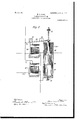
- Fig. 2 is a detail sectional view of a time-relay which may be used in connection with the above.
- the rules of the road provide that a following train may run by a caution-signal at reduced speed, but must come to 'a full stop whenever a home or danger signal is exhibited. This insures adequate protection if the rules of the road are always observed; but'an onerous duty is imposed upon the trainmen, who are liable to human negligence or error. In my present system the human element is eliminated.
- A denotes a portion of a railroad-track having rails A/ and A2.
- Rail A may be continuous and constitute a ground-return circuit.
- r[he rail A2 is divided into blocks BQ B2, and B2, 85e., which are insulated fromone another by insulatingjoints c. Between the different blocks are small insulated sections O, (J2, and C3 for purposes which will be later described.
- Each of the rail-sections B, B2, B2, Y, O2, O2, &c. is charged to a slight di'erence of potential over the continuous rail A by stepdown transformers E2 E, &c., supplied from the alternating-current mains Z' and Z2.
- stepdown transformers E2 E, &c. supplied from the alternating-current mains Z' and Z2.
- alternating-current magnets F, F2, and F3 Connected across each of such rail-sections are alternating-current magnets F, F2, and F3, which under normal conditions are energized to attract armatures 10, 102 ⁇ and 102 and 11', 112, and 112.
- an armature 142 is attracted, which completes a circuit as follows: Through IOS the wire m', armature 142, wire fm2, distant or caution signal L2, displaying clear therein, wire m2, magnet 152 to ground at m2.
- the magnet 132 has been energized, and in a similar way the magnets 13' and 132 are all continuously energized, which has the effect of displaying safety in each of the home or danger signals M', M2, and M2.
- the attraction of the armatures 14', 142, and 142 closes all of the circuits through all of the distant or caution signals L', L2, and L2, so that the latter are displayed to safety
- the magnet 152 was energized, and in like manner the magnets 15' and 152 are all energized to set the train-stops K', K2, and K2 to safety In other words, everything is in condition for the free passage of a train.
- I provide means for enforcing a reduction of speed when a caution-signal is passed, and for this purpose I have connected the trainstops K', K2, and K2 into circuit in a special way.
- the train-stop K2 is not thrown to stopthe train passing over it and does not become actuated until such train has entered section B' and released armature 11'. Trainstop K2 then becomes effective.
- the train-stop K2 is also effective to stop any train entering section B2; but when the train leaves section B2 circuit is again completed, and K2 returns to normal position unless its circuit is broken by certain other means.
- the train-stop K2 becomes ineffective or not to stop a following train according to the speed of the latter.
- the circuit through the train-stop K2 is completed through two separate branches 0' 02. If a caution-signal is displayed at L2, which occurs as long as a train is on section B2 by reason of the opening of the circuit of magnet 132 at 102 and also as long as the train is on section B' by reason of the opening of the circuit at 11', the connection at 02 will be broken.
- the only way the train-stop K2 can be set to allow a train to pass while the caution-signal L3 is displayed is through the branch o'.
- the train-stop cannot be set to let a following train pass, since its circuit is broken at 112; but when the train has left section ⁇ B2 armature 112 rises, and the train-stop K2 can receive current provided the circuit is completed through branch o'.
- the circuit is or is not completed in this branch 0', according to the speed of the following train.
- an alternating-current magnet D2 is denergized and an armature 162 released, which opens a circuit through a solenoid-magnet 17 2, which is particularly illustrated in Fig. 2.
- the armature 18 of the solenoid-magnet 17 is permitted to drop with a slow movement of a predetermined speed, and for this purpose I have arranged a fluid-cylinder 19, containing a weighted piston 20, attached to the armature 18.
- 21 indicates an adjustable valve by which the fluid is permitted to escape from the cylinder 19, so that the weighted piston 20 drops with a graduated speed in accordance with the adjustment of the valve 21.
- the circuit of the magnet 272 is completed as follows: Immediately when the train has passed over the small section C2, so as to enter the section B2, the armature 112 is released and the circuit of the magnet 272, which receives its current from the wires m2 and m2, is broken.
- the system is effective to absolutely preclude the possibility of collisions, since it is wholly automatic, and it further has the effect of discouraging an attempt to pass a cautionsignal at too high speed, since the penalty of total stoppage is automatically and certainly infiicted if the speed in passing the cautionsignal is the least bit too high.
- my invention is not limited to the use of' speed-controlling devices along the track subdivisions or units.
- the invention is equally applicable to use with any form of governor-controlled tappet upon the train which serves to mechanically open the switches 26', 262, and 263 as the train passes the successive sections in case its speed is too high.
- any form of governor-controlled tappet upon the train which serves to mechanically open the switches 26', 262, and 263 as the train passes the successive sections in case its speed is too high.
- means by which the train is made effective to open the switches 26', 262, and 263 in case its speed is too high is not important, it being merely essential to deeise some means by which this is accomplished in connection with an electrical system for rendering the train-stop ef'- fective in case the caution-signal is simultaneously displayed.
- a track divided into sections means whereby caution-signal circuits are successively opened by the passage ofl a train, each caution-signal circuit constituting a branch of a circuit operatinga trainstop.
- a track divided into sections means whereby a train absolutely stops a following train a certain distance behind, and stops the following train an increased distance behind in case its speed exceeds a certain amount.
- a track divided into sections, and means operated from a passing ⁇ train for setting a train-stop in the rear thereof', and means for rendering said train-stop ineffective in case the speed of' the following train is below a certain value.
- a track divided into sections, and means operated from a passing train for settingI a train-stop in the rear thereof, and means for rendering said train-stop operable only in case the speed of the following train exceeds a certain value.
- a track divided into sections means whereby said sections are short-circuited by the passage of a train, a magnet which releases a slowly-movable part actutated by the short-circuiting of one section, and a second magnet actuated by the following section for releasing its armature unless held up by said part.
- a track divided into sections means whereby a train-stop is made effective at the entrance to a section, after, but not while, a train is located thereon, and means whereby said train-stop can be rendered ineffective by trains below a certain speed after the preceding train has traversed a certain distance.
- Inarailroad system atrack divided into sections, and means whereby a preceding train causes behind it a traveling Zone of variable ⁇ influence, and means whereby a following train is absolutely stopped or stopped in case its speed is too great, accordingI to its penetration into such Zone.
Landscapes
- Engineering & Computer Science (AREA)
- Mechanical Engineering (AREA)
- Train Traffic Observation, Control, And Security (AREA)
Description
No. 809,794. PATENTED JAN. 9,1906. H. C. FORD.
RAILROAD SYSTEM.
APPLICATION FILED SBPTJZ, 1905.
2 SHEETS-SHEET 2.
' @agg/Lito@ J c w HANNIBAL O. FORD, OF JAMAICA, NEIV YORK.
RAILROAD SYSTEM.
Specification of Letters Patent.
Patented Jan. 9,1906.
Application filed September 12l 1905. Serial No. 278.184.
To all whom, it may concern.-
Be it known that I, HANNIBAL C. FORD, a citizen of the United States, residing at Jamaica, in the county of Queens and State of New York, have invented certain new and useful Improvements in Railroad Systems, of which the following is a full, clear, and exact description.
In my companion application, Serial No. 278,183, led herewith, I have set forth in its broad aspects a railroad system in which each train produces in its rear a traveling Zone of variable influence which serves to automatically g'overn the speed of the following train entering said zone.
The present application relates to a special case of the above system in which the traveling zone of variable iniiuence created by the preceding train has only two grades or characters of influence which govern the following train to half-speed or full stop, respectively. The present case is, however, not limited to only two grades or characters in the Zone of influence, since three or four grades or characteristics could be used in practice.
rI'he object of the present invention is to provide a system which shall be very simple and applicable to the railroad installations now in use, such as the interborough transit system of New York city.
The invention further aims to secure a sufficiently perfect automatic control of trains for all practical purposes, securing a zone of inuence having two grades or characteristics, as above stated, and which shall employ only the usual train-stops and other devices commonly available.
Vith these and other objects in view my invention consists in the construction, conibination, location, and arrangement of parts, all as will be more fully hereinafter set forth, as shown in the accompanying drawings, and finally particularly pointed out in the appended claims.
Referring to the drawings, Figure 1 is a diagrammatic view showing a system embodying the principles of myinvention; and Fig. 2 is a detail sectional view of a time-relay which may be used in connection with the above.
A form of block system which is nowextensively used, and particularly in the subway system of New York city, involves the subdivision of the track into sections or blocks the rails of which are separately charged by transformers. As the trains progress along this track the sections are successively shortcircuited and relay-magnets denergized to display home or danger77 and distant or caution signals behind the train. The rules of the road provide that a following train may run by a caution-signal at reduced speed, but must come to 'a full stop whenever a home or danger signal is exhibited. This insures adequate protection if the rules of the road are always observed; but'an onerous duty is imposed upon the trainmen, who are liable to human negligence or error. In my present system the human element is eliminated.
Referring to the drawings, A denotes a portion of a railroad-track having rails A/ and A2. Rail A may be continuous and constitute a ground-return circuit. r[he rail A2 is divided into blocks BQ B2, and B2, 85e., which are insulated fromone another by insulatingjoints c. Between the different blocks are small insulated sections O, (J2, and C3 for purposes which will be later described.
Each of the rail-sections B, B2, B2, Y, O2, O2, &c., is charged to a slight di'erence of potential over the continuous rail A by stepdown transformers E2 E, &c., supplied from the alternating-current mains Z' and Z2. Connected across each of such rail-sections are alternating-current magnets F, F2, and F3, which under normal conditions are energized to attract armatures 10, 102` and 102 and 11', 112, and 112. In Fig. 1 all of the above-named armatures are shown attracted, which constitutes the normal safety condition of the road when no trains are passing.
By means of the above armatures certain electrical circuits are normally completed, as follows: Starting from a source of electric potential represented by the line-wire fn/ circuit is made, through wire 112, armature 11', wire v2.2, into armature 10, where it divides, part going through a train-stop K2, (the mechanical features of which are diagrammatically indicated adjacent the rails at the entrance to the section,) wire af, armatures 122 and 262, back to the negative main a5. In this way the train-stop K2 is depressed into its nonoperative relation. The other branch of the circuit of wire a traverses the armature 102, wire a, home signal M2, magnet 132 to ground. By this means an armature 142 is attracted, which completes a circuit as follows: Through IOS the wire m', armature 142, wire fm2, distant or caution signal L2, displaying clear therein, wire m2, magnet 152 to ground at m2.
By the completion of the above circuits it will be observed that the magnet 132 has been energized, and in a similar way the magnets 13' and 132 are all continuously energized, which has the effect of displaying safety in each of the home or danger signals M', M2, and M2. At the same time the attraction of the armatures 14', 142, and 142 closes all of the circuits through all of the distant or caution signals L', L2, and L2, so that the latter are displayed to safety It will also be noted that the magnet 152 was energized, and in like manner the magnets 15' and 152 are all energized to set the train-stops K', K2, and K2 to safety In other words, everything is in condition for the free passage of a train.
I will now imagine a train to 'pass onto the track from right to left, successively traversing blocks B2 B2 and occupying B'. Vhen the train is in this position, magnet F' will be denergized; but the magnets F2 and F2 will have again attracted their armatures. The result is to denergize magnets 13' and 132, displaying a danger-signal at M' and M2, and by the release of armatures 14 and 142 to display caution or distant signals L2 L2. In other words, danger-signals are exhibited in the blocks occupied by and next to the rear of the train and a caution-signal at the entrance to the next block still farther in the rear thereof. These features constitute, generally, the block-signal system now in use, and up to this point I have not particularly referred to the special features of my invention.
I provide means for enforcing a reduction of speed when a caution-signal is passed, and for this purpose I have connected the trainstops K', K2, and K2 into circuit in a special way. The presence of a train on section B2, but which has not yet arrived on section B', releases the armatures 102 and 112; but the circuit through the train-stop K2 is still completed by the armature 11', which is still attracted. Thus the train-stop K2 is not thrown to stopthe train passing over it and does not become actuated until such train has entered section B' and released armature 11'. Trainstop K2 then becomes effective. So long as the train is on section B2 the train-stop K2 is also effective to stop any train entering section B2; but when the train leaves section B2 circuit is again completed, and K2 returns to normal position unless its circuit is broken by certain other means. In accordance with my invention the train-stop K2 becomes ineffective or not to stop a following train according to the speed of the latter. The circuit through the train-stop K2 is completed through two separate branches 0' 02. If a caution-signal is displayed at L2, which occurs as long as a train is on section B2 by reason of the opening of the circuit of magnet 132 at 102 and also as long as the train is on section B' by reason of the opening of the circuit at 11', the connection at 02 will be broken. Accordingly the only way the train-stop K2 can be set to allow a train to pass while the caution-signal L3 is displayed is through the branch o'. As long as a train is on section B2the train-stop cannot be set to let a following train pass, since its circuit is broken at 112; but when the train has left section`B2 armature 112 rises, and the train-stop K2 can receive current provided the circuit is completed through branch o'. The circuit is or is not completed in this branch 0', according to the speed of the following train. As the following train passes onto the subsection ()2 (it being understood that the preceding train has wholly entered block B') an alternating-current magnet D2 is denergized and an armature 162 released, which opens a circuit through a solenoid-magnet 17 2, which is particularly illustrated in Fig. 2. The armature 18 of the solenoid-magnet 17 is permitted to drop with a slow movement of a predetermined speed, and for this purpose I have arranged a fluid-cylinder 19, containing a weighted piston 20, attached to the armature 18. 21 indicates an adjustable valve by which the fluid is permitted to escape from the cylinder 19, so that the weighted piston 20 drops with a graduated speed in accordance with the adjustment of the valve 21. Under these circumstances the armature 18 falls slowly, and after a certain predetermined time, which can be regulated by the adjustment of the nuts 22, the latter strikes a tilting lever 23, pivoted at 24 upon the frame of the device, causing such lever to pass beneath a hook 25 on a pivoted armature 26 of a magnet 272. Referring again to Fig. 1, the circuit of the magnet 272 is completed as follows: Immediately when the train has passed over the small section C2, so as to enter the section B2, the armature 112 is released and the circuit of the magnet 272, which receives its current from the wires m2 and m2, is broken. Accordingly the armature 26 will be released, and branch circuit 0', above referred to, will be broken, provided the train has been moving so rapidly as to arrive at section B2 before the nuts 22 have tilted the lever 23. Should thelatter occur, the hook 25 will be engaged and mechanically prevent the branch circuit 0' from being broken. The result has been that as long as a train is on section B2 train-stop K2 would be eiective under any circumstances and stop the train from entering section B2. Then the preceding train has left section B2, the cautionsignal L2is still displayed; but train-stop K2 is ineffective to stop ensuing trains, unless the branch circuit 0' is broken. The following If the preceding IOO IIO
train has left section B', the branch 02. above referred to, is completed, so that `the trainstop is released, whether or not the following train traverses at such high speed as to open the branch circuit 0'. As soon as the following train has left the short section C3 the magnet 173 is energized to raise its armature 2O and restore all the apparatus to normal relation. Thus it will be seen that behind each train I leave a traveling zone of variable influence, causing the absolute stoppage of a following train in case it is within a certain distance, but the qualified stoppage of a following train, if it is a one block greater distance, depending on whetheror not the engineer has sufliciently reduced his speed. In practice the aparatus would ,be so adjusted that the following train would be obliged to run at half-speed in order to pass a cautionsignal.
The system is effective to absolutely preclude the possibility of collisions, since it is wholly automatic, and it further has the effect of discouraging an attempt to pass a cautionsignal at too high speed, since the penalty of total stoppage is automatically and certainly infiicted if the speed in passing the cautionsignal is the least bit too high.
It is to be understood that my invention is not limited to the use of' speed-controlling devices along the track subdivisions or units. The invention is equally applicable to use with any form of governor-controlled tappet upon the train which serves to mechanically open the switches 26', 262, and 263 as the train passes the successive sections in case its speed is too high. rIhe particular form of means by which the train is made effective to open the switches 26', 262, and 263 in case its speed is too high is not important, it being merely essential to deeise some means by which this is accomplished in connection with an electrical system for rendering the train-stop ef'- fective in case the caution-signal is simultaneously displayed.
That I claim isl. In a railroad system, a track divided into sections, and electrical connections for setting a train-stop absolutely to enforce a home or danger signal, but releasably to enforce a caution-signal depending on the speed of a following train.
2. In a railroad system, a track divided into sections, a train-stop corresponding to each caution-signal, and means whereby said trainstop is rendered ineffective when the speed of a following train falls below a certain amount.
In a railroad system, a track divided into sections, means whereby caution-signal circuits are successively opened by the passage ofl a train, each caution-signal circuit constituting a branch of a circuit operatinga trainstop.
4. In a railroad system, a track divided into sections, means whereby a train absolutely stops a following train a certain distance behind, and stops the following train an increased distance behind in case its speed exceeds a certain amount.
In a railroad system, a track divided into sections, andv connections for stopping' a following train in case its speed exceeds a certain amount.
. In a railroad system, a track divided into sections, and means operated from a passing` train for setting a train-stop in the rear thereof', and means for rendering said train-stop ineffective in case the speed of' the following train is below a certain value.
7. In arailroad system, a track divided into sections, and means operated from a passing train for settingI a train-stop in the rear thereof, and means for rendering said train-stop operable only in case the speed of the following train exceeds a certain value.
8. In a railroad system, electrical connections f`or displaying a home signal in the rear of a train, means whereby such home signal displays a distant signal farther in the rear, a train-stop, and means whereby said trainstop is absolutely effective as long as the home signal is displayed and is effective for high-speed trains only as long as the distant signal is displayed.
9. In a railroad system, a track divided into sections, means whereby said sections are short-circuited by the passage of a train, a magnet which releases a slowly-movable part actutated by the short-circuiting of one section, and a second magnet actuated by the following section for releasing its armature unless held up by said part.
l0. In a railroad system, a track divided into sections, means whereby a train-stop is made effective at the entrance to a section, after, but not while, a train is located thereon, and means whereby said train-stop can be rendered ineffective by trains below a certain speed after the preceding train has traversed a certain distance.
l1. Inarailroad system, atrack divided into sections, and means whereby a preceding train causes behind it a traveling Zone of variable `influence, and means whereby a following train is absolutely stopped or stopped in case its speed is too great, accordingI to its penetration into such Zone.
In witness whereof' I subscribe my signature in the presence of two witnesses.
' HANNIBAL C. FORD.
Titnessesz ALFRED W. Pnocron, IVALDO M. CHAPIN.
Priority Applications (1)
| Application Number | Priority Date | Filing Date | Title |
|---|---|---|---|
| US27818405A US809794A (en) | 1905-09-12 | 1905-09-12 | Railroad system. |
Applications Claiming Priority (1)
| Application Number | Priority Date | Filing Date | Title |
|---|---|---|---|
| US27818405A US809794A (en) | 1905-09-12 | 1905-09-12 | Railroad system. |
Publications (1)
| Publication Number | Publication Date |
|---|---|
| US809794A true US809794A (en) | 1906-01-09 |
Family
ID=2878275
Family Applications (1)
| Application Number | Title | Priority Date | Filing Date |
|---|---|---|---|
| US27818405A Expired - Lifetime US809794A (en) | 1905-09-12 | 1905-09-12 | Railroad system. |
Country Status (1)
| Country | Link |
|---|---|
| US (1) | US809794A (en) |
-
1905
- 1905-09-12 US US27818405A patent/US809794A/en not_active Expired - Lifetime
Similar Documents
| Publication | Publication Date | Title |
|---|---|---|
| US2293926A (en) | Wallace | |
| US809794A (en) | Railroad system. | |
| US233746A (en) | Electric railway-signaling apparatus | |
| US898221A (en) | Railway electric signaling system. | |
| US292744A (en) | g-assett | |
| US842285A (en) | Block-signaling system for railways. | |
| US1002087A (en) | Railway-signal. | |
| US1223685A (en) | Permissive automatic train-stop. | |
| US1163720A (en) | Railway signaling. | |
| US515648A (en) | Automatic -electric railway signal system | |
| US852628A (en) | Automatic electrical train-stop. | |
| US2000871A (en) | Railway traffic controlling apparatus | |
| US1864481A (en) | Railway traffic controlling apparatus | |
| US1111394A (en) | Electric train-control system. | |
| US1797560A (en) | Railway-traffic-controlling apparatus | |
| US788513A (en) | Railway signal system. | |
| US1510496A (en) | Winthrop k | |
| US2098719A (en) | Railway signaling system and apparatus | |
| US427387A (en) | Railway signaling apparatus | |
| US482423A (en) | Railway-crossing protector | |
| US908979A (en) | Automatic switch-lock. | |
| US1224111A (en) | Switch-indicator. | |
| US799807A (en) | Block-signal system. | |
| US482422A (en) | Railway-crossing protector | |
| US396748A (en) | kookoaey |