US809776A - Shuttle-motion for looms. - Google Patents
Shuttle-motion for looms. Download PDFInfo
- Publication number
- US809776A US809776A US26078705A US1905260787A US809776A US 809776 A US809776 A US 809776A US 26078705 A US26078705 A US 26078705A US 1905260787 A US1905260787 A US 1905260787A US 809776 A US809776 A US 809776A
- Authority
- US
- United States
- Prior art keywords
- wheels
- chains
- sheaves
- motion
- shuttle
- Prior art date
- Legal status (The legal status is an assumption and is not a legal conclusion. Google has not performed a legal analysis and makes no representation as to the accuracy of the status listed.)
- Expired - Lifetime
Links
Images

Classifications
-
- D—TEXTILES; PAPER
- D03—WEAVING
- D03D—WOVEN FABRICS; METHODS OF WEAVING; LOOMS
- D03D49/00—Details or constructional features not specially adapted for looms of a particular type
- D03D49/24—Mechanisms for inserting shuttle in shed
- D03D49/46—Mechanisms for inserting shuttle in shed wherein the shuttle is pushed or pulled positively
Definitions
- This invention relates to shuttle-motions for looms; and the primary object of the invention is the provision of sim le and effective means for avoiding the slac in the chains employed to cooperate with other devices in reciprocating the shuttle-bars.
- the invention is capable of advantageous incorporation in'various kinds of looms, but more especially in those adapted for weaving wire fabric.
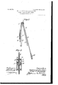
- Figure 1 is a front elevation, and Fig. 2 an end or side elevation, of a portion of the said loom with our shuttle-motion therein.
- Fig. 3 is a vertical central section of a plate or board hereinafter described and the eccentrically mounted wheels thereon and upon an enlarged scale.
- the numeral 2 denotes the frame of the loom, from the upper part of which is swung the lathe-frame or, as it is sometimes known, beater 3.
- a plate or board 4 Connecting the upper and lower cross-bars of the latheframe or beater 3 and naturally forming part of the said lathe-frame is a plate or board 4, which supports upon opposite sides the chainwheels, each designated by 5.
- chains, as 6, fastened in some convenient way in peripheral grooves in the chain-wheels. It will be understood that we use the term chains in a generic sense to include other than link constructions, the term in question being adopted simply, as it is afamiliar one in this art.
- the chains diverge upwardly from the chain- Wheels and pass in contact with guides, as 7, in horizontal alinement with each other, said guides being shown as sheaves or pulleys rotatively supported upon the loom-frame 2.
- the chains are then continued outward and are passed over other guides, as 8, and depend therefrom.
- the last-lnentioned guides 8 may, like the others, consist of pulleys or sheaves, also connected with the framework2. hile the guides 7 and S are in horizontal line, they are laterally separated, although this is not essential.
- Each chain-wheel is of circular form; but they are both eccentrically mounted, they being fixedly secured in some suitable manner upon a ournal or pivot 11.
- the plate or upright 4 is provided upon its opposite faces with coinciding outwardly-extended bosses presenting a hub 12, in which the journal or pivot 11 rotates.
- the opposite ends of the journal or pivot are contiguous to the inner faces of the wheels, the three parts being shown as fixedly united by pins, as 13, pass ing entirely through them and which may conveniently consist of rivets headed at their opposite ends in order to hold the two wheels and supporting-journal in rigid relation.
- the chains 6 are set in annular grooves or channels in the rims 14, applying their stress directly over the axle or journal 11.
Landscapes
- Engineering & Computer Science (AREA)
- Textile Engineering (AREA)
- Looms (AREA)
Description
No. 809,776. PATENTED JAN. 9, 1906. M. L. CHRISTIAN & E. E. REYNOLDS.
SHUTTLE MOTION FOR LOOMS.
APPLICATION FILED MAYI'Y. 1905.
2 SHEETSSHBET 1.
No. 809,776. PATENTED JAN. 9, 1906. M. L. CHRISTIAN & E. E. REYNOLDS. SHUTTLE MOTION FOR LOOMS.
APPLICATION FILED MAY17. 1905.
2 SHEETS-SHEET 2.
man
5' rTED 'sTATEs- PATENT oEEroE.
MADISON L. CHRISTIAN AND EL'MER E. REYNOLDS, OF CLINTON, IOWA, ASSIGNORS TO AMERICAN IRE CLOTH COMPANY, OF, CLINTON, IOWA,
A CORPORATION OF IOWA.
SHUTTLE-MOTION FOR LOOIVIS.
Specification of Letters Patent.
Patented Jan. 9, 1906.
To aZZ 1072,0111, it may concern.-
Be it known that we, MADIsoN L. CHRIS- TIAN and EIMER E. REYNOLDS, citizens of the United States, residing at Clinton, in the county of Clinton and State of Iowa, have invented new and useful Improvements in Shuttle-Motions for Looms, of which the following is a specification.
This invention relates to shuttle-motions for looms; and the primary object of the invention is the provision of sim le and effective means for avoiding the slac in the chains employed to cooperate with other devices in reciprocating the shuttle-bars.
The invention is capable of advantageous incorporation in'various kinds of looms, but more especially in those adapted for weaving wire fabric.
The invention includes other objects and advantages which, with the foregoing, will be set forth at length in the following description, while the novelty of the invention will be involved in the claims succeeding said description.
In the drawings accompanying and forming a part of this specification we illustrate in part a loom for weaving wire fabric in which is re resented as embodied a shuttlemotion inc uding our invention, and we will in order to enable those skilled in the art to practice the invention describe briefly the loom construction and in detail the shuttlemotion thus represented; but of course the invention is not limited to the exact disclosure thus made, for certain variations may be adopted within the scope of our claims.
Referring to the drawings, Figure 1 is a front elevation, and Fig. 2 an end or side elevation, of a portion of the said loom with our shuttle-motion therein. Fig. 3 is a vertical central section of a plate or board hereinafter described and the eccentrically mounted wheels thereon and upon an enlarged scale.
Like characters refer to like parts throughout the views.
In the drawings the numeral 2 denotes the frame of the loom, from the upper part of which is swung the lathe-frame or, as it is sometimes known, beater 3. Connecting the upper and lower cross-bars of the latheframe or beater 3 and naturally forming part of the said lathe-frame is a plate or board 4, which supports upon opposite sides the chainwheels, each designated by 5. To the chainwheels 5 are attached chains, as 6, fastened in some convenient way in peripheral grooves in the chain-wheels. It will be understood that we use the term chains in a generic sense to include other than link constructions, the term in question being adopted simply, as it is afamiliar one in this art. The chains diverge upwardly from the chain- Wheels and pass in contact with guides, as 7, in horizontal alinement with each other, said guides being shown as sheaves or pulleys rotatively supported upon the loom-frame 2. The chains are then continued outward and are passed over other guides, as 8, and depend therefrom. The last-lnentioned guides 8 may, like the others, consist of pulleys or sheaves, also connected with the framework2. hile the guides 7 and S are in horizontal line, they are laterally separated, although this is not essential. T o the pendent outer ends of the chains rods 9 are shown as connected, said rods being jointed at their lower ends to oppositely-disposed cranks upon the crank-shaft 10, which may be operated in the customary manner in order, through its intermediate described connections with the two chain-wheels 5, to turn the same. wheel when operated from the operating crank makes one full turn, and as the cranks operate there will be a slight slack in each chain as it is wound onto or unwound from its appropriate wheel, and we avoid'this slack by the peculiar construction of wheels herelnafter more particularly described.
To the chainwheels are connected the usual rods for throwing the shuttle and which need not be described in detail. Those points upon the pulleys or sheaves 7 which are engaged by the chains 6 are in horizontal alinement in the present case with the axis of mo tion of the lathe-frame or beater 3, so that as said heater swings or oscillates there will be no pull upon either chain, the conse uence being that side pull or drag upon the atheframe or beater is wholly avoided, whereby rapidity and ease of operation will be assured, which are important considerations. It naturally follows that by reason of the described construction we eliminate wholly the slack in the chain due to the vibration of the lathe frame or beater. As previously indicated,
there will be slack in the chains due to the Each action of the two cranks upon the opposite ends of the shaft 10; but we provide for taking this slack up by a peculiar construction of chain-wheel, as willnow appear.
Each chain-wheel is of circular form; but they are both eccentrically mounted, they being fixedly secured in some suitable manner upon a ournal or pivot 11. The plate or upright 4 is provided upon its opposite faces with coinciding outwardly-extended bosses presenting a hub 12, in which the journal or pivot 11 rotates. The opposite ends of the journal or pivot are contiguous to the inner faces of the wheels, the three parts being shown as fixedly united by pins, as 13, pass ing entirely through them and which may conveniently consist of rivets headed at their opposite ends in order to hold the two wheels and supporting-journal in rigid relation.
By the construction just described we provide a long wide bearing for the wheels, insuring stability of bearing and a smooth and true motion of the wheels, and consequently of the parts receiving their motion therefrom. Upon the wheels are inwardly-extending'rims 14, which are the only parts of said wheels which are contiguous, or substantially so, with the upright 4, so that we reduce to the least possible extent the friction between the wheels and the said upright, and thereby can operate the wheels with a minimum of power.
The chains 6 are set in annular grooves or channels in the rims 14, applying their stress directly over the axle or journal 11. By reason of the eccentric mounting of the two circular wheels it will be apparentthat as they rotate they take up by their eccentricity all slack in the chains caused by the opera tion of the cranks at the ends of the shaft 10,
while all side drag upon the frame 3 as it 3. The combination of a lathe-frame hav-v ing circular chain-wheels eccentrically mounted, sheaves on the loomframework, and
chains connected with the said chain-wheelsand passing over the sheaves, the points on the sheaves which are engaged by the chain wheels being in line with each other and with the axis of motion of the latheframe.
4. The combination of a lathe-frame having chain-wheels, sheaves on the loom-framework, chains connected with said chainwheels and passing over the sheaves, the points of contact of the sheaves engaged by the chains being in line with each other and with the axis of motion of the lathe-frame, and sheaves mounted on said loom-framework in horizontal alinement with said firstmentioned sheaves and over which the chains pass.
5. The combination of a lathe-frame having circular chain-wheels eccentrically mounted, sheaves on the loom-framework, chains connected with the chain-wheels and passing over the sheaves, the points on the sheaves which are engaged bythe chains being inline with each other and with axis of motion of the lathe-frame, and sheaves on the loomframework over which the chains pass and in horizontal alinement with the first-mentioned sheaves.
In testimony whereof we have hereunto set our hands in presence of two subscribing witnesses.
MADISON L. CHRISTIAN. ELMER E. REYNOLDS.
Witnesses:
A. H. I'IAMMARSTROM, G. A. HAMiL'roN.
Priority Applications (1)
| Application Number | Priority Date | Filing Date | Title |
|---|---|---|---|
| US26078705A US809776A (en) | 1905-05-17 | 1905-05-17 | Shuttle-motion for looms. |
Applications Claiming Priority (1)
| Application Number | Priority Date | Filing Date | Title |
|---|---|---|---|
| US26078705A US809776A (en) | 1905-05-17 | 1905-05-17 | Shuttle-motion for looms. |
Publications (1)
| Publication Number | Publication Date |
|---|---|
| US809776A true US809776A (en) | 1906-01-09 |
Family
ID=2878257
Family Applications (1)
| Application Number | Title | Priority Date | Filing Date |
|---|---|---|---|
| US26078705A Expired - Lifetime US809776A (en) | 1905-05-17 | 1905-05-17 | Shuttle-motion for looms. |
Country Status (1)
| Country | Link |
|---|---|
| US (1) | US809776A (en) |
-
1905
- 1905-05-17 US US26078705A patent/US809776A/en not_active Expired - Lifetime
Similar Documents
| Publication | Publication Date | Title |
|---|---|---|
| US1369356A (en) | Motorcycle | |
| US809776A (en) | Shuttle-motion for looms. | |
| US492144A (en) | The nohris peters co | |
| US204466A (en) | Improvement in shedding mechanisms for fancy-looms | |
| US400742A (en) | Shuttle motion foe looms | |
| US673839A (en) | Shuttle-motion for looms. | |
| US1214525A (en) | Embroidering-machine. | |
| US499170A (en) | Emanuel keuser | |
| US569980A (en) | Wool-washing machine | |
| US776584A (en) | Picker-stick motion for looms. | |
| US503956A (en) | Positive shuttle motion fob looms | |
| US495766A (en) | Itnesses | |
| US468133A (en) | Francis j | |
| US865234A (en) | Thread take-up for sewing-machines. | |
| US1001804A (en) | Let-off mechanism for narrow-ware looms. | |
| US944656A (en) | Driving mechanism for washing-machines. | |
| US1326309A (en) | Island | |
| US1236605A (en) | Actuating means for operating washing-machines. | |
| US774696A (en) | Traverse mechanism for warper-combs. | |
| US986805A (en) | Operating means for washing-machines. | |
| US565904A (en) | Thomas kerker | |
| US125554A (en) | Improvement in washing-machines | |
| US977702A (en) | Automatic centering device for endless aprons. | |
| US1539043A (en) | Tension mechanism for looms | |
| US87528A (en) | Improvement in stop-motion mechanism for warping-machine |