US80976A - Improved brick-machine - Google Patents
Improved brick-machine Download PDFInfo
- Publication number
- US80976A US80976A US80976DA US80976A US 80976 A US80976 A US 80976A US 80976D A US80976D A US 80976DA US 80976 A US80976 A US 80976A
- Authority
- US
- United States
- Prior art keywords
- crank
- machine
- press
- shaft
- brick
- Prior art date
- Legal status (The legal status is an assumption and is not a legal conclusion. Google has not performed a legal analysis and makes no representation as to the accuracy of the status listed.)
- Expired - Lifetime
Links
- 239000011449 brick Substances 0.000 description 14
- 238000010168 coupling process Methods 0.000 description 6
- 238000005859 coupling reaction Methods 0.000 description 6
- 229910001018 Cast iron Inorganic materials 0.000 description 4
- 230000001808 coupling Effects 0.000 description 4
- 241000726123 Acanthurus Species 0.000 description 2
- 241000375392 Tana Species 0.000 description 2
- 239000004927 clay Substances 0.000 description 2
- 229910052570 clay Inorganic materials 0.000 description 2
- 230000023298 conjugation with cellular fusion Effects 0.000 description 2
- 230000000875 corresponding Effects 0.000 description 2
- 230000003203 everyday Effects 0.000 description 2
- 230000013011 mating Effects 0.000 description 2
- 239000004570 mortar (masonry) Substances 0.000 description 2
- 230000000414 obstructive Effects 0.000 description 2
- 239000004575 stone Substances 0.000 description 2
- 230000021037 unidirectional conjugation Effects 0.000 description 2
Images

Classifications
-
- B—PERFORMING OPERATIONS; TRANSPORTING
- B29—WORKING OF PLASTICS; WORKING OF SUBSTANCES IN A PLASTIC STATE IN GENERAL
- B29C—SHAPING OR JOINING OF PLASTICS; SHAPING OF MATERIAL IN A PLASTIC STATE, NOT OTHERWISE PROVIDED FOR; AFTER-TREATMENT OF THE SHAPED PRODUCTS, e.g. REPAIRING
- B29C49/00—Blow-moulding, i.e. blowing a preform or parison to a desired shape within a mould; Apparatus therefor
- B29C49/02—Combined blow-moulding and manufacture of the preform or the parison
- B29C49/06—Injection blow-moulding
-
- B—PERFORMING OPERATIONS; TRANSPORTING
- B29—WORKING OF PLASTICS; WORKING OF SUBSTANCES IN A PLASTIC STATE IN GENERAL
- B29C—SHAPING OR JOINING OF PLASTICS; SHAPING OF MATERIAL IN A PLASTIC STATE, NOT OTHERWISE PROVIDED FOR; AFTER-TREATMENT OF THE SHAPED PRODUCTS, e.g. REPAIRING
- B29C49/00—Blow-moulding, i.e. blowing a preform or parison to a desired shape within a mould; Apparatus therefor
- B29C49/02—Combined blow-moulding and manufacture of the preform or the parison
- B29C2049/023—Combined blow-moulding and manufacture of the preform or the parison using inherent heat of the preform, i.e. 1 step blow moulding
Definitions
- alla dnmle referat it infilare etters rtmt mit mating part nf tip tana.
- Figure 2 is a front view of the same.
- Figure 3 is a detail view, showingmy improved method of securing the Scrapers and knives tol the hollow cast-iron shaft.
- This invention relatesto certain new and useful improvements on J. A. Laflers patent brick-machine, No. 37,3448, whereby it is made adaptable for making either common or pressed brick, at will, and whereby its general eii'iciency and usefulness are much increased, as hereinafter set forth.
- this slide B is to close the upper side of the press-box A when the mould and clod-crusher F are forced up, so that the clay or mortar cannot return from the press-box to the grind-mill Gr, when pressure is applied to the said mould and clod-crusher for making pressed bricks.
- the slide B When making common bricks, the slide B is not necessary, and can be thrown out of action by disengaging the connecting-rod el from the crank D.
- the working of :the machine can be changed from common to pressed brick, or vice versa, at any time within fifteen minutes.
- crank-shaft,- z' I For operating the swinging frame H by the grinding-power, a short crank-shaft,- z' I, g. 2, is placed over the grind-mill, and geared to'the main shaft E by gears J.
- the crank z' is loose on its shaft I, but i's made to engage with the shaft by means of a clutch-coupling, k,land connection.is made between the crank z and the swinging frame H through a, connecting-rod and chain, L Z, pulley M windlass-shaft m', and chains n n.
- clutch k is 'so constructed that it willjremain engaged onlyr when the crank z' is overcoming resistanee,.and when the crank is lifting Athe press-frame H the forward motion of the crank is resisted by the weight of said press'- frame, but as soon as the crank has passed its upper dead-point, the connection L Z passes to the front of the crank, so that the weight of the-press is thrown on the forward side of the crank, and as the weight of the press then pulls forward on the crank, instead of resisting its motion, the coupling k disengages, and the crank falls forward through half a revolution, letting the press-frame drop so that the press is opened immediately, and by this means time is saved in opening thc press.
- the bed h, of the swinging frame H is supported by cams r r, iig. 2, on the shaftltig. 1, and these shafts E R are supported by elastic cushions, P P, of rubber.
- These elastic supports allow a slight yielding of the bed L, when small-stone or' other obstructions protrude from the mould as it is being drawn but; and the cushions also keep thc'mould snug up tothe clod-crusher, so-'that they are struck off closely when'withdraw from under the clod-crusher.
- I secure the scrapersS and knives s in the hollow cast-iron main shaft E, ⁇ iig. l, as follows: A hole or mortise is cast in the shaft for each knife or scraper, and I then form a hook, v, fig. 3, on the tang of each knife or scraper, and after introducing said hook ⁇ to the inside or chamber of the shaft, it is secured by driving v a key, t, behind the tang 'of the knife, so that the: hook v, on the front edge of the tang, engages with the shell of the shaft, as shown, and by this'meaus a very strong and cheap method of securing the knives is obtained.
- the machine is capable of making common or pressed bricks; the machine being employed in making common bricks in fair weather, when they can be laid out on the yard to dry, while in wet weather, the'niachinel can be employed in making pressed bricks, as they can be haked" under shedding as soon as they come from the machine. And in this manner the machine can be kept steadily at work every day, and no losses occur by idleness duing Wet weather.
Description
J. A. LAF-LER, 0F ALB1o'N,N`Ew YORK.
Letters Patent No. 80,976, dated .August 11, v1868.
IMIROVED BRICK-MACHINE.
alla dnmle referat it infilare etters rtmt mit mating part nf tip tana.
TO ALL WHOM IT MAY CONCERN:
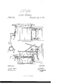
Be it known that I, J. A. LAFLER, of Albion, in the county of Orleans, and State of New York, have invented a new and useful Improvement in Brick-Machines; and I do hereby declare that the following is a full, clear, and exact description thereof, which will enable those skilled in the art to make and use the same, reference being had to the accompanying drawings, forming a part of this specification, in which- Figur'e 1 is a sectional side elevation of my invention, and
Figure 2 is a front view of the same. l
Figure 3 is a detail view, showingmy improved method of securing the Scrapers and knives tol the hollow cast-iron shaft.
Similar letters of reference indicate corresponding parts in all the figures. l
This invention relatesto certain new and useful improvements on J. A. Laflers patent brick-machine, No. 37,3448, whereby it is made adaptable for making either common or pressed brick, at will, and whereby its general eii'iciency and usefulness are much increased, as hereinafter set forth.
In the rear side of the press-box A, fig. 1, is a horizontal slot or opening, throughwhich works a slide, B,
which is operated,by a spur-wheel, C, pinion c, crank D, and connecting-rod d, the spur-wheel C being iixed on` the lower `end of the grind-sha`ft E. The object of this slide B is to close the upper side of the press-box A when the mould and clod-crusher F are forced up, so that the clay or mortar cannot return from the press-box to the grind-mill Gr, when pressure is applied to the said mould and clod-crusher for making pressed bricks.
When making common bricks, the slide B is not necessary, and can be thrown out of action by disengaging the connecting-rod el from the crank D. The working of :the machine can be changed from common to pressed brick, or vice versa, at any time within fifteen minutes. l y
For operating the swinging frame H by the grinding-power, a short crank-shaft,- z' I, g. 2, is placed over the grind-mill, and geared to'the main shaft E by gears J. The crank z' is loose on its shaft I, but i's made to engage with the shaft by means of a clutch-coupling, k,land connection.is made between the crank z and the swinging frame H through a, connecting-rod and chain, L Z, pulley M windlass-shaft m', and chains n n. The
clutch k is 'so constructed that it willjremain engaged onlyr when the crank z' is overcoming resistanee,.and when the crank is lifting Athe press-frame H the forward motion of the crank is resisted by the weight of said press'- frame, but as soon as the crank has passed its upper dead-point, the connection L Z passes to the front of the crank, so that the weight of the-press is thrown on the forward side of the crank, and as the weight of the press then pulls forward on the crank, instead of resisting its motion, the coupling k disengages, and the crank falls forward through half a revolution, letting the press-frame drop so that the press is opened immediately, and by this means time is saved in opening thc press. I
There is a concealed spiral spring in the coupling le, which holds the couplingdisengaged until closed byA theoperator by means of a hand-lever, N, which is donc always as soon as an empty mould has been brought under the clod-crusher F. v
The bed h, of the swinging frame H, is supported by cams r r, iig. 2, on the shaftltig. 1, and these shafts E R are supported by elastic cushions, P P, of rubber. These elastic supports allow a slight yielding of the bed L, when small-stone or' other obstructions protrude from the mould as it is being drawn but; and the cushions also keep thc'mould snug up tothe clod-crusher, so-'that they are struck off closely when'withdraw from under the clod-crusher. i i
I secure the scrapersS and knives s in the hollow cast-iron main shaft E,`iig. l, as follows: A hole or mortise is cast in the shaft for each knife or scraper, and I then form a hook, v, fig. 3, on the tang of each knife or scraper, and after introducing said hook` to the inside or chamber of the shaft, it is secured by driving v a key, t, behind the tang 'of the knife, so that the: hook v, on the front edge of the tang, engages with the shell of the shaft, as shown, and by this'meaus a very strong and cheap method of securing the knives is obtained.
By combining -the slide or throat-closer B and driving-devices with thismachine, it gives advantages that recommend themselves at once to brick-makers, as by this means the machine is capable of making common or pressed bricks; the machine being employed in making common bricks in fair weather, when they can be laid out on the yard to dry, while in wet weather, the'niachinel can be employed in making pressed bricks, as they can be haked" under shedding as soon as they come from the machine. And in this manner the machine can be kept steadily at work every day, and no losses occur by idleness duing Wet weather. i
Having thus described my invention, what I claim as new, and desire to secure by Letters Patent, is-
1. The self-relesing crank z', for operating the swinging press H, substantially in the manner and 'for the purpose set forth.
2. The method of s ,\e1.u'iny the scrapers and knives S s in the shaft E, namely, the hooked tangs v, in connection with keys t and mortised hollow shaft. E, substantially as and fol` the purpose set forth.
3. The combination of the swinging-press frame H, telescopic press-box F A, slide B, and driving-devices d D c C, working from the foot of the grind-shaft E, all constijucted and operating in the manner shown and for the puljpose described. i
The above specification of my invention signed by me, this 8th day of November; 1867.
' J. A. LAFLER.
Witnesses:
Cans. H. STEVENS, J. A. MORLEY.
Publications (1)
| Publication Number | Publication Date |
|---|---|
| US80976A true US80976A (en) | 1868-08-11 |
Family
ID=2150470
Family Applications (1)
| Application Number | Title | Priority Date | Filing Date |
|---|---|---|---|
| US80976D Expired - Lifetime US80976A (en) | Improved brick-machine |
Country Status (1)
| Country | Link |
|---|---|
| US (1) | US80976A (en) |
-
0
- US US80976D patent/US80976A/en not_active Expired - Lifetime
Similar Documents
| Publication | Publication Date | Title |
|---|---|---|
| US80976A (en) | Improved brick-machine | |
| US66723A (en) | Improved beiok machiie | |
| US30541A (en) | Brick-machine | |
| US196782A (en) | Improvement in brick-machines | |
| US105670A (en) | Improvement in the manufacture op soap | |
| US86732A (en) | Improved brick-machine | |
| US16449A (en) | Brick-machine | |
| US150924A (en) | williams | |
| US122714A (en) | Improvement in machines for making bricks and artificial stones | |
| US1169808A (en) | Brick-machine. | |
| US78343A (en) | Improved beicz-maceine | |
| US1106086A (en) | Cement-tile machine. | |
| US257608A (en) | Half to haeeiet waewood | |
| US76617A (en) | George b | |
| US64814A (en) | Improvement in cotton and eay-pkess | |
| US128787A (en) | Improvement in brick-machines | |
| US347136A (en) | tallcot | |
| US50088A (en) | Improvement in brick-presses | |
| US861144A (en) | Apparatus for molding blocks. | |
| US137460A (en) | Improvement in brick-machines | |
| US882249A (en) | Cement for concrete block mold. | |
| US309037A (en) | Brick machine | |
| US219196A (en) | Improvement in bretzel-machines | |
| US50097A (en) | Improved machine for making drain-tiles | |
| US93830A (en) | Improved tile-machine |