US809706A - Electric alternating-current machine. - Google Patents
Electric alternating-current machine. Download PDFInfo
- Publication number
- US809706A US809706A US26767805A US1905267678A US809706A US 809706 A US809706 A US 809706A US 26767805 A US26767805 A US 26767805A US 1905267678 A US1905267678 A US 1905267678A US 809706 A US809706 A US 809706A
- Authority
- US
- United States
- Prior art keywords
- armature
- slots
- poles
- pole
- current machine
- Prior art date
- Legal status (The legal status is an assumption and is not a legal conclusion. Google has not performed a legal analysis and makes no representation as to the accuracy of the status listed.)
- Expired - Lifetime
Links
Images
Classifications
-
- H—ELECTRICITY
- H02—GENERATION; CONVERSION OR DISTRIBUTION OF ELECTRIC POWER
- H02K—DYNAMO-ELECTRIC MACHINES
- H02K19/00—Synchronous motors or generators
- H02K19/02—Synchronous motors
- H02K19/10—Synchronous motors for multi-phase current
- H02K19/103—Motors having windings on the stator and a variable reluctance soft-iron rotor without windings
Definitions
- This invention relates to improvements in electric alternating-current machines, (generators, converters, or motors.)
- the simplest way of carrying out the invention is to place the poles of the magnetic field, and especially the pole-shoes or pole-plates of the same, in such manner with respect to theirrelative position that the distance between the middle of a pole-plate and the middle of the next poleplate on the one side practically becomes so much greater than the distance to the next pole-plate on the other side as the distance between the middles of adjacent slots of the armature.
- the difference in said distance may, though not so preferably, be made equal to three or live times said distances, and so on, between the middles of adjacent slots or holes.
- the same result may also be obtained by using one and the same pole-pitch and making every other pole so much thinner that the variations of the strength of the field, and thereby the variations of the curve of tension caused by the first-mentioned variations, occur with aphase difference of practically half a period at the poles of diti'erentpolarity.
- An alternating-current machine having the armature-Winding placed in more or less open slots in the armature-core, and every other distance between the middle lines at the pole-plates of the magnetic field so much greater than the intermediate distances as the distance between the middles of adjacent slots in the armature-core, substantially as and for the purpose set forth.
Landscapes
- Engineering & Computer Science (AREA)
- Power Engineering (AREA)
- Windings For Motors And Generators (AREA)
Description
PATENTED JAN. 9, 1906.
K. A. LINDSTROM. ELECTRIC ALTERNATING CURRENT MACHINE.
APPLICATION FILED JUNE 29, 1905.
AAA
42 I n f\ H n V U U U U Witnesses;
invenkm" Nam/L AMM VIM/24 m UNITED STATES PATENT OFFICE.
ELECTRIC ALTERNATlNG-CURRENT MACHINE.
Specification of Letters Patent.
Patented Jan. 9, 1906.
Application filed June 29, 1905. Serial No. 267,678.
To air/Z7 whom it may concern:
Be it known that I, KARL ARVID LINDsTRoM,
- a subject of the King of Sweden and Norway, and a resident of Vesteras, Sweden, have invented new and useful Improvements in Electric Alternating-Current Machines, of which the following is a specification.
This invention relates to improvements in electric alternating-current machines, (generators, converters, or motors.)
One of the most common grounds for the deviation of the curve of tension in an alternating current generator from the simple sinus-linee'. 6., that the curve of tension has so-called overtones is, as well known, the circumstance that the more or less open slots in the armature in which the winding of the latter is placed causes a discontinuity in the magnetic density of the air-gap, the said discontinuity in the relative movement of the armature and the magnetic field producing a periodical variation of the same density, and thus a corresponding variation of the induced electromotive force.
Trials have been made to obtain a suitable form of the pole-surface, so that the curve of the magnetic density in the air-gap, apart from the slots, should be of a simple sinus form, but in vain, since on account of the slots a deviation from the sinus-curve or an overtone in the same has always resulted. For several important reasons it is, however, in the most cases desirable to obviate such overtones, and the present invention relates to a device for that purpose. If, as heretofore generally has been the case, the onehalf-number of the conductors of the armature,which are connected in series in one and the same circuit, are under the south poles, simultaneously as the other half-number occupy the same position in relation to the north poles (though with reversed direction of current) the overtones produced by the slots in the both halves add themselves together. In order to obviate the said inconvenience, the poles of different polarity of the magnetic field are according to the present invention arranged in such manner in relation to the halves of the windings of the armature that the overtones induced in the one half will be practically displaced half a period in relation to the overtones induced in the other half, whereby the said overtones will nullify each other, so that the curve of tension will be free from variations of the said kind. The simplest way of carrying out the invention is to place the poles of the magnetic field, and especially the pole-shoes or pole-plates of the same, in such manner with respect to theirrelative position that the distance between the middle of a pole-plate and the middle of the next poleplate on the one side practically becomes so much greater than the distance to the next pole-plate on the other side as the distance between the middles of adjacent slots of the armature. Obviously the difference in said distance may, though not so preferably, be made equal to three or live times said distances, and so on, between the middles of adjacent slots or holes. The same result may also be obtained by using one and the same pole-pitch and making every other pole so much thinner that the variations of the strength of the field, and thereby the variations of the curve of tension caused by the first-mentioned variations, occur with aphase difference of practically half a period at the poles of diti'erentpolarity. Finally, it is possible to effect a nullifying of the waves of tension of higher order by giving the poleplates or the slots of the armature-core an oblique direction.
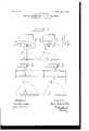
My invention is diagrammatically illus trated in the accompanying drawings, in which Figure 1 shows a developed part of an armature, corresponding field-poles, and curves representing the electromotive force; and Figs. 2 and 3 show other such curves.
Referring to the drawings, Fig. 1 shows some poles N S and a part of the armature having the teeth T and the slots T between them. The armature is provided with six slots for each pole. In two of the said slots situated in like manner in relation to adjacent poles are shown conductors b and Z), which are series connected in one and the same circuit. In each of the said conductors is induced an electromotive force which would be represented by the curves F and F, respectively, (the fundamental wave,) if the armature had no slots and the conductors be placed on the even surface of the armature. On account of the slots and the discontinuity of the magnetic density of the air-gap caused by the same an electromotive force of higher order (an overtone) H and H, respectively, is induced, which adds itself to the fundamental wave. The resulting curve of the electromotive force thus becomes the sum of both the said curves. (Not shown in Fig. 1.) The said two conductors are under the influence of poles of difi erent polarity, and on account thereof the electromotive forces have different signs; but on account of the series connection the electromotive forces of the two conductors add themselves together both with respect to the fundamental waves, the resultant of which may be represented by the curve F in Fig. 2, and the overtones, the resultant of which may be represented by the curve H in Fig. 2. If 'now, as an application of my invention, the pole-shoes of all the poles indicated by N (the north poles) be displaced to the right a distance corresponding to one-quarter of the distance between the middle points of two adjacent slots and the pole'shoes of all the poles indicated by S (the south pole) be displaced a corresponding distance to the left, such displacements being indicated by dotted lines in Fig. 1, so that the distance between the middle of a pole-shoe and the middle of the next poleshoe on the one side becomes as much smaller than the distance to the middle of the poleshoe on the other side as the Whole distance between the middle-points of two adjacent slots, this will have but little influence on the fundamental waves (F in Fig. 3) of the two conductors. On the contrary, the overtones will be displaced in relation to each other onehalf of their period and will therefore practically fully neutralize each other. The sum of them will be almost like null, as shown by the curve H in Fig. 3. The curve of electromotive force resulting from the curves F and H will therefore obtain approximately the same clean form as the fundamental wave.
Having now described my invention, what I claim is- 1. An alternating-current machine having the armature-winding placed in more or less open slots in the armature-core, and poles of the magnetic field so placed in relation to the two halves of an armature-winding that the waves of tension of higher order, the socalled overtones, induced by certain of the poles in the armature-circuit on account of the discontinuity of the magnetic field caused by the slots of the armature-core, are displaced practically half a period in relation to the corresponding overtones induced by the other poles, substantially as and for the purpose set forth.
2. An alternating-current machine having the armature-Winding placed in more or less open slots in the armature-core, and every other distance between the middle lines at the pole-plates of the magnetic field so much greater than the intermediate distances as the distance between the middles of adjacent slots in the armature-core, substantially as and for the purpose set forth.
In testimony whereof I have signed my name to this specification in the presence of two subscribing witnesses.
KARL ARVID LINDSTROM.
Witnesses:
GERDA LINDKvIs'r, JOHN DELMAR.
Priority Applications (1)
| Application Number | Priority Date | Filing Date | Title |
|---|---|---|---|
| US26767805A US809706A (en) | 1905-06-29 | 1905-06-29 | Electric alternating-current machine. |
Applications Claiming Priority (1)
| Application Number | Priority Date | Filing Date | Title |
|---|---|---|---|
| US26767805A US809706A (en) | 1905-06-29 | 1905-06-29 | Electric alternating-current machine. |
Publications (1)
| Publication Number | Publication Date |
|---|---|
| US809706A true US809706A (en) | 1906-01-09 |
Family
ID=2878187
Family Applications (1)
| Application Number | Title | Priority Date | Filing Date |
|---|---|---|---|
| US26767805A Expired - Lifetime US809706A (en) | 1905-06-29 | 1905-06-29 | Electric alternating-current machine. |
Country Status (1)
| Country | Link |
|---|---|
| US (1) | US809706A (en) |
Cited By (2)
| Publication number | Priority date | Publication date | Assignee | Title |
|---|---|---|---|---|
| WO1986001652A1 (en) | 1984-08-31 | 1986-03-13 | Ab Elmo | A synchronous servomotor |
| EP3247023A1 (en) * | 2016-05-18 | 2017-11-22 | Siemens Aktiengesellschaft | Alternating current generator and system, and installation for generating a three-phase alternating voltage |
-
1905
- 1905-06-29 US US26767805A patent/US809706A/en not_active Expired - Lifetime
Cited By (4)
| Publication number | Priority date | Publication date | Assignee | Title |
|---|---|---|---|---|
| WO1986001652A1 (en) | 1984-08-31 | 1986-03-13 | Ab Elmo | A synchronous servomotor |
| JPS62500140A (en) * | 1984-08-31 | 1987-01-16 | エルモ・インデュストリエル・アクチボラゲット | synchronous servo motor |
| EP3247023A1 (en) * | 2016-05-18 | 2017-11-22 | Siemens Aktiengesellschaft | Alternating current generator and system, and installation for generating a three-phase alternating voltage |
| WO2017198409A1 (en) * | 2016-05-18 | 2017-11-23 | Siemens Aktiengesellschaft | System and installation for generating a three-phase alternating voltage |
Similar Documents
| Publication | Publication Date | Title |
|---|---|---|
| Martin | The inventions, researches and writings of Nikola Tesla | |
| US3041486A (en) | Variable reluctance device | |
| US382279A (en) | Electro—Magnetic Motor | |
| US809706A (en) | Electric alternating-current machine. | |
| US1581876A (en) | Dynamo-electric machine | |
| US1361546A (en) | Dynamo-electric machine | |
| US2054678A (en) | Direct-current motor-inductor alternator | |
| US433758A (en) | Hungary | |
| US589674A (en) | Half to iiexry fairbanks | |
| US567423A (en) | thuey | |
| US598657A (en) | William beedie esson | |
| US469281A (en) | Johannes sohlman | |
| US842963A (en) | Dynamo-electric machine. | |
| US3225286A (en) | Voltage and frequency regulator for a motor-generator inverter | |
| US487796A (en) | Nikola tesla | |
| US1800028A (en) | Single-unit frequency changer | |
| US432655A (en) | Dynamo-electric machine | |
| US1092420A (en) | Dynamo-electric machine. | |
| US664396A (en) | Dynamo-electric machine. | |
| US1967159A (en) | Rotary apparatus for converting alternating electric currents to direct electric currents and vice versa | |
| US560591A (en) | Robert lundell | |
| US327797A (en) | Electric Motor | |
| US564702A (en) | lamme | |
| US551712A (en) | Hampton | |
| US745508A (en) | Means for producing alternating currents of low periodicity. |