US809705A - Combined railway draw-head and air coupling. - Google Patents
Combined railway draw-head and air coupling. Download PDFInfo
- Publication number
- US809705A US809705A US23373904A US1904233739A US809705A US 809705 A US809705 A US 809705A US 23373904 A US23373904 A US 23373904A US 1904233739 A US1904233739 A US 1904233739A US 809705 A US809705 A US 809705A
- Authority
- US
- United States
- Prior art keywords
- draw
- head
- aperture
- coupling
- chamber
- Prior art date
- Legal status (The legal status is an assumption and is not a legal conclusion. Google has not performed a legal analysis and makes no representation as to the accuracy of the status listed.)
- Expired - Lifetime
Links
- 238000010168 coupling process Methods 0.000 title description 10
- 238000005859 coupling reaction Methods 0.000 title description 10
- 230000008878 coupling Effects 0.000 title description 9
- 210000002445 nipple Anatomy 0.000 description 18
- 241001474033 Acar Species 0.000 description 1
- 238000005266 casting Methods 0.000 description 1
- 239000012530 fluid Substances 0.000 description 1
- 239000012858 resilient material Substances 0.000 description 1
Images
Classifications
-
- B—PERFORMING OPERATIONS; TRANSPORTING
- B61—RAILWAYS
- B61G—COUPLINGS; DRAUGHT AND BUFFING APPLIANCES
- B61G5/00—Couplings for special purposes not otherwise provided for
- B61G5/06—Couplings for special purposes not otherwise provided for for, or combined with, couplings or connectors for fluid conduits or electric cables
- B61G5/08—Couplings for special purposes not otherwise provided for for, or combined with, couplings or connectors for fluid conduits or electric cables for fluid conduits
Definitions
- Serial No. 233,739- a This invention relates more particularly to that class of air-couplers or similar devices which are designed to couple the airor steam pipes of acar automatically with the coupling of the cars proper, such an apparatus being shown in Patent No. 7%),900, granted to me January 19, 1904.
- the present invention provides means for automatically closing the orifices or pipes of the couplers through which such connections of the train-pipes are made when the draw-heads are disconnected. I prefer to use this improvement in connection with draw-heads of the character set forth in said patent and for this reason have illustrated this improvement as applied to such drawheads.
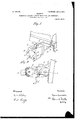
- Figure 1 is a perspective view, partly broken, of a car end provided with a draw-bar and coupler embodyin my invention.
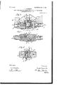
- Fig. 2 is a top plan view of the same, showing the draw-head coupled with a like draw-head and both flexed on the draw-bars under lateral strain, as in rounding a curve.
- Fig. 3 is a section taken on line 3 3 of Fig. 2 and showing the pins lifted.
- Fig. 4: is a central horizontal section taken on Fig. 3.
- Fig. 5 is a section on line 5 5 of Fig. 3.
- A indicates a draw-bar adapted to be engaged with draftrigging of any preferred kind in the usual or any desired manner and having an axial aperture therein, as shown in Figs. 3 and 4.
- N ear the outer end of said draw-bar is provided an upwardly-extending transverse shoulder (0, adapted when the car is coupled to communicate a part of the bufiing stress to the end sill B of the car in the usual manner.
- the outer end of the draw-bar is enlarged and is recessed and a horizontally-extending shelf a which is rounded at its outer end, forms the bottom of said recess, and a corresponding forwardlyextended rounded plate or shelf 0, is provided above said recess.
- a rearwardly-directed tail C integral with the rear end of the draw-head and having less thickness than the height of the recess in the draw-bar, is secured to said draw-bar by means of the pivot-pin D. This pin ex' tends through said tail and through the plates a and a and may be secured below the drawbar by means of a cotter-pin or the like, if desired.
- a strong leaf-spring (Z engages in a slot at the rear end of the tail C and extends longitudinally of the aperture in the draw-bar and at its inner end engages in a socket at the inner end of said aperture, so that when the draw-head is flexed on the drawbar tension is brought on said spring.
- the draw-heads comprise each a casting provided on its outer end with an integral forwardlydirected arm E, having an integral inwardly-hooked knuckle e. Said draw-head is also provided in its outer end near the opposite side from said arm with a recess E.
- the arms E and recesses E in said draw-heads are so disposed that when the draw-heads are broughttogether in coupling the arm and knuckle of each draw-head engage in the recess' of the other.
- a coupling-pin F having a downwardly rounded or inclined lower end, extends through and fits closely in an aperture in the top of each draw-head, into and partly through each of said recesses, and is provided with a longitudinal groove in one side thereof, into which extends the end pin or dowel secured in the draw-head.
- the upper surface of each of the knuckles is beveled or inclined outwardly and downwardly, as shown in Figs. 1 and 3, so that when the draw-heads are brought together in coupling relation the impact of said knuckles on the pins. throws the same upwardly and permitting the passage of the knuckles beneath the same and permitting the pins to drop behind the knuckles, as shown' in Fig.
- said pins are provided each with integral outwardly-extending fiat arms 5 f f of which the arms f are of a sufiicient length and so positioned that when the drawheads are brought together in coupling said arms f extend beneath and in contact with the arms f of the corresponding draw-head, as shown in Fig. 2, so that either upward or downward movement of either produces cor-j responding movement in the other.
- crank Gris provided on'the car end, the outer end of which extends into position to be conveniently engaged by the brakeman and the inner end of which extends forwardly over the coupling-pin, and a chain 9 connects the same.
- a transverse chamber H is provided in the lower part of each draw-head, from which a nipple it or other connection adapted to permit a hose it to be coupled therewith extends laterally from the draw-head.
- an apertured conical nipple or pipe 7L2 communicating with said chamber, extends from the front end of the draw-head below the knuckle e, and an aperture extends through the end of the drawhead opening into said chamber near the opposite side of the draw-head and is provided with a bushing if, of rubber or other resilient material.
- Said conical nipples and the apertures at the outer ends of the respective drawheads are so disposed as to register exactly when the draw-heads are brought together, as shown in Fig. 5, thus forming an air-tight connection through which the chambers in the respective draw-head communicate, providing when the train-pipe hose h is connected with the nipples h a continuous passage through the draw-head, as shown in Fig. 5, for the passage of air, steam, or the like, as indicated by the arrows.
- an automatic checkvalve device Inorder to prevent the escape of air or steam from the end of the draw-head or the hose-coupling when the draw-heads are uncoupled, I prefer to use an automatic checkvalve device.
- a device is illustrated particularly in Figs. 3 and 5 of the drawings.
- At either end of the chamber H is a recess having a curved bottom, and in said recesses are located balls if. These balls act as valves to close the inner end of the nipple-aperture or to close the opening through the rubber bushing if when the draw-heads are uncoupled.
- the outer or projecting ends of the nipples or connecting pipes k are provided with slots or openings 72.".
- Inadraw-head or the like provided with chambers connected with the train-pipes, the combination of an aperture leading from said chamber, said aperture being provided with a rubber bushing, a nipple leading from said chamber having slots or openings in its outer end, ball-valves in said chamber adapted to close said aperture and said nipple, a corresponding draw-head provided with suitablydisposed similar apertures and projecting nipples, the arrangement being such that when the draw-heads are connected, the projecting nipples will unseat the balls closing the apertures in the opposite draw-heads.
- a draw-head having in its bottom a transverse chamber,a pipe connected with the chamber, and a projection extending outwardly from the draw-head and provided with an aperture communicating with said chamber, said projection adapted to extend into an aperture in a corresponding draw-head and communicating with a like chamber therein, and valves adapted to close said apertures when the drawheads are uncoupled.
Landscapes
- Engineering & Computer Science (AREA)
- Mechanical Engineering (AREA)
- Quick-Acting Or Multi-Walled Pipe Joints (AREA)
Description
No. 809,705. v PATENTED JAN. 9, 1906. L. LECOMPTE.
, COMBINED RAILWAY DRAW HEAD ANDAIR COUPLING.
APPLIOATION FILED NOV. 21, 1904..
2 SHEETS-SHEET 1.
W'nmesses: \mm xmv,
21 bums Lgcgmvr PATENTED JAN. 9, 1906. L. LEGOMPTE.
COMBINED RAILWAY DRAW HEAD AND AIR COUPLING.
APPLICATION FILED NOV.'21, 1904.
v 2 SHEETS-SHEET 2. 1%;
Whwzsses:
\mxmmov, n 1?. am 7 Louis Legomk e". whm mym WsisB-g i TE STATES- PATENT CFFICI J.
LOUIS LECOMPTE, OFCHICAGO, ILLINOIS.
COMBINED RAILWAY DRAW-HEAD AND AIR COUPLING.
Specification of Letters Patent.
Patented Jan. 9, 1906.
Application filed November 21, 1904. Serial No. 233,739- a This invention relates more particularly to that class of air-couplers or similar devices which are designed to couple the airor steam pipes of acar automatically with the coupling of the cars proper, such an apparatus being shown in Patent No. 7%),900, granted to me January 19, 1904. The present invention provides means for automatically closing the orifices or pipes of the couplers through which such connections of the train-pipes are made when the draw-heads are disconnected. I prefer to use this improvement in connection with draw-heads of the character set forth in said patent and for this reason have illustrated this improvement as applied to such drawheads.
In the accompanying drawings, Figure 1 is a perspective view, partly broken, of a car end provided with a draw-bar and coupler embodyin my invention. Fig. 2 is a top plan view of the same, showing the draw-head coupled with a like draw-head and both flexed on the draw-bars under lateral strain, as in rounding a curve. Fig. 3 is a section taken on line 3 3 of Fig. 2 and showing the pins lifted. Fig. 4: is a central horizontal section taken on Fig. 3. Fig. 5 is a section on line 5 5 of Fig. 3.
As shown in the drawings, A indicates a draw-bar adapted to be engaged with draftrigging of any preferred kind in the usual or any desired manner and having an axial aperture therein, as shown in Figs. 3 and 4. N ear the outer end of said draw-bar is provided an upwardly-extending transverse shoulder (0, adapted when the car is coupled to communicate a part of the bufiing stress to the end sill B of the car in the usual manner. The outer end of the draw-bar is enlarged and is recessed and a horizontally-extending shelf a which is rounded at its outer end, forms the bottom of said recess, and a corresponding forwardlyextended rounded plate or shelf 0, is provided above said recess. Said plates (2M as shown,
fit in corresponding complemcntal curved surfaces at the rear end of the draw-head or coupler C, which, as shown, is provided with the complementally-curved surfaces 0 c, which receive the rounded ends of said plates 0 and a. A rearwardly-directed tail C, integral with the rear end of the draw-head and having less thickness than the height of the recess in the draw-bar, is secured to said draw-bar by means of the pivot-pin D. This pin ex' tends through said tail and through the plates a and a and may be secured below the drawbar by means of a cotter-pin or the like, if desired. I As shown, a strong leaf-spring (Z engages in a slot at the rear end of the tail C and extends longitudinally of the aperture in the draw-bar and at its inner end engages in a socket at the inner end of said aperture, so that when the draw-head is flexed on the drawbar tension is brought on said spring.
The draw-heads comprise each a casting provided on its outer end with an integral forwardlydirected arm E, having an integral inwardly-hooked knuckle e. Said draw-head is also provided in its outer end near the opposite side from said arm with a recess E. The arms E and recesses E in said draw-heads are so disposed that when the draw-heads are broughttogether in coupling the arm and knuckle of each draw-head engage in the recess' of the other. As shown, a coupling-pin F, having a downwardly rounded or inclined lower end, extends through and fits closely in an aperture in the top of each draw-head, into and partly through each of said recesses, and is provided with a longitudinal groove in one side thereof, into which extends the end pin or dowel secured in the draw-head. The upper surface of each of the knuckles is beveled or inclined outwardly and downwardly, as shown in Figs. 1 and 3, so that when the draw-heads are brought together in coupling relation the impact of said knuckles on the pins. throws the same upwardly and permitting the passage of the knuckles beneath the same and permitting the pins to drop behind the knuckles, as shown' in Fig. 4, presenting a square flat draft-surface for the knuckle, so that when the draw-heads are brought together the said arms and integral knuckles bring the ends of the same into register, holding the same firmly and unyieldingly locked together. Inasmuch as each of the pins F must rise to permit the draw-heads to couple,
means have been provided whereby either pin when lifted will lift the other simultaneously. For this purpose said pins are provided each with integral outwardly-extending fiat arms 5 f f of which the arms f are of a sufiicient length and so positioned that when the drawheads are brought together in coupling said arms f extend beneath and in contact with the arms f of the corresponding draw-head, as shown in Fig. 2, so that either upward or downward movement of either produces cor-j responding movement in the other. This is important in uncoupling, inasmuch as the pins must be lifted simultaneously, and for the purpose of facilitating uncoupling without necessitating the brakeman passing between the cars a crank Gris provided on'the car end, the outer end of which extends into position to be conveniently engaged by the brakeman and the inner end of which extends forwardly over the coupling-pin, and a chain 9 connects the same.
To enable the coupling of the draw-head to simultaneously couple the train-pipes, a transverse chamber H is provided in the lower part of each draw-head, from which a nipple it or other connection adapted to permit a hose it to be coupled therewith extends laterally from the draw-head. As shown, an apertured conical nipple or pipe 7L2, communicating with said chamber, extends from the front end of the draw-head below the knuckle e, and an aperture extends through the end of the drawhead opening into said chamber near the opposite side of the draw-head and is provided with a bushing if, of rubber or other resilient material. Said conical nipples and the apertures at the outer ends of the respective drawheads are so disposed as to register exactly when the draw-heads are brought together, as shown in Fig. 5, thus forming an air-tight connection through which the chambers in the respective draw-head communicate, providing when the train-pipe hose h is connected with the nipples h a continuous passage through the draw-head, as shown in Fig. 5, for the passage of air, steam, or the like, as indicated by the arrows.
Inorder to prevent the escape of air or steam from the end of the draw-head or the hose-coupling when the draw-heads are uncoupled, I prefer to use an automatic checkvalve device. Such a device is illustrated particularly in Figs. 3 and 5 of the drawings. At either end of the chamber H is a recess having a curved bottom, and in said recesses are located balls if. These balls act as valves to close the inner end of the nipple-aperture or to close the opening through the rubber bushing if when the draw-heads are uncoupled. The outer or projecting ends of the nipples or connecting pipes k are provided with slots or openings 72.". When the draw-heads are coupled, the projecting ends of the nipples if extend sufiicientl y through the bushings 72/3 to dislodge the corresponding ball it. When in this position, the air or steam, which is admitted into one draw-head-as, for instance, shown entering the top pipe 71/ in Fig 5will pass through the slots or openings it in the lower nipple and will raise the opposite ball if from its seat and pass out through the lower pipe it. The reverse operation will of course occur if the air or steam is admitted in the opposite direction. It is evident that other check-valves could be used to perform the functions of the valves justdescribed, and I do not wish to limit myself to this particular form of valve apparatus.
WhatI claim, and desire to secure by Letters Patent, is
1. In an air or steam pipe coupling device, the combination with a suitably-chambered head, of an aperture in said head, a checkvalve for said aperture, a projecting nipple from said chamber, and a check-valve for said nipple, said nipple being adapted to enter the aperture of a corresponding head to unseat the check-valve in said aperture.
2. The combination with a chambered drawhead or the like, of an aperture leading from said chamber, a pipe or nipple extending from said chamber, slots or the like in the outer end of said nipple, a ball-valve for closing said aperture, a second ball-valve for closing the opening through said nipple, the arrangement being such that when I said device is brought into, cooperative relation with a corresponding device, one or more of the ballvalves will be opened to admit the passage of a fluid.
' 3. Inadraw-head or the like, provided with chambers connected with the train-pipes, the combination of an aperture leading from said chamber, said aperture being provided with a rubber bushing, a nipple leading from said chamber having slots or openings in its outer end, ball-valves in said chamber adapted to close said aperture and said nipple, a corresponding draw-head provided with suitablydisposed similar apertures and projecting nipples, the arrangement being such that when the draw-heads are connected, the projecting nipples will unseat the balls closing the apertures in the opposite draw-heads.
4. A draw-head having in its bottom a transverse chamber,a pipe connected with the chamber, and a projection extending outwardly from the draw-head and provided with an aperture communicating with said chamber, said projection adapted to extend into an aperture in a corresponding draw-head and communicating with a like chamber therein, and valves adapted to close said apertures when the drawheads are uncoupled.
5. An automatic car and hose-pipe coupling,
valves for closingsaid opening and said nipple, and hose-pipe connections on each coup- IO ler opening Into the chamber therein.
LOUIS LECOMPTE.
lVitnesses:
PHILIP JOHNS, M. C. SIKTBERG.
Priority Applications (1)
| Application Number | Priority Date | Filing Date | Title |
|---|---|---|---|
| US23373904A US809705A (en) | 1904-11-21 | 1904-11-21 | Combined railway draw-head and air coupling. |
Applications Claiming Priority (1)
| Application Number | Priority Date | Filing Date | Title |
|---|---|---|---|
| US23373904A US809705A (en) | 1904-11-21 | 1904-11-21 | Combined railway draw-head and air coupling. |
Publications (1)
| Publication Number | Publication Date |
|---|---|
| US809705A true US809705A (en) | 1906-01-09 |
Family
ID=2878186
Family Applications (1)
| Application Number | Title | Priority Date | Filing Date |
|---|---|---|---|
| US23373904A Expired - Lifetime US809705A (en) | 1904-11-21 | 1904-11-21 | Combined railway draw-head and air coupling. |
Country Status (1)
| Country | Link |
|---|---|
| US (1) | US809705A (en) |
-
1904
- 1904-11-21 US US23373904A patent/US809705A/en not_active Expired - Lifetime
Similar Documents
| Publication | Publication Date | Title |
|---|---|---|
| US809705A (en) | Combined railway draw-head and air coupling. | |
| US749900A (en) | Combined railway draw-head and air-coupling | |
| US593119A (en) | Office | |
| US511427A (en) | Gar-coupling | |
| US308011A (en) | Car-coupling | |
| US702497A (en) | Fluid-pressure coupling. | |
| US482382A (en) | Combined air-brake and car-coupling | |
| US833702A (en) | Automatic fluid-coupling. | |
| US494630A (en) | Car-coupling | |
| US158541A (en) | Improvement in car-couplings | |
| US864487A (en) | Air-coupling. | |
| US619559A (en) | pritchett | |
| US1187938A (en) | Car and automatic air-brake coupling. | |
| US426317A (en) | Coupling for electric cars | |
| US286207A (en) | Car-coupling | |
| US402212A (en) | Car-coupling | |
| US219206A (en) | Improvement in car-couplings | |
| US545305A (en) | Automatic car-coupling | |
| US472103A (en) | E jtoftms petebs co | |
| US851316A (en) | Automatic air-signal, air-brake, and steam coupling. | |
| US411216A (en) | Tereitory | |
| US415449A (en) | Car-coupling | |
| US454417A (en) | Signoe of two-thirds to john darrall and william reese | |
| US546864A (en) | Car-coupling | |
| US474806A (en) | William r betham |