US80968A - jones - Google Patents
jones Download PDFInfo
- Publication number
- US80968A US80968A US80968DA US80968A US 80968 A US80968 A US 80968A US 80968D A US80968D A US 80968DA US 80968 A US80968 A US 80968A
- Authority
- US
- United States
- Prior art keywords
- gears
- shaft
- wheel
- clutch
- gear
- Prior art date
- Legal status (The legal status is an assumption and is not a legal conclusion. Google has not performed a legal analysis and makes no representation as to the accuracy of the status listed.)
- Expired - Lifetime
Links
- 230000013011 mating Effects 0.000 description 1
Images
Classifications
-
- F—MECHANICAL ENGINEERING; LIGHTING; HEATING; WEAPONS; BLASTING
- F16—ENGINEERING ELEMENTS AND UNITS; GENERAL MEASURES FOR PRODUCING AND MAINTAINING EFFECTIVE FUNCTIONING OF MACHINES OR INSTALLATIONS; THERMAL INSULATION IN GENERAL
- F16H—GEARING
- F16H57/00—General details of gearing
- F16H57/08—General details of gearing of gearings with members having orbital motion
- F16H57/082—Planet carriers
Definitions
- FIG. 2 is a detail of the clutch.
- Figure 3 is a face view of the gears.
- My invention consists in 'the combination of a large circle with internal gear, with several smaller gears matehinginto said larger gear, operated by a shaft.
- It also consists of a method of operating or revolving the drum or shaft with varying degrees of speed and power.
- A shows a. large internal gear; a b e Z e, smaller gears, matching into the larger gear ⁇ A.
- f is a geared wheel around theshaft C.
- D is a drum.
- E is a clutch, to change the application of the power from the shaft C to the outer Aedge or the periphery of the face-plate F. y
- Theshaft and wheel are supported by any convenient frame, as L.
Landscapes
- Engineering & Computer Science (AREA)
- General Engineering & Computer Science (AREA)
- Mechanical Engineering (AREA)
- Structure Of Transmissions (AREA)
Description
@auch gisten gstmt @ffice W. O. JONES, OF PORTLAND, MAINE.
Letters Patent No. 80,968, dated August 11, 1868 IMPROVEMENT IN HOISTING-GEAR.
titte ngstlich referrer in it tigen tetters ntnrt mit mating raft uf tte sans.
ToALL wHoM 1T MAY coNoERN:
Be it known that I, W. O. JONES, of Portland, in the county of Cumberland, and State of Maine, have invented'a new and useful Improved Hoisting-Gear; and I hereby declare the following to be a full, clear, and
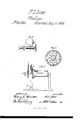
exact description thereof, which will enable others to make and use my invention, reference being had. to the accompanying drawings,.forming a part of this specification, in which- Figure 1 is a side elevation of my invention.
Figure 2 is a detail of the clutch.
Figure 3 is a face view of the gears. Y
My invention consists in 'the combination of a large circle with internal gear, with several smaller gears matehinginto said larger gear, operated by a shaft.
It also consists of a method of operating or revolving the drum or shaft with varying degrees of speed and power.
A shows a. large internal gear; a b e Z e, smaller gears, matching into the larger gear` A. f is a geared wheel around theshaft C. D is a drum. E is a clutch, to change the application of the power from the shaft C to the outer Aedge or the periphery of the face-plate F. y
Theshaft and wheel are supported by any convenient frame, as L.
H is a large wheel, tol which power'may be applied. The sliding part of the clutch is seen at l1., thexed parts at'z'j. When the projection of the sliding part h is entered in the recess for it in z', then the revolution of thelarge wheel H simply revolves the shaft C, whichshaft turns the drum D, and with it the face-plate F, and this face-plate carries the two gears e and c, which impart motion tof, and thus move al1 tle small gears. Underthese circumstances, the drum D revolves with the same speed as the wheel H.
When the clutch is entered into the recesses in j, then it revolves the wheel f, which also revolves the fixed gears e e, which have shafts m on the face-plate F. Thus, when the clutch is inserted at the recesses'in j, the drum D is turned by force applied near the circumfereneeof F, which greatly increases the power, or the ease with which D is turned, although, of course, the movement of D is then slower thanl when movedbythe clutch inserted at i. By means of rods 'n n', when one end of the sliding part h is inserted, the other is withdrawn. When 'unconnected with either i or j, the wheel H is free on the shaft C. i
All of the small gears, both those that are fixed on shafts and those that revolve freely, serve as friction-.. rollers for the gearfof the shaft C. The said gear fis free on the shaft C.
Thus a machine is supplied 'whichcan operate with greater or less speed, when desired, and with greater or less power. Y
-I do not claim the gears a b, the., broadly, fo r they have been before applied to the inner periphery lof a 'larger gear.
Instead of eand c, or any other two of the'smaller gears, only one may be'furnishcdjvith the shafts, asm and k, or all may have them, as desired.
I do not, of course, claim .a train of gears arranged around a central shaft, which also has a gear fixed upon it, but my invention applies tothe particular arrangement shown and described herein.
' The patent of Jacob Edson, No. 70,180, October 29, 1867, is different from mine, land I donot claim the specied arrangement of a lever-pawl, a brake, a windlass-barrcl, a brake-pulley, ratchet, shaft, and train of gears. on the inner side of a ratchet revolving on a shaft.
Neither do I claim the combination of a screw-arm with a brake and lever-pawl, for the purplose'of causing the brake to act with friction on a brake-pulley. This combination is different from mine, and its method of 'operation is not the same.
I have already specified my invention to be applicable to a variety lof uses, such as, for example, twisting or laying up rope, Sac., by so arranging the gears as to obtain the necessary speed of revolution of the drum,
It is obvious that my invention may be applied to a variety of uses.
eoes 2 What I do claim as my invention, and desire to secure by Letters Patent, is-
1. The combination of the geared wheel f with the gears c and e, having shafts k and 'm on the face-plate F, and when the elutch z is inserted at the recesses in j, substantially as and for the purposes set forth.
2. The combination of the clutch 7L z', on shaft C, with the gearsa b c d e, andgear f,'as and for the purposes set forth.
3. The combination of the small gears a b c d e, both fixed andk free, when serving in connection with f, not only as levers to revolve the faee-plate F, as isthe oase with the gears having shafts, but also as frictioniollers for the shaft C, substantially as herein set forth.
, W. 0. JONES.
Witnesses:
WM. HENRY CLIFFORD, HENRY C. HOUSTON.
Publications (1)
| Publication Number | Publication Date |
|---|---|
| US80968A true US80968A (en) | 1868-08-11 |
Family
ID=2150462
Family Applications (1)
| Application Number | Title | Priority Date | Filing Date |
|---|---|---|---|
| US80968D Expired - Lifetime US80968A (en) | jones |
Country Status (1)
| Country | Link |
|---|---|
| US (1) | US80968A (en) |
Cited By (2)
| Publication number | Priority date | Publication date | Assignee | Title |
|---|---|---|---|---|
| US20080103016A1 (en) * | 2006-10-25 | 2008-05-01 | Remy Inc. | Modular planetary gear assembly and drive |
| US20180369697A1 (en) * | 2012-10-03 | 2018-12-27 | Gree, Inc. | Method of synchronizing online game, and server device |
-
0
- US US80968D patent/US80968A/en not_active Expired - Lifetime
Cited By (3)
| Publication number | Priority date | Publication date | Assignee | Title |
|---|---|---|---|---|
| US20080103016A1 (en) * | 2006-10-25 | 2008-05-01 | Remy Inc. | Modular planetary gear assembly and drive |
| US7828687B2 (en) | 2006-10-25 | 2010-11-09 | Remy Technologies, L.L.C. | Modular planetary gear assembly and drive |
| US20180369697A1 (en) * | 2012-10-03 | 2018-12-27 | Gree, Inc. | Method of synchronizing online game, and server device |
Similar Documents
| Publication | Publication Date | Title |
|---|---|---|
| US80968A (en) | jones | |
| US2209122A (en) | Control device with adjustable reversibility | |
| US151472A (en) | Improvement in rotary engines | |
| US81329A (en) | Improved mechanical movement | |
| US787830A (en) | Variable-speed gearing. | |
| US259572A (en) | Christian e | |
| US75495A (en) | Improvement in device foe converting rotary into reciprocating motion | |
| US636969A (en) | Motion-reversing mechanism. | |
| US202430A (en) | Improvement in governors | |
| US331988A (en) | Nail-machine | |
| US1043176A (en) | Transmission-gear. | |
| US114414A (en) | Improvement in bridge-gates | |
| US1151079A (en) | Clutch mechanism. | |
| US735068A (en) | Speed-changing mechanism. | |
| US300894A (en) | Motor | |
| US100769A (en) | Improvement in hoistingkmachines | |
| US241818A (en) | Windlass for vessels of navigation | |
| US1516831A (en) | Differential mechanism | |
| US256627A (en) | Device for transmitting motion | |
| US315239A (en) | Friction-drum | |
| US88214A (en) | Improved bolt-heading machine | |
| US65483A (en) | Improvement in rotary steam engines | |
| US868797A (en) | Transmission mechanism. | |
| US1187340A (en) | Transmission-gearing for motor-vehicles. | |
| US91048A (en) | Henry shutt-s |