US809676A - Sickle. - Google Patents
Sickle. Download PDFInfo
- Publication number
- US809676A US809676A US25749105A US1905257491A US809676A US 809676 A US809676 A US 809676A US 25749105 A US25749105 A US 25749105A US 1905257491 A US1905257491 A US 1905257491A US 809676 A US809676 A US 809676A
- Authority
- US
- United States
- Prior art keywords
- sickle
- shaft
- blade
- guides
- machine
- Prior art date
- Legal status (The legal status is an assumption and is not a legal conclusion. Google has not performed a legal analysis and makes no representation as to the accuracy of the status listed.)
- Expired - Lifetime
Links
- 238000010008 shearing Methods 0.000 description 2
- 229910000831 Steel Inorganic materials 0.000 description 1
- 239000011230 binding agent Substances 0.000 description 1
- 239000010959 steel Substances 0.000 description 1
- 239000010902 straw Substances 0.000 description 1
- 238000004804 winding Methods 0.000 description 1
Images

Classifications
-
- A—HUMAN NECESSITIES
- A01—AGRICULTURE; FORESTRY; ANIMAL HUSBANDRY; HUNTING; TRAPPING; FISHING
- A01D—HARVESTING; MOWING
- A01D34/00—Mowers; Mowing apparatus of harvesters
- A01D34/01—Mowers; Mowing apparatus of harvesters characterised by features relating to the type of cutting apparatus
- A01D34/02—Mowers; Mowing apparatus of harvesters characterised by features relating to the type of cutting apparatus having reciprocating cutters
- A01D34/13—Cutting apparatus
-
- A—HUMAN NECESSITIES
- A01—AGRICULTURE; FORESTRY; ANIMAL HUSBANDRY; HUNTING; TRAPPING; FISHING
- A01D—HARVESTING; MOWING
- A01D2101/00—Lawn-mowers
Definitions
- WITNESSES INI/ENTOR FATE T OFFICE.
- This invention relates to improvements in sickle mechanism designed to be used in connection with a harvester, reaper, or binder, the object being to provide a sickle mechanism that will be of comparatively light draft, thus requiring but little power to run it, and, further, to employ a very thin sickle-blade that maybe readily sharpened with an emerywheel without removing the blade from the machine.
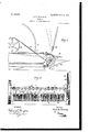
- Figure 1 is a sectional elevation of a sickle mechanism embodying my invention.
- Fig. 2 is a front view thereof.
- Fig. 3 shows the sickle-blade in plan.
- Fig. 4 is a detail illus trating the manner of directing the grain to the blade.
- Fig. 5 is a section on the line as a: of Fig. 1, and
- Fig. 6 shows the sickle-blade as coiled.
- 1 designates the draper of the machine, mounted on wheels 2 3.
- a cross-bar 4 Arranged at the front end of the upper portion of the draper is a cross-bar 4, to which the sickleblade 5 is attached.
- This sickle.- blade as before mentioned, is of very thin steel, so that it may be readily sharpened by an emery-wheel while on the machine, and upon removing the blade it will readily coil, similar to a watch-spring, so that it may be packed in a comparatively small space for transportation or storage.
- I provide screwbolts 6 at its ends, which pass through lugs 7 on the upper ends of standards 8, and these bolts are engaged by tension-nuts 9.
- pressers each comprising oppositelyextended and oppositely curved arms 16, which when in rotary motion pass underneath the space between the upper guide-fingers and force the grain against the blade 5.
- the ends of the arms 16 are somewhat widened and are concaved, as indicated at 17, these concaved portionsserving to engage the grain and force the same with a shearing or sliding action against the blade 5.
- the lower guides 12 alternate withthe guides 10, and the presser-arms that may be moving below the axis of the shaft will pass their ends through the channels 14, and thus the pressers will be prevented from striking the grain until they move to an uppermost position toward the sickle-blade.
- guard-plates 18 Extended upward from the lower bar 11 between the several pressers are guard-plates 18, the said guard-plates at their upper ends embracing the front side of the shaft 15 to form shields preventing the grain from engaging with and winding upon the shaft.
- M0- tion may be imparted to the shaft 15 through any desired connection with one of the machine-frames.
- a sprocketpinion 19 on the shaft from which a chain 20 extends to a connection with a sprocketwheel 21, mounted on the wheel 2.
- a portion of a reel 22 which serves to force straws or grain inward between the guidefingers until the grain is engaged by the concave ends of the pressers, which force the grain against the plate with a shearing motion, as before mentioned.
- a sickle-machine a wheel-mounted draper, spaced guides extending downward and forward at an incline at the forward end of the draper, a sickle-blade arranged at the forward end of the draper, the said guides be ing tapered at the sides, lower guides alternating with the first-named guides, a shaft, and pressers mounted on said shaft and operating between the upper and lower guides.
- a wheel-rnounted draper a bar extended across the forward end thereof, a sickleblade mounted on the bar, guides extended at a forward and downward incline from said bar, the said guides being tapered at the sides, a bottom cross bar, guides extended forward from said bottom cross bar and alternating With the firstnamed guides, the said lower guides being curved and channeled at their inner ends, a shaft, pressers consisting of oppositelyextendedarms mounted on said shaft and having broadened ends and adapted to pass through said channels of the lower guides,
- the said broadened ends being concaved, and means operated by a forward movement of the machine for rotating the shaft.
- a sickle-machine a wheel-mounted draper, a thin blade arranged at the forward end of the draper, guide-fingers extended forward from said blade and tapered at the opposite sides, lower guide fingers, a shaft, pressers mounted on said shaft, each consisting of oppositely-extended curved arms havneled, and rotary presser-arms movablethrough said channels.
Landscapes
- Life Sciences & Earth Sciences (AREA)
- Environmental Sciences (AREA)
- Crushing And Pulverization Processes (AREA)
Description
No. 809,676. PATENTED'.JAN. 9, 1906. P. E. FLETCHER.
SIGKLE.
APPLICATION FILED name, 1905.
2 SHEETS-SHEET I.
wnwssss; INVE/JTOR P Z EFL ic/z awn-4% if 6 er No. 809,676 PATENTED JAN. 9, 1906. P. E. FLETCHER.
SIGKLE.v
APPLICATION FILED APB.26,1905.
2 SHEETS-SHEET 2.
WITNESSES: INI/ENTOR FATE T OFFICE.
PEARL E. FLETCHER, OF RIDGE, OREGON, ASSIGNOR OF ONE-HALF TO KENNETH GEORGE WARNER, OF PENDLETON, OREGON.
SICKLE.
Specification of Letters Patent.
Patented Jan. 9, 1906.
Application filed April 26, 1905. Serial No, 257,491.
[ (DZ/Z 1071,0711, it may concern:
Be it known that I, PEARL E. FLETCHER, a citizen of the United States, and a resident of Ridge, in the county of Umatilla and State of Oregon, have invented a new and Improved Sickle, of which the following is a full, clear, and exact description.
This invention relates to improvements in sickle mechanism designed to be used in connection with a harvester, reaper, or binder, the object being to provide a sickle mechanism that will be of comparatively light draft, thus requiring but little power to run it, and, further, to employ a very thin sickle-blade that maybe readily sharpened with an emerywheel without removing the blade from the machine.
Other objects of the invention will appear in the general description.
Reference is to be had to the accompanying drawings, forming a part of this specification, in which similar characters of reference indicate corresponding parts in all the figures.
Figure 1 is a sectional elevation of a sickle mechanism embodying my invention. Fig. 2 is a front view thereof. Fig. 3 shows the sickle-blade in plan. Fig. 4 is a detail illus trating the manner of directing the grain to the blade. Fig. 5 is a section on the line as a: of Fig. 1, and Fig. 6 shows the sickle-blade as coiled.
Referring to the drawings, 1 designates the draper of the machine, mounted on wheels 2 3. Arranged at the front end of the upper portion of the draper is a cross-bar 4, to which the sickleblade 5 is attached. This sickle.- blade, as before mentioned, is of very thin steel, so that it may be readily sharpened by an emery-wheel while on the machine, and upon removing the blade it will readily coil, similar to a watch-spring, so that it may be packed in a comparatively small space for transportation or storage. To keep the blade under proper tension, I provide screwbolts 6 at its ends, which pass through lugs 7 on the upper ends of standards 8, and these bolts are engaged by tension-nuts 9.
Extended forward from the bar 4 and at a downward angle are the upper guide-fingers 10. These guide-fingers are beveled at their outer sides, so as to project to a point. Ex-
tended forward from a lower cross-bar 11 are the lower guides 12, the under sides of which are curved upward and forward, and their 1nner end portions are curved upward, as indicated at 13, these curved portions 13 being channeled, as indicated at 14,- the object of which will hereinafter appear.
Mounted rigidly on a cross shaft 15 are pressers, each comprising oppositelyextended and oppositely curved arms 16, which when in rotary motion pass underneath the space between the upper guide-fingers and force the grain against the blade 5. The ends of the arms 16 are somewhat widened and are concaved, as indicated at 17, these concaved portionsserving to engage the grain and force the same with a shearing or sliding action against the blade 5. It will be noted that the lower guides 12 alternate withthe guides 10, and the presser-arms that may be moving below the axis of the shaft will pass their ends through the channels 14, and thus the pressers will be prevented from striking the grain until they move to an uppermost position toward the sickle-blade.
Extended upward from the lower bar 11 between the several pressers are guard-plates 18, the said guard-plates at their upper ends embracing the front side of the shaft 15 to form shields preventing the grain from engaging with and winding upon the shaft. M0- tion may be imparted to the shaft 15 through any desired connection with one of the machine-frames. I have here shown a sprocketpinion 19 on the shaft, from which a chain 20 extends to a connection with a sprocketwheel 21, mounted on the wheel 2.
In Fig. 1 above the machine is indicated a portion of a reel 22 which serves to force straws or grain inward between the guidefingers until the grain is engaged by the concave ends of the pressers, which force the grain against the plate with a shearing motion, as before mentioned.
It will be noted that the several pressers are staggered on the shaft, so that practically no two operate together, and this will have a tendency to reduce the power required to operate the machine. 7
Having thus described my invention, I claim as new and desire to secure by Letters Patent 1. In a sickle-machine, a wheel-mounted draper, spaced guides extending downward and forward at an incline at the forward end of the draper, a sickle-blade arranged at the forward end of the draper, the said guides be ing tapered at the sides, lower guides alternating with the first-named guides, a shaft, and pressers mounted on said shaft and operating between the upper and lower guides.
2. In a sickle mechanism, awheel-rnounted draper, a bar extended across the forward end thereof, a sickleblade mounted on the bar, guides extended at a forward and downward incline from said bar, the said guides being tapered at the sides, a bottom cross bar, guides extended forward from said bottom cross bar and alternating With the firstnamed guides, the said lower guides being curved and channeled at their inner ends, a shaft, pressers consisting of oppositelyextendedarms mounted on said shaft and having broadened ends and adapted to pass through said channels of the lower guides,
the said broadened ends being concaved, and means operated by a forward movement of the machine for rotating the shaft.
3. In a sickle-machine, a wheel-mounted draper, a thin blade arranged at the forward end of the draper, guide-fingers extended forward from said blade and tapered at the opposite sides, lower guide fingers, a shaft, pressers mounted on said shaft, each consisting of oppositely-extended curved arms havneled, and rotary presser-arms movablethrough said channels.
6. In a sickle-machine, the combination with a blade and guide-fingers, of a rotary shaft, and oppositely-curved presser-arms arranged on said shaft, the ends of said arms being concavedQ In testimony whereof I have signed my name to this specification in the presence of two subscribing witnesses.
PEARL E. FLETCHER.
Witnesses:
S. A. LowELL, MABEL WHITMAN.
Priority Applications (1)
| Application Number | Priority Date | Filing Date | Title |
|---|---|---|---|
| US25749105A US809676A (en) | 1905-04-26 | 1905-04-26 | Sickle. |
Applications Claiming Priority (1)
| Application Number | Priority Date | Filing Date | Title |
|---|---|---|---|
| US25749105A US809676A (en) | 1905-04-26 | 1905-04-26 | Sickle. |
Publications (1)
| Publication Number | Publication Date |
|---|---|
| US809676A true US809676A (en) | 1906-01-09 |
Family
ID=2878157
Family Applications (1)
| Application Number | Title | Priority Date | Filing Date |
|---|---|---|---|
| US25749105A Expired - Lifetime US809676A (en) | 1905-04-26 | 1905-04-26 | Sickle. |
Country Status (1)
| Country | Link |
|---|---|
| US (1) | US809676A (en) |
-
1905
- 1905-04-26 US US25749105A patent/US809676A/en not_active Expired - Lifetime
Similar Documents
| Publication | Publication Date | Title |
|---|---|---|
| US809676A (en) | Sickle. | |
| US591606A (en) | Endless-chain cutter | |
| US374397A (en) | Cutter mechanism for reapers | |
| US762104A (en) | Sickle and cutter-bar for harvesters. | |
| US1053289A (en) | Cutting mechanism for harvesting-machines. | |
| US619192A (en) | Lawn-mower | |
| US1135463A (en) | Attachment for mowers. | |
| US178034A (en) | Improvement in mowers | |
| US83937A (en) | Improvement in horse-rakes | |
| US255510A (en) | Raking mechanism for harvesters | |
| US512720A (en) | Wire-reel | |
| US974358A (en) | Attachment for harvesters. | |
| US211522A (en) | Improvement in cotton-harvesters | |
| US10258A (en) | Improvement in the cutters of grain and grass harvesters | |
| US311364A (en) | Combined belt guide and reel for thrashing-machines | |
| US930168A (en) | Mowing-machine. | |
| US396816A (en) | Machine | |
| US97945A (en) | Improved mechanism for driving cotton-gins | |
| US588313A (en) | beall | |
| US10459A (en) | Improvement in grain-harvesters | |
| US1126091A (en) | Button-feeding mechanism. | |
| US973421A (en) | Mower attachment. | |
| US773491A (en) | Machine for making ornamental fence. | |
| US57082A (en) | Improvement in harvesters | |
| US1116294A (en) | Self-feeder for threshing-machines. |