US809671A - Shot-making machine. - Google Patents
Shot-making machine. Download PDFInfo
- Publication number
- US809671A US809671A US26693605A US1905266936A US809671A US 809671 A US809671 A US 809671A US 26693605 A US26693605 A US 26693605A US 1905266936 A US1905266936 A US 1905266936A US 809671 A US809671 A US 809671A
- Authority
- US
- United States
- Prior art keywords
- vessel
- metal
- shot
- aperture
- molten metal
- Prior art date
- Legal status (The legal status is an assumption and is not a legal conclusion. Google has not performed a legal analysis and makes no representation as to the accuracy of the status listed.)
- Expired - Lifetime
Links
- 229910052751 metal Inorganic materials 0.000 description 33
- 239000002184 metal Substances 0.000 description 33
- 239000002245 particle Substances 0.000 description 20
- 230000002093 peripheral effect Effects 0.000 description 12
- 239000007787 solid Substances 0.000 description 9
- 239000000463 material Substances 0.000 description 2
- 230000004048 modification Effects 0.000 description 2
- 238000012986 modification Methods 0.000 description 2
- 239000008188 pellet Substances 0.000 description 2
- 238000009825 accumulation Methods 0.000 description 1
- 239000011449 brick Substances 0.000 description 1
- 238000002485 combustion reaction Methods 0.000 description 1
- 239000004020 conductor Substances 0.000 description 1
- 238000010276 construction Methods 0.000 description 1
- 230000008602 contraction Effects 0.000 description 1
- 238000010438 heat treatment Methods 0.000 description 1
- 229910001385 heavy metal Inorganic materials 0.000 description 1
- 238000007689 inspection Methods 0.000 description 1
- 230000000717 retained effect Effects 0.000 description 1
Images
Classifications
-
- B—PERFORMING OPERATIONS; TRANSPORTING
- B22—CASTING; POWDER METALLURGY
- B22F—WORKING METALLIC POWDER; MANUFACTURE OF ARTICLES FROM METALLIC POWDER; MAKING METALLIC POWDER; APPARATUS OR DEVICES SPECIALLY ADAPTED FOR METALLIC POWDER
- B22F9/00—Making metallic powder or suspensions thereof
- B22F9/02—Making metallic powder or suspensions thereof using physical processes
- B22F9/06—Making metallic powder or suspensions thereof using physical processes starting from liquid material
- B22F9/08—Making metallic powder or suspensions thereof using physical processes starting from liquid material by casting, e.g. through sieves or in water, by atomising or spraying
- B22F9/10—Making metallic powder or suspensions thereof using physical processes starting from liquid material by casting, e.g. through sieves or in water, by atomising or spraying using centrifugal force
Definitions
- My invention relates to a machine for reducing molten metal into small solid particles, as shot, and provides a simple device capable of continuous operation. It also provides means for separating the dross from the metal and for adjustlng the machine to produce shot or particles of any desired size.
- Figure 1 represents in vertical section a shot-machine embodying my invention.
- Fig. 2 is an enlarged View of the vessel for holding the molten metal.
- Fig. 3 is a similar view showing a modified form of vessel.
- Fig. 4 is a view through the line 4 4, Fig.2.
- Fig. 5 shows a modified form of Fig. 6 is a vertical section of a modification of my device taken through the line 6 6, Fig. 7.
- Fig. 7 is a vertical section taken through the line 7 7, Fig. 6.
- l designates a vertical rotary shaft having a step-bearing 11 and shown as actuated by a motor 12.
- a metal vessel 2 for receiving the molten metal.
- the vessel 2 hasa flange 21 surrounding its upper edge, to which is bolted a cap 22, having a contracted central opening 23. Between the cap 22 and flange 21 washers 3 of any desired thickness may be inserted.
- a funnel 4 having its tube 41 extending into thecentral opening or mouth 23 of the vessel.
- a stationary jacket 5 of non-conducting material Surrounding the vessel 2 is a stationary jacket 5 of non-conducting material, as fire-brick or the like, provided with a bottom opening 51 for thepassage of the shaft 1 and with a pluality of lateral openings 52 for the passage of burner-tubes 61, inserted in an annular gas-pipe 6.
- the vessel 2 and connected parts are inclosed within a funnelshaped casing 7, which has a spout 71 leading into a receptacle 72.
- Fig. 5 of the drawings I have shown the vessel 2 as rotating on a horizontal axis.
- the form of construction is otherwise substantially like that shown in Figs. 1 and 2 of the drawings, except that necessarily the neck 42 of the funnel 4 is bent to enter the vessel 2. It is plain that by the contraction of the central opening or mouth 23 of the vessel 2 the only esca e for the molten metal 91 will be through t e peripheral apertures between the flan e 21 and cap 22.. It is obvious that any ot er form of peripheral aperture may be substitutede. g., the vessel shown in Fig. 3 might be turned into a horizontal position as well as that shown in Fig. 2.
- baffles '10 (indicated by dotted ines, Fig. 1) may be employed, against which the masses of metal will strike and flatten. It is obvious that these baffles or the continuous cylindric wall which they represent must be placed so near to the peripheral apertures of the vessel 2 as to assure the striking of the masses of metal a ainst the wall or bafiles 10 before it is entire y chilled. Where, e. g., the amount of dross or lighter impure material to be separated from;
- baflle such, for instance, as is shown in Figs. 6 and 7 of the drawings.
- This essentially is a plate of metal of a diameter slightly less than the interior diameter of the vessel and secured in any suitable manner near its upper end, so that the heavy metal 91 may flow out through the annular space between the periphery of the baflle and the wall of the vessel while the dross 92 is retained below the annular plate.
- the plate 8 is provided with a dished central portion 81, havingan aperture 82. It is also provided with three approximately vertical arms 83, having outturned portions 84 at their upper ends, pierced at 85 for the passa e of the bolts by which the cap 22 is secure to the flange 21 of the vessel 2. Inthis case the outturned portions 84 take the place of the washers 3 in separating the cap 22 the desired,distance from the u per edge of the vessel 2.
- an approxi-' mately cylindric rotatable vessel having a .peripheral emission-aperture so restricted in size as substantially to emit only small particles of metal, said aperture being located near the open end of said'vessel and at approximately its greatest diameter.
- an approximately cylindric vessel rotatable on a vertical axis and having a peripheral emission-aperture so restricted in size as substantially to emit only small particles of metal, said aperture being located near the open end of said vessel and at approximately its greatest diameter.
- an approximately cylindric rotatable vessel having its wall pierced by a plurality of emission-apertures so restricted in size as substantially to emit only small particles of metal, said apertures being located near the open end of said vessel and at approximately its greatest diameter.
- an approximately cylindric rotatable vessel having an open mouth and a peripheral emission-aperture so restricted in size as substantially to emit only small particles of metal, said aperture being located below said mouth, and.
- an approximately cylindric rotatable vessel having a peripheral emission-aperture so restricted in size as substantially to emit only small particles ofmetal, said aperture being located near the open end of said vessel and at approximatelyits greatest diameter, and means for maintaining the metal in said vessel in a molten condition.
- an approximately cylindric rotatable vessel having a peripheral emission-aperture so restricted in size as substantially to emit only small particles of metal, said aperture being located near the openend of said vessel and at aproximately its greatest diameter, a burner for heating the exterior of said vessel, and a non-conducting jacket surrounding said vessel and spaced away therefrom for holding the heated products of combustion in contact therewith.
- an approximately cylindric rotatable vessel having a peripheral emission-aperture so restricted in IIO metal into small solid particles
- a rotary vessel having a constricted emission-aperture near its open end, in combination with a baflle suitably supported in said vessel and spaced away fromthe inner wall of said vessel.
- a rotary vessel having a contracted mouth and constricted peripheral emission apertures, in combination with a baffle suitably supported in said vessel and providing an annular s ace between its periphery and the inner wa l of said vessel.
- a rotary vessel having a contracted mouth and constricted peripheral emission -apertur'es, in
Landscapes
- Furnace Charging Or Discharging (AREA)
Description
No'. 809,671.. PATENTED JAN. 9, 1906. P; P. GUWING.
SHOT MAKING MACHINE.
APPLICATION FILED JUNE 26.1905.
ETIIIII;
In ventor: :PEROY Fuors Covw'm the device. 5
UNITED STATES PATENT @FFIQE.
' Specification of Letters Patent.
Patented Jan. 9, 1906.
I Application filed June 26, 1905. Serial No. 266,936-
To all whom it may concern; 1
Be it known that I, PERCY FooTE CowINe, a citizen of-the United States, and a resident of the borough of Manhattan, city, county, and State ofNew York, have invented cer tain new and useful Improvements in Shot- Making Machines, of which the following is a specification.
My invention relates to a machine for reducing molten metal into small solid particles, as shot, and provides a simple device capable of continuous operation. It also provides means for separating the dross from the metal and for adjustlng the machine to produce shot or particles of any desired size.
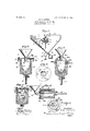
In the drawings, Figure 1 represents in vertical section a shot-machine embodying my invention. Fig. 2 is an enlarged View of the vessel for holding the molten metal. Fig. 3 is a similar view showing a modified form of vessel. Fig. 4 is a view through the line 4 4, Fig.2. Fig. 5 shows a modified form of Fig. 6 is a vertical section of a modification of my device taken through the line 6 6, Fig. 7. Fig. 7 is a vertical section taken through the line 7 7, Fig. 6.
Referring to Figs. 1, 2, and 4 of the drawings, l designates a vertical rotary shaft having a step-bearing 11 and shown as actuated by a motor 12. Mounted on the shaft 1 is a metal vessel 2 for receiving the molten metal. As shown, the vessel 2 hasa flange 21 surrounding its upper edge, to which is bolted a cap 22, having a contracted central opening 23. Between the cap 22 and flange 21 washers 3 of any desired thickness may be inserted. Above the vessel 2 is a funnel 4, having its tube 41 extending into thecentral opening or mouth 23 of the vessel. Surrounding the vessel 2 is a stationary jacket 5 of non-conducting material, as fire-brick or the like, provided with a bottom opening 51 for thepassage of the shaft 1 and with a pluality of lateral openings 52 for the passage of burner-tubes 61, inserted in an annular gas-pipe 6. As shown, the vessel 2 and connected parts are inclosed within a funnelshaped casing 7, which has a spout 71 leading into a receptacle 72..
The operation of the device will be readily understood from an inspection of the drawings It is clear that-the parts being assem- -.lo1ed, as shown, and the motor 12 or other source of power being employed to rotate the shaft 1 at the desired speed a supply of metal poured continuously or discontinuously through the funnel 4 into the vessel 1 and marked 91 will by centrifugal force be first separated from its dross (shown at 92, Fig. 2) and will be {ejected through the narrow annular slit between the flange 21 and the ca 22 substantially in the form of small partic es or in a stream so fine as to break up into. small particles as soon as it passes through the slit. These particles will be ra idly chilled in the air into shot or pellets tl e size of-which will be in part determined by the width of the annular opening. It is obvious that by connecting the annular gastube 6 with a supply of heating-gas the metal vessel 2 will be maintained at a suflicient heat to kee the lead or other molten metal therein in owing condition. As shown in Fig. '1, the shot or pellets ejected from' the slotted opening at the top of the vessel 2 are caught'in the casing 7 and delivered into the receptacle 72. y In Fi 3 of the drawings I have shown a modifie form of vessel 20, having an inturned fla e 201 surrounding a contracted mouth 202, in which the tube 41 of the funnel 4 enters. In this form of the device the upper portion of the side walls of the vessel20 1s pierced with a plurality of apertures 203, through which the metal is e ected. It is plain that in this case the size 0 the shot rouced may be determined by the s eedo rotation of the shaft 1 and the flui ity of the metal.
In Fig. 5 of the drawings I have shown the vessel 2 as rotating on a horizontal axis. The form of construction is otherwise substantially like that shown in Figs. 1 and 2 of the drawings, except that necessarily the neck 42 of the funnel 4 is bent to enter the vessel 2. It is plain that by the contraction of the central opening or mouth 23 of the vessel 2 the only esca e for the molten metal 91 will be through t e peripheral apertures between the flan e 21 and cap 22.. It is obvious that any ot er form of peripheral aperture may be substitutede. g., the vessel shown in Fig. 3 might be turned into a horizontal position as well as that shown in Fig. 2.
In each of the drawin s I have shown the vessel 2 as of cylindric orm. It is obvious that any approximation to this form, whether the vessel was somewhat larger or somewhat smaller at its open end, would be within the purview of the invention, it being only necessary that the vessel have a considerable depth as distinguished from a mere plate or saucer shaped vessel, so that space is provided for the accumulation of the dross. By the term approximately cylindric, therefore, as used in the claims I intend to include any form of vessel by which this function is obtained. 1
It is evident that various modifications other than those shown may be made without departing from the spirit of my invention.
Where it is desired to divide the molten metal into small masses of other than lobular form baffles '10 (indicated by dotted ines, Fig. 1) may be employed, against which the masses of metal will strike and flatten. It is obvious that these baffles or the continuous cylindric wall which they represent must be placed so near to the peripheral apertures of the vessel 2 as to assure the striking of the masses of metal a ainst the wall or bafiles 10 before it is entire y chilled. Where, e. g., the amount of dross or lighter impure material to be separated from;
the metal 1s considerable I provide a baflle. such, for instance, as is shown in Figs. 6 and 7 of the drawings. This essentially is a plate of metal of a diameter slightly less than the interior diameter of the vessel and secured in any suitable manner near its upper end, so that the heavy metal 91 may flow out through the annular space between the periphery of the baflle and the wall of the vessel while the dross 92 is retained below the annular plate.
In the example shown the plate 8 is provided with a dished central portion 81, havingan aperture 82. It is also provided with three approximately vertical arms 83, having outturned portions 84 at their upper ends, pierced at 85 for the passa e of the bolts by which the cap 22 is secure to the flange 21 of the vessel 2. Inthis case the outturned portions 84 take the place of the washers 3 in separating the cap 22 the desired,distance from the u per edge of the vessel 2.
By the p ase so restricted in size as substantially to emit only small particles of metal, as used in theclaims to qualify the emission-aperture, I of course intend to include an aperture of such size as to emit so fine a stream of molten metal as to break into small particles immediately on leaving the aperture.
. Without specifying materials or enumerating equivalents, what I claim is- 1. In a machine for converting molten metal into small solid particles, an approxi-' mately cylindric rotatable vessel having a .peripheral emission-aperture so restricted in size as substantially to emit only small particles of metal, said aperture being located near the open end of said'vessel and at approximately its greatest diameter.
2. In a machine for converting molten metal into small solid particles, an approximately cylindric vessel rotatable on a vertical axis and having a peripheral emission-aperture so restricted in size as substantially to emit only small particles of metal, said aperture being located near the open end of said vessel and at approximately its greatest diameter.
3. In a machine for converting molten metal into small solid particles, an approximately cylindric rotatable vessel having its wall pierced by a plurality of emission-apertures so restricted in size as substantially to emit only small particles of metal, said apertures being located near the open end of said vessel and at approximately its greatest diameter.
4. In a machine for converting molten metal into small solid particles, an approximately cylindric rotatable vessel having an open mouth and a peripheral emission-aperture so restricted in size as substantially to emit only small particles of metal, said aperture being located below said mouth, and.
means for feeding a supply of metal into said mouth.
5. In a machine for converting molten metal into small solid particles, an approximately cylindric rotatable vessel having a peripheral emission-aperture so restricted in size as substantially to emit only small particles ofmetal, said aperture being located near the open end of said vessel and at approximatelyits greatest diameter, and means for maintaining the metal in said vessel in a molten condition. a
6. In a machine for converting molten metal into small solid particles, an approximately cylindric rotatable vessel having a peripheral emission-aperture so restricted in size as substantially to emit only small particles of metal, said aperture being located near the openend of said vessel and at aproximately its greatest diameter, a burner for heating the exterior of said vessel, and a non-conducting jacket surrounding said vessel and spaced away therefrom for holding the heated products of combustion in contact therewith.
7. In a machine for converting molten metal into small solid particles, an approximately cylindric rotatable vessel having a peripheral emission-aperture so restricted in IIO metal into small solid particles, a rotary vessel having a constricted emission-aperture near its open end, in combination with a baflle suitably supported in said vessel and spaced away fromthe inner wall of said vessel.
9. In a shot-making machine, a rotary vessel having a contracted mouth and constricted peripheral emission apertures, in combination with a baffle suitably supported in said vessel and providing an annular s ace between its periphery and the inner wa l of said vessel.
10. In a shot-making machine, a rotary vessel having a contracted mouth and constricted peripheral emission -apertur'es, in
combination with an annular baflie having a central opening and a peripheral diameter slightly less than the interior diameter of the vessel, and means for supporting .said baflle Within said vessel 11; In a shot-making machine, a rotary vessel, a cap secured on said vessel and hav ing a contracted mouth and a baflle having In testimony whereof I have signed specification in the presence of two subscrib- 30 mg witnesses.
PERCY FOOTE OOWING Witnesses GEo. L. COOPER, L. BLANKMAN.
Priority Applications (1)
| Application Number | Priority Date | Filing Date | Title |
|---|---|---|---|
| US26693605A US809671A (en) | 1905-06-26 | 1905-06-26 | Shot-making machine. |
Applications Claiming Priority (1)
| Application Number | Priority Date | Filing Date | Title |
|---|---|---|---|
| US26693605A US809671A (en) | 1905-06-26 | 1905-06-26 | Shot-making machine. |
Publications (1)
| Publication Number | Publication Date |
|---|---|
| US809671A true US809671A (en) | 1906-01-09 |
Family
ID=2878152
Family Applications (1)
| Application Number | Title | Priority Date | Filing Date |
|---|---|---|---|
| US26693605A Expired - Lifetime US809671A (en) | 1905-06-26 | 1905-06-26 | Shot-making machine. |
Country Status (1)
| Country | Link |
|---|---|
| US (1) | US809671A (en) |
Cited By (4)
| Publication number | Priority date | Publication date | Assignee | Title |
|---|---|---|---|---|
| US2904859A (en) * | 1956-02-16 | 1959-09-22 | Marvalaud Inc | Method and apparatus for producing metal filaments |
| US3358323A (en) * | 1963-03-25 | 1967-12-19 | Dow Chemical Co | Processing of plastic |
| US3487502A (en) * | 1966-08-31 | 1970-01-06 | Schloemann Ag | Production of metal granules |
| US3741703A (en) * | 1971-04-26 | 1973-06-26 | Lilly Industries Ltd | An apparatus for making spherical granules |
-
1905
- 1905-06-26 US US26693605A patent/US809671A/en not_active Expired - Lifetime
Cited By (4)
| Publication number | Priority date | Publication date | Assignee | Title |
|---|---|---|---|---|
| US2904859A (en) * | 1956-02-16 | 1959-09-22 | Marvalaud Inc | Method and apparatus for producing metal filaments |
| US3358323A (en) * | 1963-03-25 | 1967-12-19 | Dow Chemical Co | Processing of plastic |
| US3487502A (en) * | 1966-08-31 | 1970-01-06 | Schloemann Ag | Production of metal granules |
| US3741703A (en) * | 1971-04-26 | 1973-06-26 | Lilly Industries Ltd | An apparatus for making spherical granules |
Similar Documents
| Publication | Publication Date | Title |
|---|---|---|
| US1267110A (en) | Apparatus for treating nuts. | |
| US809671A (en) | Shot-making machine. | |
| US1352623A (en) | Centrifugal machine and process of disintegrating material | |
| US845415A (en) | Cap-feeding machine. | |
| US617523A (en) | Breaking and feeding apparatus | |
| USRE12568E (en) | Reissued nov | |
| US1901203A (en) | Coal feeder | |
| US1728976A (en) | Apparatus for pulverizing coal | |
| US1893857A (en) | Pulverized fuel feeder | |
| US448844A (en) | Disintegrating and separating apparatus | |
| US569677A (en) | Centrifugal drying and filtering machine | |
| US4029302A (en) | Device for separation of mixtures of at least partially molten metals and/or metallic compounds into at least two phases of different density | |
| US1539606A (en) | Carbide-feeding means | |
| US556129A (en) | Louis evarist barbeau | |
| US1580620A (en) | Pulverizer | |
| US783251A (en) | Acetylene-gas generator. | |
| US665263A (en) | Centrifugal machine. | |
| US820568A (en) | Ore-separator. | |
| US800222A (en) | Furnace. | |
| US844373A (en) | Apparatus for treating tin cans and the like. | |
| US399113A (en) | Assigxors | |
| US2172718A (en) | Goijj separator | |
| US392454A (en) | Apparatus for treating molten slag or material from | |
| US1006143A (en) | Crushing-machine. | |
| US999698A (en) | Gas-producer. |