US809661A - Feeding mechanism for sewing-machines. - Google Patents
Feeding mechanism for sewing-machines. Download PDFInfo
- Publication number
- US809661A US809661A US20629004A US1904206290A US809661A US 809661 A US809661 A US 809661A US 20629004 A US20629004 A US 20629004A US 1904206290 A US1904206290 A US 1904206290A US 809661 A US809661 A US 809661A
- Authority
- US
- United States
- Prior art keywords
- shaft
- feed device
- feed
- sewing
- lever
- Prior art date
- Legal status (The legal status is an assumption and is not a legal conclusion. Google has not performed a legal analysis and makes no representation as to the accuracy of the status listed.)
- Expired - Lifetime
Links
- 230000007246 mechanism Effects 0.000 title description 10
- 238000010276 construction Methods 0.000 description 4
- 235000016499 Oxalis corniculata Nutrition 0.000 description 1
- 240000007019 Oxalis corniculata Species 0.000 description 1
- 230000008520 organization Effects 0.000 description 1
- 239000011435 rock Substances 0.000 description 1
- 238000009958 sewing Methods 0.000 description 1
Images

Classifications
-
- D—TEXTILES; PAPER
- D05—SEWING; EMBROIDERING; TUFTING
- D05B—SEWING
- D05B27/00—Work-feeding means
- D05B27/02—Work-feeding means with feed dogs having horizontal and vertical movements
Definitions
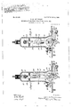
- Figure 1 is a rear e evation of a sewing-machine embodying my invention with certain parts thereof broken away and in section.
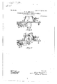
- Fig. 2 is a vertical section through line 2 2 of Fig. ,1 looking in the direction indicated by the arrows.
- Fi 3 is a similar view showing the position the parts at a different time durmg the operation of the machine.
- Figs. 4
- FIG. 1 and 5 are transverse sections through lines 4 4 and 5 5, respectively, of Fig. 1 looking in the direction indicated b the arrows.
- the frame of the machine illustrated in the drawings is of usual construction. Adjacent to the front end of the said bed-plate 1 and in usual position is the feed device proper, (indicated at 15.)
- This feed device 1s actuated to receive its" forward and backward or horizontal movement from a rock-shaft 16, which is mounted on conebearings 17 17 at the under side of the bedplate and rovided with two crank-arms 18 18 at or amfjacent to its opposite ends, one of which arms is pivotally connected with the rear end of the said feed device, as most clearly shown in Fig. 4, and the other of Specification of Letters Patent. Application filed May 4, 1904.
- a vertically-arranged link21 connects at its lower end with the said toggle-links at their connecting or toggle joint 22 and at its 0 posite or upper end connects with one end 0 a bellcrank lever 23, which is mounted upon a fulcrum-support 36, attached to the bracketarm 2, the said bell-crank lever 23 being con-.
- a reciprocatory actuating device herein shown as a pitman-lever 29, forming part of the shuttle-actuating mechanism, the said pitman-lever being connect ed at its upper end with a crank 28 in the up per driving-shaft 3 and sliding-through an opening in the said fulcrum-su port 36, as more fully described in my en ing application, Serial No. 198,184, file March 15, 1904.
- the fulcrum-pin 20 with which one of the toggle-links connects, is carried by a lever 26, termed the stitch regulator, which is pivoted at one end upon a stationary pivot 27,:attached to the bed-plate, and at its 0 posite end rojects throughaslot in the brac et-arm and is provided with a clamp ing-nut 26, which coacts with an arc-plate 30 on the-bed-plate to'secure the stitch-regulator in any desired position.
- the stitch regulator which is pivoted at one end upon a stationary pivot 27,:attached to the bed-plate, and at its 0 posite end rojects throughaslot in the brac et-arm and is provided with a clamp ing-nut 26, which coacts with an arc-plate 30 on the-bed-plate to'secure the stitch-regulator in any desired position.
- a tubular rock-shaft 32 is mounte on the'horizontal shaft 16 and is provided with two crank-arms 33 and 34, located adjacent to its opposite ends, the arm 33 at the front end of the shaft havinga pivotally-mounted ⁇ block 35 therein, engaging with the feed device within a slot 15 therein, as most clearly shown in Fig. 4, and the arm 34 at the rear end of said shaft having connection with the lower end of a pitman 37, which connects 'at its upper end with an actuating cam or eccentric 38 in a short rotating shaft 39, as most clearly shown in Fig.
- the said shaft 39 being actuated by the pitman-lever 29 through the medium of a crank-' arm 40 on said shaft, with which the lower end of the pitman-lever is pivotally connected.
- Vertical reciprocation of the pitman 37 as caused by the eccentric 38 imparts a rocking movement to the shaft 32, and thereby an up-and-down movement to the end of its arm 33, which is imparted to the connected feed device.
- a feed device means for imparting a horizontal movement to said feed device comprising a reciprocatory actuating device, a rock-shaft having two arms one of which is connected with the feed device, a toggle having connection with the second rock-shaft arm, and means including a pivoted lever and a plurality of links operatively connecting the said actuating device and the said toggle, and means for imparting avertical movement to the feed device.
- a feed device means for imparting a horizontal movement to said feed device comprising a reciproca- 'tory actuating device, a rock-shaft having two arms one of which is connected with the feed device, a toggle having connection with the second rock-shaft arm, and a pivoted lever having its opposite ends operatively connected through the medium of links with the said actuating device and the said toggle respectively, and means for imparting a vertical movement to the feed device.
- a feed device means for imparting a horizontal movement to said feed device comprising a drivingshaft, a pitmanlever operated from said shaft, a rock-shaft having two arms, one of which is connected with the feed device, a toggle having connection with the second rock-shaft arm, and a pivoted lever having connection with the pitman-lever through the medium of a link and also having connection with said to gle through the medium of a second link, and means for imparting a vertical movement to the feed device.
- a feed device means for imparting a horizontal movement to said feed device comprising a drivingshaft, a pitman operated from said shaft and forming part of the shuttle-actuating mechanism, a rock-shaft having two arms one of which is connected with the feed device, a toggle having connection at one end with the second arm of the rock-shaft and at its opposite end having connection with an adjustable support, and a pivoted lever having one arm thereof connected with the said pitman through the medium of a link and its other arm connected with the said toggle through the medium of a second link, and means for imparting a vertical movement to the feed device.
- a feed device means for imparting a horizontal movement to said feed device comprising'a rock-shaft havin two arms one of which is connected with the feed device, a toggle having connection with the second rock-shaft arm, a pivoted lever having connection with said togg Signed at New York, in the county of New through the medium of a link, and means actuating said lever and moving the same April, A. D. 1904:.
Landscapes
- Engineering & Computer Science (AREA)
- Textile Engineering (AREA)
- Sewing Machines And Sewing (AREA)
Description
PATENTED JAN. 9, 1906.
W. M. AMMERMAN.
FEEDING MECHANISM FOR SEWING MACHINES.
APPLICATION FILED MAY4, 1904.
3 SHEETS-SHEET 1.
an r 7 v I-IIIII'IHI III! I WIN? I it PATENTED JAN. 9, 1906. W. M. AMMERMAN.
FEEDING MECHANISM FOR SEWING MACHINES.
APPLICATION FILED MAY/1.1904.
3 SHEETS-SHEET 2.
ammo/mica PATENTED JAN. 9, 1906.
W. M. AMMERMAN.
FEEDING MECHANISM FOR SEWING MACHINES. APPLICATION FILED MAY4, 1904.
8 SHEETS-SHEET 3.
Wmeooeo gmwtoz UNITED STATES PATENT OFFICE.
WILLIAM M. AMMERMAN, OF NEW HAVEN, CONNECTICUT, ASSIGNOR TO THE EDWIN J. TOOF COMPANY, OF NEW HAVEN, CONNECTICUT, A COR- PORATION OF NEW JERSEY.
FEEDING MECHANISM FOR SEWING-MACHINES.
To all whom it may concern:
Beit known that I, WILLIAM M. AMMER- machines that will cooperate with the severral other parts of the stitch-forming mechanism in such time as to perform its function Without causing undue strain or pull on the thread or any of the cooperating parts and that will also be so constructed and organized as to assure the greatest ease of operation, and thereby increase the light-running qualities of the machine of which it may form a part. This object I attain by means of the novel construction and combination of parts, as hereinafter set forth in detail, and pointed out in the claims.
Referring to the accompanying drawings, forming a art of this specification, Figure 1 is a rear e evation of a sewing-machine embodying my invention with certain parts thereof broken away and in section. Fig. 2 is a vertical section through line 2 2 of Fig. ,1 looking in the direction indicated by the arrows. Fi 3 is a similar view showing the position the parts at a different time durmg the operation of the machine. Figs. 4
and 5 are transverse sections through lines 4 4 and 5 5, respectively, of Fig. 1 looking in the direction indicated b the arrows.
Similar reference 0 aracters designate lik parts in all the figures of the drawings. 4
The frame of the machine illustrated in the drawings,.comprising the bed-plate 1 and its attached bracket-arm 2, is of usual construction. Adjacent to the front end of the said bed-plate 1 and in usual position is the feed device proper, (indicated at 15.) This feed device 1s actuated to receive its" forward and backward or horizontal movement from a rock-shaft 16, which is mounted on conebearings 17 17 at the under side of the bedplate and rovided with two crank-arms 18 18 at or amfjacent to its opposite ends, one of which arms is pivotally connected with the rear end of the said feed device, as most clearly shown in Fig. 4, and the other of Specification of Letters Patent. Application filed May 4, 1904. Serial No. 206,290.
Patented Jan. 9, 1906.
which iszconnected with one of a pair of toggle-links;19 19, the other of which latter is connected with a fulcrum-pin 20. A vertically-arranged link21 connects at its lower end with the said toggle-links at their connecting or toggle joint 22 and at its 0 posite or upper end connects with one end 0 a bellcrank lever 23, which is mounted upon a fulcrum-support 36, attached to the bracketarm 2, the said bell-crank lever 23 being con-. nected at its other end through the medium of a link 25 with a reciprocatory actuating device, herein shown as a pitman-lever 29, forming part of the shuttle-actuating mechanism, the said pitman-lever being connect ed at its upper end with a crank 28 in the up per driving-shaft 3 and sliding-through an opening in the said fulcrum-su port 36, as more fully described in my en ing application, Serial No. 198,184, file March 15, 1904. By the arrangement and combination of parts as described. movementof the pitman 29 communicates a rocking moven'ient to the lever 23 through the link 25, and, said lever in turn causes a vertical reciprocation of the link-21-Which raises and lowers the connecting to gle-links at their junction, and thereby roc ks the shaft 16 and 'causes'hori'z'ontal movement of the feed. To rovide for the adjustment of this horizonta l movement of the feed, the fulcrum-pin 20, with which one of the toggle-links connects, is carried by a lever 26, termed the stitch regulator, which is pivoted at one end upon a stationary pivot 27,:attached to the bed-plate, and at its 0 posite end rojects throughaslot in the brac et-arm and is provided with a clamp ing-nut 26, which coacts with an arc-plate 30 on the-bed-plate to'secure the stitch-regulator in any desired position. By raising or lowering the outer end of this stitch-regulator the position of the fulcrum-pin 20,carried thereby, is so changed as to cause the connected toggle-links at their junction to swing or move at a greater or less angle to a vertical line when 0 erated by the link 21 and so increase or iminish the longitudinal movement of that toggle-link which connects with the crank arm of the rock -shaft 16, and thereby vary the throw of the latter and the connected feed device accordingly.
By operating the feed-shaft 16 from the pitmanlever 29 of the shu .le actuating mechanism in the manner described instead of from a second crank or equivalent device chine'will be caused to run with greater ease and also with less noise and vibration. Moreover, by making a direct connection between the feed and shuttle mechanisms in the manner described the parts can be more readily and accurately assembled than if independent connections were effected between said mechanisms and the driving-shaft and also with less possibility of the parts subsequently getting out of adjustment.
The vertical or up-and-down movement of the feed is effected in the present case by the followin means: A tubular rock-shaft 32 is mounte on the'horizontal shaft 16 and is provided with two crank- arms 33 and 34, located adjacent to its opposite ends, the arm 33 at the front end of the shaft havinga pivotally-mounted {block 35 therein, engaging with the feed device within a slot 15 therein, as most clearly shown in Fig. 4, and the arm 34 at the rear end of said shaft having connection with the lower end of a pitman 37, which connects 'at its upper end with an actuating cam or eccentric 38 in a short rotating shaft 39, as most clearly shown in Fig. 5, the said shaft 39 being actuated by the pitman-lever 29 through the medium of a crank-' arm 40 on said shaft, with which the lower end of the pitman-lever is pivotally connected. Vertical reciprocation of the pitman 37 as caused by the eccentric 38 imparts a rocking movement to the shaft 32, and thereby an up-and-down movement to the end of its arm 33, which is imparted to the connected feed device.
The construction and or anization of the several parts constituting t e feeding mechanism as described assures the desired and proper cooperation of the same with the other parts of the stitch-forming mechanism, the action of the feed device being such that it does not be in its forward or working stroke until the s uttle has ceased draw1n the thread through the work and cast off the thread-loop to be drawn up by the take-up and then remains in operative engagement with the work only when the needle is raised above and disengaged therefrom.
The desired timing in the action of the feed whereby it will not engage the work until after the needle has raised from engagement therewith is secured by that construction and organization of the feed-actuating parts whereby the bell-crank lever 23 just prior to the raising of the feed into engagement with the work is moved to the position shown in Fig. 3, with the point of connection 21 between it and the link 21 at or adjacent to a dead-center, at which position of the parts the movement of the feed will be arrested sufliciently to permit the raising of the needle above the work and also a substantially straight upward movement of the feed into engagement with the work.
What I claim is 1. In a sewing-machine, a feed device, means for imparting a horizontal movement to said feed device comprising a reciprocatory actuating device, a rock-shaft having two arms one of which is connected with the feed device, a toggle having connection with the second rock-shaft arm, and means including a pivoted lever and a plurality of links operatively connecting the said actuating device and the said toggle, and means for imparting avertical movement to the feed device.
2. In a sewing-machine, a feed device, means for imparting a horizontal movement to said feed device comprising a reciproca- 'tory actuating device, a rock-shaft having two arms one of which is connected with the feed device, a toggle having connection with the second rock-shaft arm, and a pivoted lever having its opposite ends operatively connected through the medium of links with the said actuating device and the said toggle respectively, and means for imparting a vertical movement to the feed device.
3. In a sewing 4 machine, a feed device, means for imparting a horizontal movement to said feed device comprising a drivingshaft, a pitmanlever operated from said shaft, a rock-shaft having two arms, one of which is connected with the feed device, a toggle having connection with the second rock-shaft arm, and a pivoted lever having connection with the pitman-lever through the medium of a link and also having connection with said to gle through the medium of a second link, and means for imparting a vertical movement to the feed device.
4. In a sewingmachine, a feed device, means for imparting a horizontal movement to said feed device comprising a drivingshaft, a pitman operated from said shaft and forming part of the shuttle-actuating mechanism, a rock-shaft having two arms one of which is connected with the feed device, a toggle having connection at one end with the second arm of the rock-shaft and at its opposite end having connection with an adjustable support, and a pivoted lever having one arm thereof connected with the said pitman through the medium of a link and its other arm connected with the said toggle through the medium of a second link, and means for imparting a vertical movement to the feed device.
5. In a sewing-machine, a feed device, means for imparting a horizontal movement to said feed device comprising'a rock-shaft havin two arms one of which is connected with the feed device, a toggle having connection with the second rock-shaft arm, a pivoted lever having connection with said togg Signed at New York, in the county of New through the medium of a link, and means actuating said lever and moving the same April, A. D. 1904:.
and the connected link to and from a position WILLIAM M. AMMERMAN. 5 at or adjacent to a dead-center, and means Witnesses:
for imparting a vertical movement to the CHAS. F. DANE,
feed device. E. M. FAITH.
le or York and State of New York, this 8th day of
Priority Applications (1)
| Application Number | Priority Date | Filing Date | Title |
|---|---|---|---|
| US20629004A US809661A (en) | 1904-05-04 | 1904-05-04 | Feeding mechanism for sewing-machines. |
Applications Claiming Priority (1)
| Application Number | Priority Date | Filing Date | Title |
|---|---|---|---|
| US20629004A US809661A (en) | 1904-05-04 | 1904-05-04 | Feeding mechanism for sewing-machines. |
Publications (1)
| Publication Number | Publication Date |
|---|---|
| US809661A true US809661A (en) | 1906-01-09 |
Family
ID=2878142
Family Applications (1)
| Application Number | Title | Priority Date | Filing Date |
|---|---|---|---|
| US20629004A Expired - Lifetime US809661A (en) | 1904-05-04 | 1904-05-04 | Feeding mechanism for sewing-machines. |
Country Status (1)
| Country | Link |
|---|---|
| US (1) | US809661A (en) |
-
1904
- 1904-05-04 US US20629004A patent/US809661A/en not_active Expired - Lifetime
Similar Documents
| Publication | Publication Date | Title |
|---|---|---|
| US809661A (en) | Feeding mechanism for sewing-machines. | |
| US2024434A (en) | Feeding mechanism for sewing machines | |
| US804220A (en) | Sewing-machine feeding mechanism. | |
| US1006827A (en) | Automatic clamp feeder and releaser. | |
| US1147047A (en) | Differential feeding mechanism. | |
| US306996A (en) | Baebee | |
| US1506024A (en) | Straw-sewing machine | |
| US645833A (en) | Chain-stitch sewing-machine. | |
| US1407023A (en) | Differential feeding mechanism for sewing machines | |
| US207035A (en) | Improvement in blind-stitch sewing-machines | |
| US1178055A (en) | Feeding mechanism for sewing-machines. | |
| US1127069A (en) | Sewing-machine. | |
| US1319470A (en) | gatchell | |
| US1133572A (en) | Sewing-machine. | |
| US1368245A (en) | Feeding mechanism for sewing-machines | |
| US89040A (en) | Improvement in sewing-machines | |
| US705577A (en) | Feeding mechanism for sewing-machines. | |
| US1435454A (en) | Feeding mechanism for sewing machines | |
| US432957A (en) | Island | |
| US998770A (en) | Overseaming sewing-machine. | |
| US339624A (en) | Philip diehl | |
| US1334651A (en) | Looper mechanism for overseaming sewing-machines | |
| US884579A (en) | Sewing-machine. | |
| US724110A (en) | Overedge sewing-machine. | |
| US828962A (en) | Attachment for looping-machines. |