US809659A - Purifier for gas. - Google Patents
Purifier for gas. Download PDFInfo
- Publication number
- US809659A US809659A US26553205A US1905265532A US809659A US 809659 A US809659 A US 809659A US 26553205 A US26553205 A US 26553205A US 1905265532 A US1905265532 A US 1905265532A US 809659 A US809659 A US 809659A
- Authority
- US
- United States
- Prior art keywords
- box
- valve
- pipe
- filter
- gas
- Prior art date
- Legal status (The legal status is an assumption and is not a legal conclusion. Google has not performed a legal analysis and makes no representation as to the accuracy of the status listed.)
- Expired - Lifetime
Links
Images
Classifications
-
- F—MECHANICAL ENGINEERING; LIGHTING; HEATING; WEAPONS; BLASTING
- F02—COMBUSTION ENGINES; HOT-GAS OR COMBUSTION-PRODUCT ENGINE PLANTS
- F02M—SUPPLYING COMBUSTION ENGINES IN GENERAL WITH COMBUSTIBLE MIXTURES OR CONSTITUENTS THEREOF
- F02M1/00—Carburettors with means for facilitating engine's starting or its idling below operational temperatures
Definitions
- acetylene gas for illuminating purposes when it comes from the generator it usually contains more or less impurities, which for good results must be removed as much as possible before the gas is admitted to the burner-tube. It is common to conduct the gas through some sort of purifier or lilter for the purpose of removing these impurities. After the filter has been in use for some time it is necessaryT to clean it out and to renew the filtering substance.
- the object of my invention is to provide a new and useful filtering apparatus adapted to form the connection between the feed-pipe from the generator and the pipe which supplies the house. Then the apparatus is in operative position, it provides a passage for the gas lfrom the feed-pipe through the purifier and into the house-pipe. It is mounted so that it may be rotated, and when it is turned into an inverted position it closes the passage from the feed-pipe to the purifier and the passage from the purifier to the house-pipe and opens an outlet-port to a dripn pipe to carry oHthe filtering liquid. When it is in the inverted position, it maybe opened to permit access to the interior to further clean it, to change the filtering material, and for any other purpose desired. The cover of the filter-box then may be closed again and fastened down, the box reversed, and in so doing the valve opens the passages for the gas.
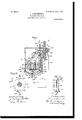
- Figure 1 is a sectional elevation of an apparatus embodying the invention with the box or tank in the operative position, the removable cover being on the under side.
- Fig. 2 is a vertical section on line 2 2 of Fig. 1.
- Fig. 3 is a vertical section of the filter-tube removed.
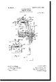
- Fig. 4 is a sectional elevation showing the box or tank rotated into an inverted position, bringing the clean-out opening and cover on the upper side.
- Fig. 5 is a sectional view, partly showing the strap which holds the cover turned back on its hinge, so that the cover may be removed.
- 1 represents a feed-pipe leading from a generator A to the interior of the valve-casing 2.
- the generator is only conventionally shown. It forms no part of the present invention.
- the pipe 3 leads from the interior of the valvecasing to supply the burner.
- valve 4 represents the filter box or tank, which is preferably cylindrical in form and contains the filtering liquid 5. Any of the wellknown Jiiltering materials on the market may be used. The special composition of the 'filtering material forms no part of this invention.
- the interior of the valve-casing is cylindrical, preferably somewhat tapering, to receive the rotary valve 6, which is rotatably mounted therein.
- One end of said valve 6 enters one side of the filter-box 4, near that end which is the upper end when in operative position and which becomes the lower end when the iilter-box is in its inverted position. .
- the valve is fast to the filter-box, so that when the valve is rotated the filter-box will also rotate with it. There are two passages from the valve into the filter-box.
- One passage 7 leads frorn the filter-box to an outletport 8, with which the house-supply pipe or burner-tube 3 is connected.
- the passage 81 leads from the filter-box through the valve to an inlet-port 9, with which the 'feed-pipe 1 is connected.
- the lower end of the filter-box is closed by a cap 10, which forms the bottom of the box when in operative position.
- the special method of fastening is not material, but the form shown will be later described.
- At a short distance above the cap 10 there is a diaphragm l1, extending crosswise of the box and forming a chamber 12 between the cap and the diaphragm.
- a pipe 13 leads from the inlet-passage S1 of the valve down through the diaphragm 11 into the chamber 12.
- a hole 14 Through the diaphragm 11 is a hole 14, provided with a flanged annular bushing 15, tapped out to receive a screw-threaded annular plug 16.
- the plug 1.6 is formed with a iange 17 and provided with a gasket or washer 18 to make a tight joint.
- Fitted into the interior of the annular plug 16 and fixed thereto is a tube 19, which extends up some distance into the 'filter-box.
- the plug 16 is provided with a -linger-piece 2O for turning it to screw it inand unscrew it.
- a thimble 23 is attached to the upper end of the tube 19 and surrounds the filtering fabric 22 and extends down far enough bey low the ports 21 to enter the filteringliquid 5. It is not necessary that it should extend down the full length of the filtering fabric.
- the preferred method of securing the thimble 23 to the tube 19 is to provide the upper end of the tube with a screw-threaded stem 24 and to tap out the head 25 of the thimble, so that it may be screwed onto the stern 24.
- the lower end of the thimble 23 is corrugated or notched, forming teeth 26 to intercept or break up the bubbles of gas as the gas passes down through the liquid and out of the lower end of the thimble.
- valve 1 the valve is open and the gas flows in the direction shown by the arrows from the generator through the feed-pipe 1, valve-inlet 9, valve-passage 8, tube 13, into chamber 12, thence up into and through the tube 19, through the ports 21 in the side of tube 19, through the felt tubing 22, down between the felt tubing and the thimble 23, into the filtering liquid 5, the bubbles of gas being broken up by the saw-teeth 26 as the gas passes out from the under side of the thimble, thence up through the liquid into the upper part of the filter-box above the liquid, thence into and through the valve-passage 7 to the house-pipe or burner-tube 3.
- the filter-box is closed tight except for the openings already described connecting with the inletpassage 81 and outlet-passage 7, so that the gas cannot escape.
- a cap 10 fits into the end of the cylinder.
- a strap 28 is hinged at one end at 29 to the edge of the box and is formed at the other end with a hook 44, with which a link 30, hinged at 31, is adapted to engage.
- a set-screw 32 passes through the strap 28 and engages with the cap 10, whereby the cap may be held tightly closed.
- the cap is preferably provided with a gasket 33 to form a tight joint. The screw 32 may be loosened to release the cap when desired to remove it.
- the box 4 When it is desired to'clean the filter, the box 4 is turned a half-revolution, bringing the box into an inverted position, as shown in Fig. 4, so that the end closed by the cap comes uppermost.
- the valve 6 is fast to the filter-box and forms the axle or journal for the filter-box, as already described, and consequently the valve turns with the box and closes the inlet-port 9 and outlet-port 8, so that no gas lcan enter from the feed-pipe 1 or pass into the house-pipe 3.
- An outlet-port 34 leads from the interior of the valve-casing through the side of the valve-casing to a drain-pipe 35, provided with a stop-cock 36.
- This outletport 34 is located on the opposite side of the valve-casing from the outlet-port 8 which connects with the house-pipe, and when the valve is rotated from the operative position shown in Fig. 1, in which the passage 7 connects with the port 8, the passage 7 will now connect with the drain-outlet 34. Vhen the filter-box is in this reversed position, the passage 7 will lead from what now becomes the lower part of the box, so that when the stopcock 36 is opened the liquid will drain 0H through passage 7 and drain-pipe 35.
- the valve-casing 2 is provided with an annular flange 37. Attached to the hinged end of the strap 28 is a hookfinger 38, which passes through an eye 39 in a slide-rod 40. Slide-rod 40 passes through guides 41 and is formed at its lower end with a fork 42. The fiange 37 is formed with a notch 43, which is on the upper side when the valve and box are in the position for cleaning. When the strap 28 is turned back on its hinge, the fork 42 will engage the notch 43 and prevent the box and valve from being rotated. When the strap 28 is unhooked and turned back on its hinge, the cap 10 can be removed.
- the screw-plug 16 can now be unscrewed and removed, thereby also removing with it the tube 19 and carrying with it the thimble 23 and felt tubing 22.
- the felt tubing can now be easily replaced by a fresh one, and access may be had to the interior of the filter-box, if desired, to further cleanse it and to pour in fresh filtering material.
- the cock 36 should be closed. Connecting with the drain-pipe 35 between the stop-cock 36 and the interior casing is a gage-pipe 45, which is open at the top and extends upward to the proper height for the filtering liquid in the box.
- the filtering liquid When the filtering liquid is poured into the box, it will rise also in the gage-pipe, and when it Hows over the top of the gage-pipe it indicates that the filter-box is sufficiently filled.
- the screw-plug 16 and tube 19 will now be put back in place, the cap 10 inserted, and the strap 28 turned back in the clamping position, and the set-screw 32 set up to tightly close the cap.
- the strap 28 is thus turned up, it will lift the slide-rod 40, releasing the fork 42 from the notch 43, although the fork 43 will still embrace the edge of the disk flange 37, but not interfere with the rotation of the flange and the valve.
- the inner end For convenience in turning the valve the inner end is provided with a crank-handle 46, which may be held on by clamp-nut 47.
- a purifier for gas comprising a filterbox, a rotary valve fast to said box and havincr an inlet passage leading through said v( ve into said box and an outlet-passage leading from said box out through said valve, a valve-casing having a cylindrical chamber in which said valve is journaled, an inlet-passage through the valve-casing with which a feed-pipe and the inlet-passage in the valve are adapted to connect, an outlet -passage through the valve-casing with which the outlet-passage in the valve and a burner-tube are adapted to connect, means for rotating said valve and filter-box to close said inlet and outlet passages, and a drain-passage through said valve-casing to the outside air with which said gas-outlet passage in the valve connects when the valve and box are reversed to close the gas-passages.
- a purifier for as comprising a reversible filter-box, a vadve-casing, a valve connected with said box and havin a passage leading from the feed-pipe throug the valvecasing and valve into said filter-box and a passage leading from said filter-box through the valve and casing into a house supply pipe, means for reversing said box and valve, thereby closing said valve inlets and outlets, and a drain-passage through the valve-casing with which one of the passages in the valve connects when the valve and filter -box are reversed.
- a purifier for gas having a rotatable filter-box, an opening in the bottom of the box, a cover for said opening, a valve connected with the upper part of said box and having a passage connectin T therethrough with an inlet-pipe, a passagecleading therethrough to an outlet-pipe, a diaphragm dividing the filter-box into two chambers, a pipe leading from said inlet-passage of the valve into the lower chamber, a pipe leading from said lower chamber and projectingv up some distance into the upper chamber, perforations in the upper portion of said second tube, a filtering material in said upper chamber below said perforations, a thimble over the upper end of said second pipe and extending down into said filtering material, means for turning said filter-box and valve to reverse the ends of the box, and close the gas inlets and outlets of the valve, and an outlet-passage for drawing off the filtering material from the box when the box is in the said reversed position.
- a purifier for gas having a filter-box, a valve connected with the upper part of said box and having a passage connecting therethrough with an inlet-pipe, a passage leading therethrough to an outlet-pipe, a diaphragm dividing the filter-box into two chambers, a pipe leading from said inlet-passage of the valve into the lower chamber, a pipe leading from said lower chamber and projecting up some distance into the upper chamber, perforations in the upper portion of said second tube, a filtering material in said upper chainber below said perforations, and a thimble over the upper end of said second pipe and extending down into said filtering material.
- a purifier for gas having a filter-box, a valve connected with the upper part of said box and having a passage connecting therethrough with an inlet-pipe, a passage leading therethrough to an outlet-pipe, a diaphragm dividing the filter-box into two chambers, a pipe leading from said inlet-passage of the valve into the lower chamber, a pipe leading from said lower chamber and projecting up some distance into the upper chamber, perforations in the upper portion of said second tube, a filtering material in said upper chamber below said perforations, and a thimble over the upper end of said second pipe and extending down into said filtering material, said thimble being formed with teeth on its lower end.
- a purifier for gas having a rotatable filter-box, an opening in the bottom of the box, a cover forsaid opening, a valve connected with the upper part of said box and having a passage connecting therethrough with an inlet-pipe, a passage leading therethrough to an outlet-pipe, a diaphragm dividing the filter-box into two chambers, a pipe leading from said inlet-passage of the valve into the lower chamber, a pipe leading from said lower chamber and projecting up some distance into the upper chamber, perforations in the upper portion of said second tube, a filtering material in said upper chamber below said perforations, a tube of fabric incasing the perforated portion of the pipe, and a thimble over the upper end of said pipe outside of said fabric tube and extending down into the filtering material.
- a purifying apparatus for gas having a box divided by a diaphragm into an upper and lower chamber, an inlet-pipe for the impure gas leading into the lower chamber, an upright tube leading from the interior of the lower chamber up seine distance into the upper chamber, perforations in the upper portion of the said tube, filtering material partially filling the upper chamber but not eX- lOO IIO
- a reversible filter-box for purifying gas having an opening in the lower end of the boX, a cover for said opening, means for clamping said cover in a closed position with gas-tight joint, a diaphragm dividing the boX into an upper and lower chamber, an inlettube for the impure gas leading into the lower chamber, a removable pipe having a screwthreaded connection with a socket in said diaphragm and extending up into the said upper chamber, an opening from the lower chamber into said pipe, ports in the upper portion of said pipe opening into the upper chamber, a filtering material in said upper chamber, but not reaching up to said ports, and a deflector on the upper end of said pipe extending down into said filtering material, means for inverting said boX and closing the inlet and outlet for the gas, and an outlet-passage which connects with the portion of the boX which becomes the lower end when the boX is in the inverted position.
- a rotary filter-box for purifying gas having an opening in the lower end of the boX, a cover for said opening, a hinged clamp
Landscapes
- Engineering & Computer Science (AREA)
- Chemical & Material Sciences (AREA)
- Combustion & Propulsion (AREA)
- Mechanical Engineering (AREA)
- General Engineering & Computer Science (AREA)
- Filtering Of Dispersed Particles In Gases (AREA)
Description
No. 809,659. PATENTBD JAN. 9, 1906.
B., o. wooDwoRTH.
PURIPIER PoR GAS.
APPLICATION FILED JUNE 16, 1905.
2 SHEETS-SHEET 1.
I lf l No. 809,659. PATBNTED JAN. 9, 1906. E. C. WOODWORTH; PURIFIER FOR GAS.
APPLICATION FILED JUNE 1s, 1905.
2 SHEETS-SHEET 2.
UNTTED STATES PATENT OFFICE.
Specification of Letters Patent.
Patented Jan. `9, 1906.
Application filed June 16, 1905. Serial No. 265,532.
To all roh/mn it may concern:
Be it known that I, ELMER @.WooDwoRrH, of Deer Isle, in the county of Hancock and State of Maine, have invented certain new and useful Improvements in Purifiers for Acetylene Gas, Vof which the following is a specification.
In the use of acetylene gas for illuminating purposes when it comes from the generator it usually contains more or less impurities, which for good results must be removed as much as possible before the gas is admitted to the burner-tube. It is common to conduct the gas through some sort of purifier or lilter for the purpose of removing these impurities. After the filter has been in use for some time it is necessaryT to clean it out and to renew the filtering substance.
The object of my invention is to provide a new and useful filtering apparatus adapted to form the connection between the feed-pipe from the generator and the pipe which supplies the house. Then the apparatus is in operative position, it provides a passage for the gas lfrom the feed-pipe through the purifier and into the house-pipe. It is mounted so that it may be rotated, and when it is turned into an inverted position it closes the passage from the feed-pipe to the purifier and the passage from the purifier to the house-pipe and opens an outlet-port to a dripn pipe to carry oHthe filtering liquid. When it is in the inverted position, it maybe opened to permit access to the interior to further clean it, to change the filtering material, and for any other purpose desired. The cover of the filter-box then may be closed again and fastened down, the box reversed, and in so doing the valve opens the passages for the gas.
The invention will now be fully decribed, reference being had to the accompanying drawings, and the novel features thereof will be particularly pointed out in the claims at the close of the specification.
In the drawings, Figure 1 is a sectional elevation of an apparatus embodying the invention with the box or tank in the operative position, the removable cover being on the under side. Fig. 2 is a vertical section on line 2 2 of Fig. 1. Fig. 3 is a vertical section of the filter-tube removed. Fig. 4 is a sectional elevation showing the box or tank rotated into an inverted position, bringing the clean-out opening and cover on the upper side. Fig. 5 is a sectional view, partly showing the strap which holds the cover turned back on its hinge, so that the cover may be removed.
Referring now to the drawings, 1 represents a feed-pipe leading from a generator A to the interior of the valve-casing 2. The generator is only conventionally shown. It forms no part of the present invention. The pipe 3 leads from the interior of the valvecasing to supply the burner.
4 represents the filter box or tank, which is preferably cylindrical in form and contains the filtering liquid 5. Any of the wellknown Jiiltering materials on the market may be used. The special composition of the 'filtering material forms no part of this invention. The interior of the valve-casing is cylindrical, preferably somewhat tapering, to receive the rotary valve 6, which is rotatably mounted therein. One end of said valve 6 enters one side of the filter-box 4, near that end which is the upper end when in operative position and which becomes the lower end when the iilter-box is in its inverted position. .The valve is fast to the filter-box, so that when the valve is rotated the filter-box will also rotate with it. There are two passages from the valve into the filter-box. One passage 7 leads frorn the filter-box to an outletport 8, with which the house-supply pipe or burner-tube 3 is connected. The passage 81 leads from the filter-box through the valve to an inlet-port 9, with which the 'feed-pipe 1 is connected. The lower end of the filter-box is closed by a cap 10, which forms the bottom of the box when in operative position. The special method of fastening is not material, but the form shown will be later described. At a short distance above the cap 10 there is a diaphragm l1, extending crosswise of the box and forming a chamber 12 between the cap and the diaphragm. A pipe 13 leads from the inlet-passage S1 of the valve down through the diaphragm 11 into the chamber 12. Through the diaphragm 11 is a hole 14, provided with a flanged annular bushing 15, tapped out to receive a screw-threaded annular plug 16. The plug 1.6 is formed with a iange 17 and provided with a gasket or washer 18 to make a tight joint. Fitted into the interior of the annular plug 16 and fixed thereto is a tube 19, which extends up some distance into the 'filter-box. The plug 16 is provided with a -linger-piece 2O for turning it to screw it inand unscrew it. In
IOO
IIO
broken away, on the same line as Fig.` 4, l the side of the tube 19,near the upper end, are
a number of p'erforations or ports 21. The level of the liquid 5 should be below the perforations or ports 21. A casing or tube 22, of felt or other suitable filtering fabric, surrounds the tube 19. This casing should be removable. A thimble 23 is attached to the upper end of the tube 19 and surrounds the filtering fabric 22 and extends down far enough bey low the ports 21 to enter the filteringliquid 5. It is not necessary that it should extend down the full length of the filtering fabric. The preferred method of securing the thimble 23 to the tube 19 is to provide the upper end of the tube with a screw-threaded stem 24 and to tap out the head 25 of the thimble, so that it may be screwed onto the stern 24. Preferably the lower end of the thimble 23 is corrugated or notched, forming teeth 26 to intercept or break up the bubbles of gas as the gas passes down through the liquid and out of the lower end of the thimble. When the device is in the operative position, as shown in Fig. 1, the valve is open and the gas flows in the direction shown by the arrows from the generator through the feed-pipe 1, valve-inlet 9, valve-passage 8, tube 13, into chamber 12, thence up into and through the tube 19, through the ports 21 in the side of tube 19, through the felt tubing 22, down between the felt tubing and the thimble 23, into the filtering liquid 5, the bubbles of gas being broken up by the saw-teeth 26 as the gas passes out from the under side of the thimble, thence up through the liquid into the upper part of the filter-box above the liquid, thence into and through the valve-passage 7 to the house-pipe or burner-tube 3. The filter-box is closed tight except for the openings already described connecting with the inletpassage 81 and outlet-passage 7, so that the gas cannot escape.
The means shown for closing the lower end of the filter-box or cylinder 4 are as follows: A cap 10 fits into the end of the cylinder. A strap 28 is hinged at one end at 29 to the edge of the box and is formed at the other end with a hook 44, with which a link 30, hinged at 31, is adapted to engage. A set-screw 32 passes through the strap 28 and engages with the cap 10, whereby the cap may be held tightly closed. The cap is preferably provided with a gasket 33 to form a tight joint. The screw 32 may be loosened to release the cap when desired to remove it.
When it is desired to'clean the filter, the box 4 is turned a half-revolution, bringing the box into an inverted position, as shown in Fig. 4, so that the end closed by the cap comes uppermost. When the filter-box is turned, of course the filtering liquid will flow to the opposite end of the box from what it was before. The valve 6 is fast to the filter-box and forms the axle or journal for the filter-box, as already described, and consequently the valve turns with the box and closes the inlet-port 9 and outlet-port 8, so that no gas lcan enter from the feed-pipe 1 or pass into the house-pipe 3. An outlet-port 34 leads from the interior of the valve-casing through the side of the valve-casing to a drain-pipe 35, provided with a stop-cock 36. This outletport 34 is located on the opposite side of the valve-casing from the outlet-port 8 which connects with the house-pipe, and when the valve is rotated from the operative position shown in Fig. 1, in which the passage 7 connects with the port 8, the passage 7 will now connect with the drain-outlet 34. Vhen the filter-box is in this reversed position, the passage 7 will lead from what now becomes the lower part of the box, so that when the stopcock 36 is opened the liquid will drain 0H through passage 7 and drain-pipe 35.
Means are provided for locking the filterbox in its reversed position for convenience in cleaning it. The valve-casing 2 is provided with an annular flange 37. Attached to the hinged end of the strap 28 is a hookfinger 38, which passes through an eye 39 in a slide-rod 40. Slide-rod 40 passes through guides 41 and is formed at its lower end with a fork 42. The fiange 37 is formed with a notch 43, which is on the upper side when the valve and box are in the position for cleaning. When the strap 28 is turned back on its hinge, the fork 42 will engage the notch 43 and prevent the box and valve from being rotated. When the strap 28 is unhooked and turned back on its hinge, the cap 10 can be removed. The screw-plug 16 can now be unscrewed and removed, thereby also removing with it the tube 19 and carrying with it the thimble 23 and felt tubing 22. The felt tubing can now be easily replaced by a fresh one, and access may be had to the interior of the filter-box, if desired, to further cleanse it and to pour in fresh filtering material. Before pouring in the fresh filtering material the cock 36 should be closed. Connecting with the drain-pipe 35 between the stop-cock 36 and the interior casing is a gage-pipe 45, which is open at the top and extends upward to the proper height for the filtering liquid in the box. When the filtering liquid is poured into the box, it will rise also in the gage-pipe, and when it Hows over the top of the gage-pipe it indicates that the filter-box is sufficiently filled. The screw-plug 16 and tube 19 will now be put back in place, the cap 10 inserted, and the strap 28 turned back in the clamping position, and the set-screw 32 set up to tightly close the cap. l/Vhen the strap 28 is thus turned up, it will lift the slide-rod 40, releasing the fork 42 from the notch 43, although the fork 43 will still embrace the edge of the disk flange 37, but not interfere with the rotation of the flange and the valve. For convenience in turning the valve the inner end is provided with a crank-handle 46, which may be held on by clamp-nut 47.
IIO
What I claim is- Y 1. A purifier for gas comprising a filterbox, a rotary valve fast to said box and havincr an inlet passage leading through said v( ve into said box and an outlet-passage leading from said box out through said valve, a valve-casing having a cylindrical chamber in which said valve is journaled, an inlet-passage through the valve-casing with which a feed-pipe and the inlet-passage in the valve are adapted to connect, an outlet -passage through the valve-casing with which the outlet-passage in the valve and a burner-tube are adapted to connect, means for rotating said valve and filter-box to close said inlet and outlet passages, and a drain-passage through said valve-casing to the outside air with which said gas-outlet passage in the valve connects when the valve and box are reversed to close the gas-passages.
2. A purifier for as comprising a reversible filter-box, a vadve-casing, a valve connected with said box and havin a passage leading from the feed-pipe throug the valvecasing and valve into said filter-box and a passage leading from said filter-box through the valve and casing into a house supply pipe, means for reversing said box and valve, thereby closing said valve inlets and outlets, and a drain-passage through the valve-casing with which one of the passages in the valve connects when the valve and filter -box are reversed.
3. A purifier for gas having a rotatable filter-box, an opening in the bottom of the box, a cover for said opening, a valve connected with the upper part of said box and having a passage connectin T therethrough with an inlet-pipe, a passagecleading therethrough to an outlet-pipe, a diaphragm dividing the filter-box into two chambers, a pipe leading from said inlet-passage of the valve into the lower chamber, a pipe leading from said lower chamber and projectingv up some distance into the upper chamber, perforations in the upper portion of said second tube, a filtering material in said upper chamber below said perforations, a thimble over the upper end of said second pipe and extending down into said filtering material, means for turning said filter-box and valve to reverse the ends of the box, and close the gas inlets and outlets of the valve, and an outlet-passage for drawing off the filtering material from the box when the box is in the said reversed position.
4. A purifier for gas having a filter-box, a valve connected with the upper part of said box and having a passage connecting therethrough with an inlet-pipe, a passage leading therethrough to an outlet-pipe, a diaphragm dividing the filter-box into two chambers, a pipe leading from said inlet-passage of the valve into the lower chamber, a pipe leading from said lower chamber and projecting up some distance into the upper chamber, perforations in the upper portion of said second tube, a filtering material in said upper chainber below said perforations, and a thimble over the upper end of said second pipe and extending down into said filtering material.
5. A purifier for gas having a filter-box, a valve connected with the upper part of said box and having a passage connecting therethrough with an inlet-pipe, a passage leading therethrough to an outlet-pipe, a diaphragm dividing the filter-box into two chambers, a pipe leading from said inlet-passage of the valve into the lower chamber, a pipe leading from said lower chamber and projecting up some distance into the upper chamber, perforations in the upper portion of said second tube, a filtering material in said upper chamber below said perforations, and a thimble over the upper end of said second pipe and extending down into said filtering material, said thimble being formed with teeth on its lower end.
6. A purifier for gas having a rotatable filter-box, an opening in the bottom of the box, a cover forsaid opening, a valve connected with the upper part of said box and having a passage connecting therethrough with an inlet-pipe, a passage leading therethrough to an outlet-pipe, a diaphragm dividing the filter-box into two chambers, a pipe leading from said inlet-passage of the valve into the lower chamber, a pipe leading from said lower chamber and projecting up some distance into the upper chamber, perforations in the upper portion of said second tube, a filtering material in said upper chamber below said perforations, a tube of fabric incasing the perforated portion of the pipe, and a thimble over the upper end of said pipe outside of said fabric tube and extending down into the filtering material.
7. A purifying apparatus for gas having a box divided by a diaphragm into an upper and lower chamber, an inlet-pipe for the impure gas leading into the lower chamber, an upright tube leading from the interior of the lower chamber up some distance into the upper chamber, perforations in the upper portion of the said tube, filtering material partially Jfilling the upper chamber but not extending up to the said perforations in said tube, a thimble or hood on the upper end of said tube and extending down into said filtering material, and an outlet for the gas from the filter-box above the filtering material.
S. A purifying apparatus for gas having a box divided by a diaphragm into an upper and lower chamber, an inlet-pipe for the impure gas leading into the lower chamber, an upright tube leading from the interior of the lower chamber up seine distance into the upper chamber, perforations in the upper portion of the said tube, filtering material partially filling the upper chamber but not eX- lOO IIO
IIS
tending' up to the said perforations in said tube, a casing of filtering fabric surrounding the perforated portion of said tube, and a thimble or hood on the upper end outside of said fabric tube and extending down into the filtering material, and an outlet for the gas from theiilter-boX after it has passed through the filtering material.
9. A reversible filter-box for purifying gas having an opening in the lower end of the boX, a cover for said opening, means for clamping said cover in a closed position with gas-tight joint, a diaphragm dividing the boX into an upper and lower chamber, an inlettube for the impure gas leading into the lower chamber, a removable pipe having a screwthreaded connection with a socket in said diaphragm and extending up into the said upper chamber, an opening from the lower chamber into said pipe, ports in the upper portion of said pipe opening into the upper chamber, a filtering material in said upper chamber, but not reaching up to said ports, and a deflector on the upper end of said pipe extending down into said filtering material, means for inverting said boX and closing the inlet and outlet for the gas, and an outlet-passage which connects with the portion of the boX which becomes the lower end when the boX is in the inverted position.
l0. A rotary filter-box for purifying gas having an opening in the lower end of the boX, a cover for said opening, a hinged clamp
Priority Applications (1)
| Application Number | Priority Date | Filing Date | Title |
|---|---|---|---|
| US26553205A US809659A (en) | 1905-06-16 | 1905-06-16 | Purifier for gas. |
Applications Claiming Priority (1)
| Application Number | Priority Date | Filing Date | Title |
|---|---|---|---|
| US26553205A US809659A (en) | 1905-06-16 | 1905-06-16 | Purifier for gas. |
Publications (1)
| Publication Number | Publication Date |
|---|---|
| US809659A true US809659A (en) | 1906-01-09 |
Family
ID=2878140
Family Applications (1)
| Application Number | Title | Priority Date | Filing Date |
|---|---|---|---|
| US26553205A Expired - Lifetime US809659A (en) | 1905-06-16 | 1905-06-16 | Purifier for gas. |
Country Status (1)
| Country | Link |
|---|---|
| US (1) | US809659A (en) |
-
1905
- 1905-06-16 US US26553205A patent/US809659A/en not_active Expired - Lifetime
Similar Documents
| Publication | Publication Date | Title |
|---|---|---|
| US1062236A (en) | Gasolene-filter trap. | |
| US809659A (en) | Purifier for gas. | |
| US1251601A (en) | Combination strainer and separator. | |
| US605152A (en) | Filtering apparatus | |
| US651173A (en) | Filter. | |
| US1216547A (en) | Self-cleaning strainer for liquids. | |
| US614594A (en) | williamson | |
| US966181A (en) | Filtering device. | |
| US617177A (en) | Water-filter | |
| US511757A (en) | Germ-proof water-filter | |
| US237469A (en) | Julius bebgeman | |
| US222731A (en) | Improvement in water-filters | |
| US548487A (en) | Filtering apparatus | |
| US603834A (en) | Filter | |
| US264011A (en) | Filter | |
| US668782A (en) | Filter. | |
| US559439A (en) | Oil-filtering apparatus and process | |
| US611667A (en) | Upon-tyne | |
| US2146260A (en) | Controlling apparatus | |
| US477213A (en) | Filter | |
| US813779A (en) | Means for filtering or purifying water. | |
| US441121A (en) | Filter for rain-water | |
| US632091A (en) | Filter. | |
| US1013435A (en) | Water-filter. | |
| US960267A (en) | Filter. |