US809648A - Frue concentrator. - Google Patents
Frue concentrator. Download PDFInfo
- Publication number
- US809648A US809648A US19224904A US1904192249A US809648A US 809648 A US809648 A US 809648A US 19224904 A US19224904 A US 19224904A US 1904192249 A US1904192249 A US 1904192249A US 809648 A US809648 A US 809648A
- Authority
- US
- United States
- Prior art keywords
- shaft
- worm
- frame
- belt
- wheel
- Prior art date
- Legal status (The legal status is an assumption and is not a legal conclusion. Google has not performed a legal analysis and makes no representation as to the accuracy of the status listed.)
- Expired - Lifetime
Links
Images
Classifications
-
- B—PERFORMING OPERATIONS; TRANSPORTING
- B03—SEPARATION OF SOLID MATERIALS USING LIQUIDS OR USING PNEUMATIC TABLES OR JIGS; MAGNETIC OR ELECTROSTATIC SEPARATION OF SOLID MATERIALS FROM SOLID MATERIALS OR FLUIDS; SEPARATION BY HIGH-VOLTAGE ELECTRIC FIELDS
- B03B—SEPARATING SOLID MATERIALS USING LIQUIDS OR USING PNEUMATIC TABLES OR JIGS
- B03B5/00—Washing granular, powdered or lumpy materials; Wet separating
- B03B5/02—Washing granular, powdered or lumpy materials; Wet separating using shaken, pulsated or stirred beds as the principal means of separation
- B03B5/04—Washing granular, powdered or lumpy materials; Wet separating using shaken, pulsated or stirred beds as the principal means of separation on shaking tables
Definitions
- My invention relates to improvements in concentrators, and especially to that class commonly known as the Frue concentrator.
- the object of my invention is to provide simple mechanism for imparting to concentrators of this class areciprocating longitudinal movementin addition to the general longitudinal advance of the belt and in addition to the transverse reciprocating movement.
- Figure 1 is a side elevation of the apparatus.
- Fig. 2 is a transverse section of a portion of the apparatus on the line A A of Fig. 1.
- Fig. 3 is a similar view on the line B B of Fig. 1.
- 1 represents the main power-shaft having bearings 20 in the stationary frame 21.
- a belt 2 is applied by a belt 2 from any suitable source of power.
- a belt 3 communicates motion from said shaft 1 to a counter-shaft 4, having bearings 22 in hangers 23, secured by bolts 24 to a frame 8, said frame being supported upon standards 11, pivoted upon beams 25, as shown at 25, so as to permit of transverse oscillations of said standards and of transverse reciprocations of the frame.
- This transverse reciprocating movement is prouzad-by eccentrics 12 on the shaft 1, revolving in yokes 13, attached to the frame 8, as is common in the art.
- the shaft 4 carries at its end a worm 5, meshing with a Worm-wheel 6 on a transverse shaft 7 at the upper end of the frame 8, said shaft also carrying the upper drum 27, around which and also around the lower drum 28 travels the endless coneentratonbelt 9, upon which the values are deposited, said belt passing over rollers 10'on the frame 8.
- the revolution of the shaft 4 thus produces a slow advance of the belt 9; but in addition to this slow longitudinal advance there is also imparted to the belt 9 a rapid longitudinal reciprocation by means as follows:
- Upon the counter-shaftel is secured a cam 14, having a flat central surface 19 and a ridge 17, extending outward in the plane of said central sur- 7 both reciprocate in contact with each other transversely with the frame 8.
- the cam 14 is made conical in shape instead of cylindrical, so as to permit of variation of the amplitude of longitudinal reciprocation. By screwing the screw 16 up or down said amplitude may be increased or diminished. When the roller is moved down so far as to contact with the flat central surface 19, no reciprocation whatever results from the revolution of the shaft 14.
- I claim 1 In a concentrator, the combination of a shaft, means for revolving said shaft, a Worm thereon, a frame,drums on said frame,an endless concentrating-belt around said drums, a worm-wheel meshing with said worm and 0peratively connected with one of said drums to revolve the same, and positive means inde pendent of the connection with the wormwheel for imparting a longitudinal reciprocation to said shaft, whereby is produced a comparatively rapid oscillation of the wormwheel and a corresponding longitudinal re eiprocation of the belt in addition to its slow advance, substantially as described.
- a concentrator the combination of a shaft, means for revolving said shaft, a worm thereon,a frame ,drums on sa1dframe,an end- 7 less concentrating-belt around said drums, a worrn-wheel meshing with said worm and operatively connected with one of said drums to revolve the same, and means for imparting IIO a longitudinal reciprocation to said shaft, said means comprising a cam on said shaft, and a device engaging said cam, whereby is produced a comparatively rapid oscillation of the worm-wheel and a corresponding longitudinal reciprocation of the belt in addition to its slow advance, substantially as described.
- a concentrator the combination of a shaft, means for revolving said shaft, a Worm thereon, a frame, drums on said frame, an endless concentrating-belt around said drums, a worm-wheel meshing with said Worm and 0peratively connected with one of said drums to revolve the same, and means for imparting a longitudinal reciprocation to said shaft,
- said means comprising a conical cam on saidshaft, a roller engaging said cam, and means for adjusting said roller to and from the aXis of the cam, whereby is produced a comparatively rapid oscillation of the worm-Wheel and a corresponding longitudinal reciprocation of the belt in addition to its slow advance, substantially as described.
- a concentrator the combination of a shaft, means for revolving said shaft, a Worm thereon, a frame,drums on said frame,an endless concentrating-belt around said drums, a worm-wheel meshing with said worm and operatively connected With. one of said drums to revolve the same, and means for imparting a longitudinal reciprocation to said shaft, said means comprising a conical cam on said shaft having a flattened central surface, a roller engaging said cam, and means for adjusting said roller to and from the axis of the cam, whereby is produced a comparatively rapid oscillation of the worm-Wheel and a corresponding longitudinal reciprocation of the belt in addition to its slow advance, substantially as described.
Landscapes
- Transmission Devices (AREA)
- Preliminary Treatment Of Fibers (AREA)
Description
PATENTED JAN. 9, 1906.
L. R. TULLOOH. FRUE GONGENTRATOR.
APPLICATION FILED FEB. 5. 1904.
iinrrnn s'rnrns PATENT @FFICE.
FRUE CONCENTRATOR.
Specification of Letters Patent.
Patented Jan. 9, 1906 Application filed February 5, 1904. Serial No. 192,249.
To all whom it may concern:
Be it known that I, LOUIS R. TULLooH, a citizen of the United States, residing at Angels Camp, in the county of Calaveras and State of California, have invented certain new and useful Improvements in Frue Concentrators, of which the following is a specification.
My invention relates to improvements in concentrators, and especially to that class commonly known as the Frue concentrator.
The object of my invention is to provide simple mechanism for imparting to concentrators of this class areciprocating longitudinal movementin addition to the general longitudinal advance of the belt and in addition to the transverse reciprocating movement.
My invention therefore resides in the novel construction, combination, and arrangement of parts for the above ends, hereinafter fully specified, and particularly pointed out in the claims.
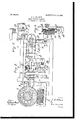
In the accompanying drawings,Figure 1 is a side elevation of the apparatus. Fig. 2 is a transverse section of a portion of the apparatus on the line A A of Fig. 1. Fig. 3 is a similar view on the line B B of Fig. 1.
Referring to the drawings, 1 represents the main power-shaft having bearings 20 in the stationary frame 21. To said shaft 1 power is applied bya belt 2 from any suitable source of power. A belt 3 communicates motion from said shaft 1 to a counter-shaft 4, having bearings 22 in hangers 23, secured by bolts 24 to a frame 8, said frame being supported upon standards 11, pivoted upon beams 25, as shown at 25, so as to permit of transverse oscillations of said standards and of transverse reciprocations of the frame. This transverse reciprocating movement is pro duced-by eccentrics 12 on the shaft 1, revolving in yokes 13, attached to the frame 8, as is common in the art.
The shaft 4 carries at its end a worm 5, meshing with a Worm-wheel 6 on a transverse shaft 7 at the upper end of the frame 8, said shaft also carrying the upper drum 27, around which and also around the lower drum 28 travels the endless coneentratonbelt 9, upon which the values are deposited, said belt passing over rollers 10'on the frame 8. The revolution of the shaft 4 thus produces a slow advance of the belt 9; but in addition to this slow longitudinal advance there is also imparted to the belt 9 a rapid longitudinal reciprocation by means as follows: Upon the counter-shaftel is secured a cam 14, having a flat central surface 19 and a ridge 17, extending outward in the plane of said central sur- 7 both reciprocate in contact with each other transversely with the frame 8. It is evident that with this construction the revolution of the shaft 4 produces a rapid reciprocation of said shaft relative to the frame 8, and therefore a reciprocation of the worm 5, carried by the shaft 4, relative to the wheel 6, carried by the frame 8. This necessarily produces a rapid oscillation of the wheel 6 in addition to its slow rotary motion, and therefore also produces a rapid longitudinal reciprocation of the belt 9 in addition to its slow longitudinal advance. The frame 8, however, does not partake of this longitudinal reciprocation.
The cam 14 is made conical in shape instead of cylindrical, so as to permit of variation of the amplitude of longitudinal reciprocation. By screwing the screw 16 up or down said amplitude may be increased or diminished. When the roller is moved down so far as to contact with the flat central surface 19, no reciprocation whatever results from the revolution of the shaft 14.
I claim 1. In a concentrator, the combination of a shaft, means for revolving said shaft, a Worm thereon,a frame,drums on said frame,an endless concentrating-belt around said drums, a worm-wheel meshing with said worm and 0peratively connected with one of said drums to revolve the same, and positive means inde pendent of the connection with the wormwheel for imparting a longitudinal reciprocation to said shaft, whereby is produced a comparatively rapid oscillation of the wormwheel and a corresponding longitudinal re eiprocation of the belt in addition to its slow advance, substantially as described.
2. In a concentrator, the combination of a shaft, means for revolving said shaft, a worm thereon,a frame ,drums on sa1dframe,an end- 7 less concentrating-belt around said drums, a worrn-wheel meshing with said worm and operatively connected with one of said drums to revolve the same, and means for imparting IIO a longitudinal reciprocation to said shaft, said means comprising a cam on said shaft, and a device engaging said cam, whereby is produced a comparatively rapid oscillation of the worm-wheel and a corresponding longitudinal reciprocation of the belt in addition to its slow advance, substantially as described.
3. In a concentrator, the combination of a shaft, means for revolving said shaft, a Worm thereon, a frame, drums on said frame, an endless concentrating-belt around said drums, a worm-wheel meshing with said Worm and 0peratively connected with one of said drums to revolve the same, and means for imparting a longitudinal reciprocation to said shaft,
said means comprising a conical cam on saidshaft, a roller engaging said cam, and means for adjusting said roller to and from the aXis of the cam, whereby is produced a comparatively rapid oscillation of the worm-Wheel and a corresponding longitudinal reciprocation of the belt in addition to its slow advance, substantially as described.
4. In a concentrator, the combination of a shaft, means for revolving said shaft, a Worm thereon,a frame,drums on said frame,an endless concentrating-belt around said drums, a worm-wheel meshing with said worm and operatively connected With. one of said drums to revolve the same, and means for imparting a longitudinal reciprocation to said shaft, said means comprising a conical cam on said shaft having a flattened central surface, a roller engaging said cam, and means for adjusting said roller to and from the axis of the cam, whereby is produced a comparatively rapid oscillation of the worm-Wheel and a corresponding longitudinal reciprocation of the belt in addition to its slow advance, substantially as described.
5. The combination of a frame, a shaft mounted therein, a worm-wheel on said shaft, a worm engaging said worm-Wheel, a shaft for the worm, bearings therefor secured to said frame, said shaft being slidable in said bearings, means for turning the shaft in said bearings and positive means independent of the connection with the Worm-wheel for reciprocating the shaft therein, whereby, in addition to the slow rotary movement of the Worm-Wheel shaft a comparatively rapid-oscillating movement is imparted thereto, substantially as described.
In witness whereof I have hereunto set my hand in the presence of two subscribing witnesses.
LOUIS R. TULLOCH.
Witnesses F. M. WRIGHT, BESSIE GORFINKEL.
Priority Applications (1)
| Application Number | Priority Date | Filing Date | Title |
|---|---|---|---|
| US19224904A US809648A (en) | 1904-02-05 | 1904-02-05 | Frue concentrator. |
Applications Claiming Priority (1)
| Application Number | Priority Date | Filing Date | Title |
|---|---|---|---|
| US19224904A US809648A (en) | 1904-02-05 | 1904-02-05 | Frue concentrator. |
Publications (1)
| Publication Number | Publication Date |
|---|---|
| US809648A true US809648A (en) | 1906-01-09 |
Family
ID=2878129
Family Applications (1)
| Application Number | Title | Priority Date | Filing Date |
|---|---|---|---|
| US19224904A Expired - Lifetime US809648A (en) | 1904-02-05 | 1904-02-05 | Frue concentrator. |
Country Status (1)
| Country | Link |
|---|---|
| US (1) | US809648A (en) |
-
1904
- 1904-02-05 US US19224904A patent/US809648A/en not_active Expired - Lifetime
Similar Documents
| Publication | Publication Date | Title |
|---|---|---|
| US809648A (en) | Frue concentrator. | |
| US553225A (en) | Pulley-facing machine | |
| US165762A (en) | Improvement in sandpapering-ivjachines | |
| US766878A (en) | Mechanical movement. | |
| US1034302A (en) | Flour-sifter. | |
| US2145226A (en) | Movable fourdrinier suction box assembly | |
| US699539A (en) | Can-testing machine. | |
| US1089633A (en) | Head-motion. | |
| US739877A (en) | Mechanical movement. | |
| US984307A (en) | Middlings-purifier. | |
| US899441A (en) | Suitable apparatus for concentrating and washing minerals. | |
| US476938A (en) | Device for grinding the blades of rotary cylinders | |
| US558978A (en) | Ments | |
| US972415A (en) | Hide-treating machine. | |
| US432873A (en) | Sandpapering-machine | |
| US415454A (en) | Ore-concentrator | |
| US1038919A (en) | Construction and means of operation of pulp-straining drums for paper-making machines. | |
| US710777A (en) | Actuating mechanism for jigs for washing minerals or ores. | |
| US1504307A (en) | Machine for forming grooves | |
| US1019650A (en) | Head-motion for ore-concentrators. | |
| US1905393A (en) | Vibrating screen | |
| US561529A (en) | Chaeles e | |
| US942962A (en) | Gold-saving machine. | |
| US919048A (en) | Belt-tightening and speed-changing mechanism. | |
| US332476A (en) | Burnishing-machine |