US809644A - Elevator-gate. - Google Patents
Elevator-gate. Download PDFInfo
- Publication number
- US809644A US809644A US27315205A US1905273152A US809644A US 809644 A US809644 A US 809644A US 27315205 A US27315205 A US 27315205A US 1905273152 A US1905273152 A US 1905273152A US 809644 A US809644 A US 809644A
- Authority
- US
- United States
- Prior art keywords
- gate
- elevator
- tubes
- catches
- car
- Prior art date
- Legal status (The legal status is an assumption and is not a legal conclusion. Google has not performed a legal analysis and makes no representation as to the accuracy of the status listed.)
- Expired - Lifetime
Links
- 239000002184 metal Substances 0.000 description 1
Images
Classifications
-
- B—PERFORMING OPERATIONS; TRANSPORTING
- B66—HOISTING; LIFTING; HAULING
- B66B—ELEVATORS; ESCALATORS OR MOVING WALKWAYS
- B66B13/00—Doors, gates, or other apparatus controlling access to, or exit from, cages or lift well landings
- B66B13/02—Door or gate operation
- B66B13/14—Control systems or devices
- B66B13/16—Door or gate locking devices controlled or primarily controlled by condition of cage, e.g. movement or position
- B66B13/18—Door or gate locking devices controlled or primarily controlled by condition of cage, e.g. movement or position without manually-operable devices for completing locking or unlocking of doors
- B66B13/20—Lock mechanisms actuated mechanically by abutments or projections on the cages
Definitions
- My invention relates to an improvement in elevator-gates.
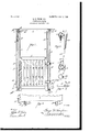
- FIG. 1 is a front elevation, partly in section.
- Fig. 2 is a section on line w w, with the gate removed, showing the elevator at trip ping position.
- Fig. 3 is in the nature of a plan view, partly in section, illustrating means for yieldingly connecting the tube rotatively.
- Fig. 4 is an enlarged lan view of one of the tubes.
- Fig. 5 is an enc elevation of the elevator-cam.
- 1 represents the elevator-gate.
- each tube 2 represents a portion of the elevator-car.
- 3 4 represent outside tubes forming the opposite sides of the doorway. They are provided at the top with the sheaves 5 6, over which pass the ropes 7 8, each having a counterbalance 9 within the tube.
- the tubes 3 and 4 have the catches 1O 11., respectively, at the top and 12 13 at the bottom.
- each tube has the top catch and the bottom catch projected radially from the tube in different vertical lines, so that both are disclosed from a top plan view. with the top latches 14 15, adapted to 006perate with the top catches 1 1 and with the bottom latches 16 17, adapted to cooperate with the bottom catches 12 13, respectively.
- the tubes are journaled in the plates 18 19 at the top, respectively, and plates 18 19 at the bottom, so that each is slightly rotatable on its axis.
- the tubes are provided with the cars 20 21, connected by a cross-bar 22.
- the sheave 5 is journaled in plate 18.
- the car or platform is provided with a cam 24, (see Figs. 2 and 5,) and one of the tubes, say 3,has an arm 25 with an antiiriction-roller 26 in position to be engaged by the cam 24, which The elevator-gate is providedv will deflect the said arm 25 and turn said tubes in their bearings, moving the catches 12 and 13 out of engagement with the latches 16 and 17, so that the door may be raised and turn the top catches 10 and 11 into position to be engaged by the top catches 14 and 15 to automatically catch and lock the gate in raised position.
- the cam 24 and the arm 25 are so positioned relatively as to operate this trip when the car is at the level of the floor upon which the gate is to be manipulated.
- the gate is provided with the laterally-em tending metal bands 30 31 32 33 at the top and bottom, respectively, which are looped around the tubes 3 4, and thus form vertical guides for the gate.
- the tubes are set inside of the walls forming the gateway, and they form a very simple but light and strong mounting for the gate.
- I claim 1 In combination with an elevator-car, a vertically-sliding counterbalanced gate, having top and bottom latches, a rotatable member having top and bottom catches in diflerent vertical lines, and means actuated by the car to rotate said member whereby one of thecatches is moved out and the other into position for engagement with its cooperating latch on the gate, substantially as described.
- a vertically-sliding counterbalanced gate having top and bottom latches, a rotatable member having corresponding top and bottom catches projected in .dili'erent vertical lines, means for holding said rod yieldingly in normal position with the bottom catch and latch in engagement, and means actuated by the car for rotating said member to release the bottom catch and to throw the top catch into position for engaging the top catch when the gate is raised, substantially as described.
- a vertically-sliding gate having top and bottom latches, a rotatable tube at the side of the gateway, a counterbalance for the gate sliding in said tube, a top and bottom catch radially projected from the tube .in different vertical lines, means for holding said tube in the given position yieldingly, and means actuated by the car for turning said tube to release one catch and latch and engage another, substantially as described.
- a vertically-sliding gate having top and bottom latches on each side, a rotatable tube on each side of the gateway, counterbalances for said gate sliding in said tubes, top and bottom catches on each tube radially projected in different vertical lines, means connecting said tubes whereby they rotate in unison, means for holding said tubes yieldingly in a given position, and means actuated by the car for rotating said tubes whereby one set of catches and latches are released and the other set of catches thrown into position to engage their cooperating latches, substantially as described.
- a vertically-sliding gate having latches, a rotatable member having catches in different vertical lines, and means actuated by the car to rotate said member whereby the catches are moved. into and out of position, substan tially as described.
- vertically sliding gate having latches, rotatable members having catches in different vertical lines, vertical guide connections between said members and the gate, and means actuated by the car to operate said catches, substantially as described.
- a sliding gate between said tubes having counterbalances sliding Within said tubes, said tubes having catches extending radially in different vertical lines, cooperating latches on the gate, and vertical guide connections projected from the gate and engaging around the tubes, substantially as described.
Landscapes
- Engineering & Computer Science (AREA)
- Mechanical Engineering (AREA)
- Automation & Control Theory (AREA)
- Cage And Drive Apparatuses For Elevators (AREA)
- Lift-Guide Devices, And Elevator Ropes And Cables (AREA)
- Types And Forms Of Lifts (AREA)
Description
No. 809,644. PATENTED JAN. 9, 190B.
' G. D. THOMPSON.
ELEVATOR GATE.
APPLICATION FILED AUG. 7, 1905.
E a 19 awzntoz GEORGE D. THOMPSON, OF ARLINGTON HEIGHTS, OHIO.
ELEVATOR-GATE.
Specification of Letters Patent.
Patented Jan. 9, 1906.
Application fil Aug '7, 1905. Serial No. 273,152.
To (all whom, it may concern:
Be it known that I, GEORGE D. THOMPSON, a citizen of the United States, residing at Arlington Heights, in the county of Hamilton and State of Ohio, have invented certain new and useful Improvements in Elevator- Gates, of which the following is a specificatlon.
My invention relates to an improvement in elevator-gates.
The features of the invention are more fully set forth in the description of the accompanying drawings, forming a part of this specification, in which Figure 1 is a front elevation, partly in section. Fig. 2 is a section on line w w, with the gate removed, showing the elevator at trip ping position. Fig. 3 is in the nature of a plan view, partly in section, illustrating means for yieldingly connecting the tube rotatively. Fig. 4 is an enlarged lan view of one of the tubes. Fig. 5 is an enc elevation of the elevator-cam.
1 represents the elevator-gate.
2 represents a portion of the elevator-car. 3 4 represent outside tubes forming the opposite sides of the doorway. They are provided at the top with the sheaves 5 6, over which pass the ropes 7 8, each having a counterbalance 9 within the tube. The tubes 3 and 4 have the catches 1O 11., respectively, at the top and 12 13 at the bottom. As shown in Fig. 4, it will be seen that each tube has the top catch and the bottom catch projected radially from the tube in different vertical lines, so that both are disclosed from a top plan view. with the top latches 14 15, adapted to 006perate with the top catches 1 1 and with the bottom latches 16 17, adapted to cooperate with the bottom catches 12 13, respectively. The tubes are journaled in the plates 18 19 at the top, respectively, and plates 18 19 at the bottom, so that each is slightly rotatable on its axis. The tubes are provided with the cars 20 21, connected by a cross-bar 22. The sheave 5 is journaled in plate 18.
23 represents a coil-spring connecting the bar 22 with the plate 18 and holding the tube normally in a given position, in which catches 12 13 are in position to engage the latches 16 17 to hold the elevator-gate down. The car or platform is provided with a cam 24, (see Figs. 2 and 5,) and one of the tubes, say 3,has an arm 25 with an antiiriction-roller 26 in position to be engaged by the cam 24, which The elevator-gate is providedv will deflect the said arm 25 and turn said tubes in their bearings, moving the catches 12 and 13 out of engagement with the latches 16 and 17, so that the door may be raised and turn the top catches 10 and 11 into position to be engaged by the top catches 14 and 15 to automatically catch and lock the gate in raised position. The cam 24 and the arm 25 are so positioned relatively as to operate this trip when the car is at the level of the floor upon which the gate is to be manipulated.
It will be noted that this device is extremely simple, the parts are cliicient in operation, and occupy but little space.
The gate is provided with the laterally-em tending metal bands 30 31 32 33 at the top and bottom, respectively, which are looped around the tubes 3 4, and thus form vertical guides for the gate. The tubes are set inside of the walls forming the gateway, and they form a very simple but light and strong mounting for the gate.
Having described my invention, I claim 1. In combination with an elevator-car, a vertically-sliding counterbalanced gate, having top and bottom latches, a rotatable member having top and bottom catches in diflerent vertical lines, and means actuated by the car to rotate said member whereby one of thecatches is moved out and the other into position for engagement with its cooperating latch on the gate, substantially as described.
2. In combination with an elevator-car, a vertically-sliding counterbalanced gate, having top and bottom latches, a rotatable member having corresponding top and bottom catches projected in .dili'erent vertical lines, means for holding said rod yieldingly in normal position with the bottom catch and latch in engagement, and means actuated by the car for rotating said member to release the bottom catch and to throw the top catch into position for engaging the top catch when the gate is raised, substantially as described.
3. In combination with an elevator-car, a vertically-sliding gate, having top and bottom latches, a rotatable tube at the side of the gateway, a counterbalance for the gate sliding in said tube, a top and bottom catch radially projected from the tube .in different vertical lines, means for holding said tube in the given position yieldingly, and means actuated by the car for turning said tube to release one catch and latch and engage another, substantially as described.
4. In combination with an elevator-car, a vertically-sliding gate having top and bottom latches on each side, a rotatable tube on each side of the gateway, counterbalances for said gate sliding in said tubes, top and bottom catches on each tube radially projected in different vertical lines, means connecting said tubes whereby they rotate in unison, means for holding said tubes yieldingly in a given position, and means actuated by the car for rotating said tubes whereby one set of catches and latches are released and the other set of catches thrown into position to engage their cooperating latches, substantially as described.
5. In combination with an elevator-car, a vertically-sliding gate having latches, a rotatable member having catches in different vertical lines, and means actuated by the car to rotate said member whereby the catches are moved. into and out of position, substan tially as described.
6. In combination with an elevator-car, a
vertically sliding gate having latches, rotatable members having catches in different vertical lines, vertical guide connections between said members and the gate, and means actuated by the car to operate said catches, substantially as described.
7. In combination with an elevator-car, vertical tubes rotatably mounted in the sides of the gateway, a sliding gate between said tubes having counterbalances sliding Within said tubes, said tubes having catches extending radially in different vertical lines, cooperating latches on the gate, and vertical guide connections projected from the gate and engaging around the tubes, substantially as described.
In. testimony whereof I have hereunto set my hand.
GEORGE D. THOMPSON.
i tnesses S. Ross, LEO ODoNNELL.
Priority Applications (1)
| Application Number | Priority Date | Filing Date | Title |
|---|---|---|---|
| US27315205A US809644A (en) | 1905-08-07 | 1905-08-07 | Elevator-gate. |
Applications Claiming Priority (1)
| Application Number | Priority Date | Filing Date | Title |
|---|---|---|---|
| US27315205A US809644A (en) | 1905-08-07 | 1905-08-07 | Elevator-gate. |
Publications (1)
| Publication Number | Publication Date |
|---|---|
| US809644A true US809644A (en) | 1906-01-09 |
Family
ID=2878125
Family Applications (1)
| Application Number | Title | Priority Date | Filing Date |
|---|---|---|---|
| US27315205A Expired - Lifetime US809644A (en) | 1905-08-07 | 1905-08-07 | Elevator-gate. |
Country Status (1)
| Country | Link |
|---|---|
| US (1) | US809644A (en) |
-
1905
- 1905-08-07 US US27315205A patent/US809644A/en not_active Expired - Lifetime
Similar Documents
| Publication | Publication Date | Title |
|---|---|---|
| US809644A (en) | Elevator-gate. | |
| US490328A (en) | Safety device for platform-elevators | |
| US890071A (en) | Safety-door for elevators. | |
| US840754A (en) | Elevator-door-opening device. | |
| US1798578A (en) | Locking device | |
| US408509A (en) | Device for operating elevator-doors | |
| US279612A (en) | Elevator-hatch | |
| US952966A (en) | Door-operating mechanism for street-cars. | |
| US581860A (en) | Elevator-lock | |
| US909602A (en) | Sliding-door construction. | |
| US1035761A (en) | Elevator-door controller. | |
| US1221543A (en) | Elevator protective apparatus. | |
| US969296A (en) | Elevator safety device. | |
| US576144A (en) | Device for automatically locking elevators | |
| US651562A (en) | Elevator. | |
| US305000A (en) | Automatic elevator-guard | |
| US1133332A (en) | Lock for car-doors. | |
| US979808A (en) | Locking and signaling device. | |
| US537324A (en) | Thirds to edward w | |
| US762455A (en) | Lock for elevator-doors. | |
| US793452A (en) | Automatic mine-door. | |
| US1237841A (en) | Hatch-covering. | |
| US731676A (en) | Door operating and locking mechanism. | |
| US1100304A (en) | Safety appliance for mine-hoists. | |
| USRE11402E (en) | Safety device for elevators |