US8096156B2 - Forming of metal container bodies - Google Patents
Forming of metal container bodies Download PDFInfo
- Publication number
- US8096156B2 US8096156B2 US11/980,283 US98028307A US8096156B2 US 8096156 B2 US8096156 B2 US 8096156B2 US 98028307 A US98028307 A US 98028307A US 8096156 B2 US8096156 B2 US 8096156B2
- Authority
- US
- United States
- Prior art keywords
- container bodies
- path
- holders
- tool sets
- open
- Prior art date
- Legal status (The legal status is an assumption and is not a legal conclusion. Google has not performed a legal analysis and makes no representation as to the accuracy of the status listed.)
- Active, expires
Links
- 229910052751 metal Inorganic materials 0.000 title claims abstract description 34
- 239000002184 metal Substances 0.000 title claims abstract description 34
- 238000000034 method Methods 0.000 claims abstract description 12
- 238000012546 transfer Methods 0.000 claims description 43
- 238000007493 shaping process Methods 0.000 claims description 7
- 230000000717 retained effect Effects 0.000 claims description 3
- 230000002093 peripheral effect Effects 0.000 description 6
- 238000004519 manufacturing process Methods 0.000 description 5
- 239000000463 material Substances 0.000 description 5
- 230000009467 reduction Effects 0.000 description 5
- 230000008569 process Effects 0.000 description 4
- 229910000831 Steel Inorganic materials 0.000 description 3
- 230000008859 change Effects 0.000 description 3
- 239000010959 steel Substances 0.000 description 3
- 229910052782 aluminium Inorganic materials 0.000 description 2
- XAGFODPZIPBFFR-UHFFFAOYSA-N aluminium Chemical compound [Al] XAGFODPZIPBFFR-UHFFFAOYSA-N 0.000 description 2
- 235000013361 beverage Nutrition 0.000 description 2
- 238000007796 conventional method Methods 0.000 description 2
- 238000005516 engineering process Methods 0.000 description 2
- 230000009471 action Effects 0.000 description 1
- 239000000443 aerosol Substances 0.000 description 1
- 238000011161 development Methods 0.000 description 1
- -1 ferrous metals Chemical class 0.000 description 1
- 238000012423 maintenance Methods 0.000 description 1
- 230000007246 mechanism Effects 0.000 description 1
- 230000005019 pattern of movement Effects 0.000 description 1
- 230000008439 repair process Effects 0.000 description 1
- 239000000126 substance Substances 0.000 description 1
- 230000000007 visual effect Effects 0.000 description 1
- 230000037303 wrinkles Effects 0.000 description 1
Images


Classifications
-
- B—PERFORMING OPERATIONS; TRANSPORTING
- B23—MACHINE TOOLS; METAL-WORKING NOT OTHERWISE PROVIDED FOR
- B23Q—DETAILS, COMPONENTS, OR ACCESSORIES FOR MACHINE TOOLS, e.g. ARRANGEMENTS FOR COPYING OR CONTROLLING; MACHINE TOOLS IN GENERAL CHARACTERISED BY THE CONSTRUCTION OF PARTICULAR DETAILS OR COMPONENTS; COMBINATIONS OR ASSOCIATIONS OF METAL-WORKING MACHINES, NOT DIRECTED TO A PARTICULAR RESULT
- B23Q7/00—Arrangements for handling work specially combined with or arranged in, or specially adapted for use in connection with, machine tools, e.g. for conveying, loading, positioning, discharging, sorting
- B23Q7/02—Arrangements for handling work specially combined with or arranged in, or specially adapted for use in connection with, machine tools, e.g. for conveying, loading, positioning, discharging, sorting by means of drums or rotating tables or discs
-
- B—PERFORMING OPERATIONS; TRANSPORTING
- B21—MECHANICAL METAL-WORKING WITHOUT ESSENTIALLY REMOVING MATERIAL; PUNCHING METAL
- B21D—WORKING OR PROCESSING OF SHEET METAL OR METAL TUBES, RODS OR PROFILES WITHOUT ESSENTIALLY REMOVING MATERIAL; PUNCHING METAL
- B21D51/00—Making hollow objects
- B21D51/16—Making hollow objects characterised by the use of the objects
- B21D51/26—Making hollow objects characterised by the use of the objects cans or tins; Closing same in a permanent manner
- B21D51/2615—Edge treatment of cans or tins
-
- B—PERFORMING OPERATIONS; TRANSPORTING
- B21—MECHANICAL METAL-WORKING WITHOUT ESSENTIALLY REMOVING MATERIAL; PUNCHING METAL
- B21D—WORKING OR PROCESSING OF SHEET METAL OR METAL TUBES, RODS OR PROFILES WITHOUT ESSENTIALLY REMOVING MATERIAL; PUNCHING METAL
- B21D51/00—Making hollow objects
- B21D51/16—Making hollow objects characterised by the use of the objects
- B21D51/26—Making hollow objects characterised by the use of the objects cans or tins; Closing same in a permanent manner
- B21D51/2692—Manipulating, e.g. feeding and positioning devices; Control systems
Definitions
- the present invention relates to methods of and apparatus for producing containers. More particularly, the invention relates to forming operations carried out on open-ended container bodies during the manufacture of containers, for example die necking, shaping (expansion), flanging, and similar forming operations.
- die-necking as an example of the type of forming operations that may be carried out, but it should be kept in mind that the present invention is not limited solely to die-necking operations.
- the technology for modifying an open-ended portion of a closed end container has been in existence for over one hundred years.
- the procedure was originally developed for artillery shells, with a larger diameter shell casing being reduced at the open end to retain a smaller diameter projectile.
- the process by which this is accomplished today is called die-necking.
- the basic concept of necking is to take a typically cylindrical, thin walled metal container body or shell having a given diameter and physically push the open end into a die or series of progressively smaller dies. In the course of this process, a reduction in diameter of the open end is realized.
- Containers of this kind are normally produced by manufacturing an open-ended container body, and then closing the container body with an end panel. Because the end panel is normally of a thickness that is greater than the thickness of a typical sidewall, as the diameter of the container body is reduced at the open end, the amount of material required for the end panel is reduced by a greater amount.
- the necking operation is performed to bring the opening to a specific diameter to accommodate a standard size valve assembly and to eliminate any secondary adaptor that would otherwise be necessary to accommodate differences of size.
- a second consideration in such operations is the reduction in the longitudinal stress exerted on the end of the container when the container is filled with a substance under pressure. As the end wall size is reduced, the total force it encounters at a given pressure is reduced and the end wall can thus be reduced further in thickness.
- a third consideration for diameter reduction is visual. Many aesthetically pleasing container shapes can be achieved by necking conventional cylindrical shapes into tapered geometries and containers that resemble bottles.
- U.S. Pat. No. 5,355,710 discloses a conventional method and apparatus for necking a metal container. The disclosure of this patent is specifically incorporated herein by reference.
- U.S. Pat. No. 5,768,931 discloses an apparatus having a number of planetary turrets that rotate on their own axes through a series of indexed positions. Tools engage a workpiece held in a planetary turret at successive workstations.
- An exemplary embodiment of the present invention provides apparatus for forming open ends of open-ended metal container bodies, the apparatus comprising a plurality of movable holders separated by substantially equal spacings from each other, each holder being adapted to receive and temporarily retain an open-ended metal container body therein with an open-end of the container body exposed to allow forming thereof, the holders being adapted to move a plurality of the container bodies along a path in the apparatus; a drive motor adapted and controlled to advance the holders in steps of advancement with pauses therebetween, each step producing an advancement that is the same for each step and is equivalent to a multiple of two or more of the spacings between the holders; at least one group of two or more tool sets positioned adjacent to the path and separated from each other along the path by distances equivalent to the spacings between the holders, each tool set being adapted for forming an open end of a container body aligned therewith, and each group having a number of tool sets that is the same as the multiple of the spacings employed for the steps of advancement.
- Another exemplary embodiment provides a method of shaping open ends of open-ended metal container bodies, comprising advancing a plurality of open-ended metal container bodies along a path in steps of advancement with pauses therebetween, each step producing a movement of container bodies along the path corresponding to an advancement of two or more container bodies; engaging a plurality of tool sets acting as a group during the pauses with open ends of adjacent container bodies, thereby forming the open ends of the container bodies, the plurality of tool sets engaged as the group being equal in number to the container bodies advanced along the path during each step; and removing container bodies at an end of the path.
- all of the tool sets of the group are chosen and operated to carry out identical forming operations on the container bodies.
- a further exemplary embodiment provides apparatus for forming open ends of open-ended metal container bodies, the apparatus comprising a plurality of movable holders, each holder being adapted to receive and temporarily retain an open-ended metal container body therein with an open-end of the container body exposed to allow forming thereof, the holders being constrained to move a plurality of the container bodies along a path extending through the apparatus; a drive motor adapted for advancing the container bodies retained within the holders along the path in steps of advancement with pauses therebetween, each step producing a movement of container bodies along the path corresponding to an advancement of one or more container bodies; at least one group of work stations positioned adjacent to the path, each work station of the at least one group having a tool set for forming an open end of a container body aligned therewith; an actuator for engaging the tool sets of the at least one group of work stations with an aligned container body during pauses between the steps of advancement; a feed device adapted to feed open-ended container bodies individually to the plurality of movable holders at a start
- a star wheel for use with apparatus for forming open ends of open-ended metal container bodies, the star wheel comprising a hub adapted for rotation about a central axis; a rim spaced from the hub; means, such as spokes, interconnecting the hub and the rim; a plurality of holders for container bodies spaced evenly around the rim; and means for holding the container bodies temporarily in the holders at the rim; wherein the holders are detachable from the star wheel and replaceable by other holders.
- the holders are preferably depressions formed in a peripheral ring attached to the rim, and the ring is detachable from the rim and replaceable by a different ring having the other holders formed therein.
- a still further exemplary embodiment provides apparatus for forming open ends of open-ended metal container bodies, the apparatus comprising: a plurality of movable holders for container bodies constrained to move the bodies in a path in the apparatus; a first apparatus unit on one side of the path; and a second apparatus unit on an opposite side of the path, wherein the first and second units confront each other across the path and carry tool sets that cooperate to achieve forming of container bodies held between the units by the holders in the path; wherein at least one of the first and second apparatus units is adapted for movement to vary distance between the units.
- a still further exemplary embodiment provides apparatus for forming open ends of open-ended metal container bodies, the apparatus comprising a plurality of movable holders separated by substantially equal spacings from each other, each holder being adapted to receive and temporarily retain an open-ended metal container body therein with an open-end of the container body exposed to allow forming thereof, the holders being adapted to move a plurality of the container bodies along a non-circular path in the apparatus; a drive motor adapted and controlled to advance the holders in steps of advancement with pauses therebetween, each step producing an advancement that is the same for each step and is equivalent to one or more of the spacings between the holders; two or more tool sets positioned adjacent to the path and separated from each other along the path by distances equivalent to at least one of the spacings between the holders, each tool set being adapted for shaping an open end of a container body aligned therewith.
- the tool sets preferably comprise tubular necker dies, knockout shafts movable within the necker dies, and pusher rods for pushing container bodies into the
- a group of tool sets provided at consecutive workstations contains at least two tool sets, and preferably considerably more, e.g. 4, 6 or 8.
- two or more container bodies may be worked on simultaneously, and thus the throughput of the apparatus can be increased compared to apparatus carrying out a single operation on can bodies one at a time.
- FIG. 1 is a simplified side view of a part of an apparatus according to one exemplary embodiment with certain equipment removed for clarity;
- FIG. 2 is a top plan view of the apparatus of FIG. 1 showing, in addition to the features of FIG. 1 , some of the apparatus not visible in that view;
- FIG. 3 is a top plan view of a movable carriage for elements shown in FIGS. 1 and 2 ;
- FIG. 4 is a front elevation of the carriage of FIG. 3 ;
- FIG. 5 is a vertical cross-section through a star wheel forming part of the apparatus of FIGS. 1 and 2 ;
- FIG. 6 is an exploded view of the star wheel shown in FIG. 5 ;
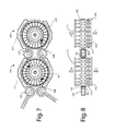
- FIGS. 7 and 8 are views similar to FIGS. 1 and 2 , respectively, of another exemplary embodiment
- FIG. 9 is a top plan view of yet another exemplary embodiment.
- FIGS. 10 , 11 and 12 are, respectively, an end view, a side view and a top plan view of an embodiment similar to that of FIG. 9 , showing more detail but with some parts omitted for clarity: and
- FIG. 13 is a perspective view of an apparatus based on that of FIGS. 1 and 2 , but showing equipment that makes part of the apparatus movable for improved access during maintenance and the like.
- FIG. 1 of the accompanying drawings shows an exemplary embodiment 100 in partial view and simplified schematic form. In particular, supporting framework has been omitted for clarity.
- the drawing shows a vertical elevation of a die necker apparatus viewed along the line I-I of the top plan view of FIG. 2 .
- This part of the apparatus is sometimes referred to as a turret, and includes a star wheel 101 having a central hub 109 , a series of spokes 121 , and a rim 102 supporting a peripheral ring 103 shaped to form a series of twenty four container body holders 104 spaced evenly around the periphery of the wheel 101 .
- Each of the holders 104 is a semi-cynlindrical depression in the outer surface of the peripheral ring 103 dimensioned to snugly receive an open-ended cylindrical container body 105 (e.g. an aluminum or steel beverage can body) when oriented with its axis parallel to the rotational axis of the star wheel about the hub 109 .
- the container bodies are individually fed to the star wheel 101 by a feeder (infeed) transfer wheel 107 as the star wheel rotates in a clockwise direction (as shown by arrows A, B and C).
- Container bodies 105 are ultimately removed from the star wheel by removal (discharge) transfer wheel 108 .
- the container bodies 105 are held in place in the holders 104 during the rotation of the star wheel 101 , and in similar holders in the feeder and removal transfer wheels 107 and 108 , by means of suction applied through holes provided in inner surfaces of the holders 104 (as will be explained more fully later).
- suction may be incorporated into the holders 104 when the apparatus is intended for use with container bodies made of steel or other ferrous metals.
- the star wheel 101 is rotated by a drive motor (not shown in FIGS. 1 and 2 ) in a stepwise or indexed manner such that the wheel is repeatedly advanced by equal amounts between short pauses of non-rotation.
- the star wheel is rotated during each period of advancement by a distance corresponding to the advancement of eight holders 104 or container bodies 105 , i.e. by one third of a turn or 120° (although, in other embodiments, the rotation could be more or less).
- container bodies 105 are advanced in groups of eight during each rotational step such that, as the star wheel is first loaded from feeder transfer wheel 107 (which acts as a container body feed device), a first group of eight container bodies 105 is introduced into the holders 104 at the top part of the star wheel in the first rotational step (as shown by arrow A), then, after a short pause, these eight container bodies move with the holders to the four holder positions on the right side of the star wheel and four holder positions at the bottom part of the wheel (arrow B).
- the leading four container bodies of this first group are removed by the removal transfer wheel 108 (acting as a container body removal device), and the trailing four container bodies of the first group are moved to occupy holder positions at the lower part of the star wheel 101 immediately adjacent to the transfer wheel 108 (arrow C, the dashed part of which corresponds to the removal of container bodies from the star wheel).
- the star wheel is fully loaded with container bodies around its periphery.
- groups of eight new container bodies 105 are introduced into the holders 104 by feeder transfer wheel 107 at each stepwise turn, eight container bodies are removed from the star wheel by removal transfer wheel 108 .
- Additional container bodies are supplied to feeder transfer wheel 107 via a chute 140 and processed container bodies are removed from removal transfer wheel 108 via chute 141 . It will be noticed that most or all of the four holder positions at the left side of the star wheel 101 are not occupied by container bodies because they are positioned between the feeder transfer wheel 107 and the removal transfer wheel 108 .
- the movement of the container bodies through the apparatus from the feeder transfer wheel 107 to the removal transfer wheel 108 is referred to as the path followed by the container bodies in the apparatus.
- the path is part-circular and includes the periphery of the star wheel between the feeder and removal transfer wheels.
- the holders 104 are themselves confined to follow a circuit (in this case circular) completely around the periphery of the star wheel as the star wheel rotates.
- a group of eight work stations are provided at the top of the wheel and another group of eight workstations are provided at the bottom of the wheel. These work stations are merely fixed locations spaced around the wheel that come into register with particular container holders as the wheel pauses between each rotational step, and they are locations where tool sets for forming the container body are positioned.
- the tool sets consist of pusher rods 110 on one side of the wheel and combinations of tubular necker dies 115 and knockout shafts 116 on the other side of the wheel (see FIG. 2 ).
- the pusher rods 110 at all of the eight workstations at the top of the wheel are rigidly connected to a movable pusher rod frame element 111 having a shallow inverted approximately “V” shape.
- pusher rods 110 at the workstations at the bottom of the wheel are each rigidly connected to a second movable pusher rod frame element 111 ′ (also of shallow inverted approximately “V” shape).
- the pusher rod frame elements 111 and 111 ′ are moved in the directions of double-headed arrow D towards and away from the star wheel during each rotational pause of the star wheel by a drive means described in more detail later. Since the two groups of pusher rods 110 are rigidly attached to their respective pusher rod frame elements, they move in unison with those elements and with the other rods of the group.
- tubular necker dies 115 On the other side of the wheel, there are eight tubular necker dies 115 at the workstations at the top of the wheel, and eight tubular necker dies 115 at the workstations at the bottom of the wheel. These necker dies do no move at all as they are rigidly attached to a stationary frame element 117 forming part of the apparatus frame (not shown). Each necker die 115 is provided with a knockout shaft 116 that projects into the tubular necker die from the rear (the part most distant from the star wheel).
- the outermost ends of the eight knockout shafts 116 occupying the workstations at the top of the wheel are rigidly connected to a movable knockout shaft frame element 118 , and similarly, the eight knockout shafts 116 occupying the workstations at the bottom of the wheel are each connected to a second knockout shaft frame element (not visible in FIGS. 1 and 2 , but positioned facing frame 111 ′ on the opposite side of the star wheel).
- These movable frame elements are moved by drive means (described in more detail later) towards and away from the star wheel in the directions shown by double headed arrow E during each rotational pause of the star wheel.
- knockout shafts 116 are all rigidly attached either to knockout shaft frame element 118 at the top of the wheel or to the equivalent element at the bottom of the wheel, they move in unison with their respective frame elements and with the other knockout shafts of their respective group.
- the tool sets at all the workstations around the wheel are operated to carry out a shaping (die necking) operation on the container bodies brought into alignment with the tool sets by the star wheel.
- a shaping (die necking) operation may be equivalent to those disclosed in U.S. Pat. No. 7,073,365 which issued on Jul. 11, 2006 to Geho et al. (the disclosure of which is incorporated herein by reference).
- This patent describes a linear drive metal forming machine operated under computer numerical control.
- a knockout shaft is first introduced into a container body through the open end and the end of the container is then forced into a convergent forming die by a pusher rod pushing on the opposite (closed) end of the container body.
- a gas under pressure is also introduced into the container through the knockout shaft (to stiffen the container body), and the knockout shaft is then withdrawn as the open end of the container body is shaped by the die. This same kind of operation may be carried out in the embodiment of FIGS.
- the knockout shaft frame elements 118 and the equivalent element at the bottom of the wheel are moved towards the star wheel through the tubular necker dies 115 in readiness to enter aligned container bodies.
- the container bodies 105 are then pushed into the open ends of the necker dies 115 by the movement of pusher rods 110 driven by the movement of the frame elements 111 and 111 ′ towards the star wheel.
- the knockout shafts enter the container bodies and deliver gas under pressure, and are then withdrawn from the containers by movement of the knockout shaft frame elements 118 away from the star wheel as the shaping of the necking of the container bodies is completed.
- the container bodies are returned to their starting positions in the holders 104 by combined action of the knockout shafts (moving again towards the star wheel) and/or by the gas pressure within the container bodies.
- the container bodies are consequently disengaged from the tool sets at this point and the star wheel is free to make another rotation of one third of a complete turn, thereby bringing additional container bodies into register with the tool sets.
- the tool sets (necker dies, knockout shafts and pusher rods) within each group of workstations are preferably identical to each other, but the tool sets of the two groups differ from each other or are operated differently.
- the necker dies 115 at the bottom of the star wheel may have narrower die openings than those at the top so that a container is progressively necked inwardly to form an ever-narrower opening as the container body advances around the star wheel, or alternatively, the pusher rods at the bottom may have a longer “throw” to push the container bodies deeper into the necker dies than those of the top group, thereby achieving a greater degree of necking.
- each container body undergoes just two die necking operations as it follows the path around the star wheel, one at a workstation at the top of the wheel and one at a workstation at the bottom of the wheel.
- sixteen container bodies are necked simultaneously at each pause of the wheel. The throughput of the apparatus is therefore much higher than when containers are necked individually (e.g. in the apparatus of the Geho et al. patent mentioned above).
- each group is not essential and there may be more or fewer.
- the tool sets of each group should all be the same and should be operated in the same way to produce identical necking operations on the container bodies.
- Tool sets of different groups would then be different from each other or operated in different ways.
- each tool set of a group could be different from the other so that adjacent container bodies aligned with the group are formed in different ways.
- the next set of tool sets positioned around the star wheel could then also have different tool sets (or operations) in each position.
- the end result at the completion of each part rotation would be the removal from the star wheel of eight container bodies formed (necked) in different ways from each other (i.e. eight different products) which would then be separated from each other further down the production line.
- a further alternative would be to have some tool sets of one group the same and others different, as required for particular product lines.
- the star wheel is advanced by a number of holders corresponding to the number of tool sets in each group, but again this is not essential, particularly if the tool sets of the same group differ from each other.
- the star wheel is advanced by at least two holders at each rotational step, although there are circumstances in which it may be desirable to advance the holders one at a time, and to provide a plurality of individual tool sets that carry out two or more different forming operations on the container bodies, one at each step of advancement.
- the pusher rod frame elements and knockout shaft frame elements 111 , 111 ′ and 118 , etc. may be moved back and forth in the directions of arrows D and E by any suitable drive means, such as hydraulic or pneumatic piston and cylinder combinations, preferably under computer numerical control.
- the drive means consist of linear electric motors because such motors are compact, quick acting, forceful and easily controllable.
- FIGS. 3 and 4 of the accompanying drawings An example of the use of linear electric motors is illustrated in FIGS. 3 and 4 of the accompanying drawings, FIG. 3 being a top plan view similar to that of FIG. 2 , but showing only one pusher rod frame element 111 , the accompanying pusher rods 110 , and associated parts.
- FIG. 3 being a top plan view similar to that of FIG. 2 , but showing only one pusher rod frame element 111 , the accompanying pusher rods 110 , and associated parts.
- FIG. 3 being a top plan view similar to that of FIG. 2 , but showing only one pusher rod
- FIG. 4 is a vertical elevation of the frame element of FIG. 3 viewed from the front (i.e. the side supporting the pusher rods 110 ).
- the pusher rod frame element 111 forms part of a carriage 119 in which the pusher rod frame element is aligned with a similar element 112 and rigidly attached thereto by connecting rods 113 .
- the carriage 119 supports a pair of flat metal plates 114 at its upper sloping sides, the plates being attached to the carriage 119 by suitable connectors.
- the carriage has longitudinal rails 106 provided with lateral grooves which support the carriage in elongated sliding bearings (not shown) fixed to the supporting frame of the apparatus.
- the sliding bearings incorporate ball bearings that engage the lateral grooves of the rails, thus making the carriage slidable back and forth relative to the remainder of the apparatus as shown by arrow D.
- Attached to the supporting frame of the apparatus are a pair of flat stationary linear drive elements 130 facing the flat metal plates 114 . Together, the plates 114 and the elements 130 form linear electric motors, and current passing through the drive elements drives the plates (and hence the carriage 119 ) in one direction or the other along rails 106 according to the polarity of the current.
- the application of the current or voltage is kept under computer numerical control, so that the movement of the framework can be made to follow a pre-determined pattern of movement suitable for the intended necking operations.
- Each of the other pusher rod or knockout shaft frame elements 111 ′, 118 , etc. are also supported in the same way and each is provided with its own equivalent linear electric drive motors controlled by computer.
- FIGS. 5 and 6 show the star wheel 101 of FIGS. 1 and 2 in vertical cross-section ( FIG. 3 ) and in exploded form ( FIG. 4 ).
- Each of the container body holders 104 is provided with at least one bore 120 connected via hollow spokes 121 to a central hub 109 .
- a sidewall 123 of the hub is provided with a series of holes 124 which connect through the hub 109 to individual hollow spokes 121 .
- a wear plate 125 is fixed over the sidewall and rotates with it, and this too has holes that register with those in the sidewall. The purpose of the wear plate 125 is to protect the star wheel (usually made of relatively soft aluminum) from excessive wear caused by contact with a vacuum manifold 122 .
- the wear plate is made of a more wear-resistant metal, e.g. steel.
- the vacuum manifold 122 remains stationary and the wear plate 125 and sidewall 123 rotate with the star wheel 101 .
- the vacuum manifold (which has an internal channel open to the wear plate 125 ) is connected to a vacuum pump (not shown) and is dimensioned to cover part of the wear plate, so that air may be withdrawn through the bores 120 of holders 104 when in particular positions around the periphery of the star wheel 101 .
- a vacuum pump not shown
- the container body When the vacuum is broken as the holder moves to a position where it is not connected to the vacuum pump via the vacuum manifold 122 , the container body may be removed from the holder without difficulty, e.g. by transfer to a similar holder in removal transfer wheel 108 . The holder in the removal transfer wheel 108 would then be subjected to vacuum in a similar way (via the transfer wheel's own similar suction arrangement), thus making the transfer operation slippage-free.
- the same arrangement is provided for the feeder transfer wheel 107 , so the container bodies may be moved easily between holders of the transfer wheels and star wheel as required, without vacuum being applied to idle holders (those not provided with container bodies).
- the vacuum manifold 122 employed for star wheel 101 and those used for the transfer wheels and additional star wheels of later embodiments, are dimensioned to provide suction only where it is required. This may mean that the manifold is almost a full circle in some embodiments or only half a circle or less in other embodiments. Indeed, for some of the additional embodiments described below, there may be two manifolds per star wheel (e.g. if only the holders at the top of the wheel and those at the bottom of the wheel require vacuum, but those at the sides do not—see the first star wheel of the embodiment of FIG. 7 , for example).
- the holders 104 are formed in a peripheral ring 103 attached to the rim 102 .
- the ring 103 that is divided into four parts 103 A, 103 B, 103 C and 103 D attached to the star wheel by suitable means, such as screws or bolts (not shown).
- suitable means such as screws or bolts (not shown).
- the peripheral ring may be made in a single piece that is simply slipped over the rim 102 of the star wheel from one side and then secured by screws or the like. Also just visible in FIG.
- a torque motor 126 at the hub that provides precision rotational movements of the star wheel during each step of its rotation.
- the motor may be operated under computer numerical control to achieve high precision in the desired movements for each individual set-up of the apparatus, and also to allow the movements to be programmable.
- the hub may also incorporate a braking mechanism (not shown) to ensure that the star wheel stops precisely in the desired angular position at the end of each step of advancement.
- FIGS. 7 and 8 of the accompanying drawings An alternative way of increasing the capacity of the apparatus is shown in FIGS. 7 and 8 of the accompanying drawings. This embodiment chains two star wheels 101 and 201 together with transfer wheels 207 , 208 positioned between them to transfer the container bodies from one star wheel to the other.
- Each star wheel 101 , 201 is provided with two pusher rod frame elements 111 , 111 ′ and 211 , 211 ′, as well as knockout shaft frame elements 118 and 218 (and equivalent frame elements (not shown) at the bottom of the wheels) aligned with each other on the opposite side of the wheels (see FIG. 8 ).
- the two star wheels are moved in unison in a stepwise manner so that each wheel is advanced by eight holder positions per rotational step (one third of a complete turn).
- the container bodies 105 follow a looping serpentine path indicated by arrows F, G, H, J and K around parts of the peripheries of the star wheels and transfer wheels.
- an individual container body passing the pusher rod frame elements 111 , 211 , 211 ′ and 111 ′ (and the corresponding knockout shaft frame elements) will be subjected to four separate die necking (or other) operations by the time the container body exits the apparatus at removal transfer wheel 108 .
- the tool sets of each group are preferably the same and act on eight container bodies per operation so the number of operations has been doubled, compared to the embodiment of FIGS. 1 and 2 , without changing the number of container bodies acted on by each group of tool sets.
- any number of star wheels may be chained together in this way (three, four or even more) so that, a full set of die necking operations may be carried out on a container body in its path through the apparatus, even if many individual die necking steps are required.
- a completed container body can therefore be produced by a single apparatus even in cases requiring many forming steps.
- the transfer between successive star wheels is accomplished by means of transfer wheels as explained above.
- deformed or misaligned container bodies may fall from the transfer wheels during the transfer and have to be collected and disposed of.
- a conveyer (not shown) may be provided beneath each point of transfer between the star wheels to remove such dropout container bodies automatically from the apparatus.
- FIG. 9 The capacity of the apparatus of the invention may be increased still further in the manner shown in FIG. 9 .
- two chained star wheel arrangements of the kind shown in FIGS. 7 and 8 are effectively operated in tandem (side-by-side) while using some equipment in common.
- there are four star wheels 101 , 201 , 301 and 401 two of which (star wheels 101 and 201 ) are chained together and operate from one supply of container bodies (indicated by arrow X) introduced via feeder transfer wheel 107 , and the other two of which (star wheels 301 and 401 ) are chained together and operate from a second supply of container bodies (indicated by arrow Y) fed to the apparatus via feeder transfer wheel 307 .
- the designations X and Y are used henceforth to indicate different container body treatment lines in the common apparatus.
- This arrangement effectively provides two treatment lines operated side-by-side sharing common pusher rod carriages 119 and 219 incorporating pairs of linear motors each made up of plates 114 , 214 and liner drive elements 130 , 230 that move the pusher rod frame carriages one way or the other as shown by arrow D.
- the linear motors may thus be operated to extend pusher rod frame elements 111 , 211 , 311 and 411 , and the attached pusher rods 110 , 210 , 310 and 410 , one way or the other, thus acting on the container bodies 105 alternately on one line of the two tandem lines X, Y, and then on the other.
- the apparatus otherwise works in the same way as the previous embodiments.
- the star wheels of one line may be rotated in step with the star wheels in the other line (in phase rotation), in which case the pause between rotational steps must be long enough to allow die necking of the container bodies on one line and then, as a separate operation, die necking of the container bodies on the other line, or they may be rotated out of step (out of phase rotation), in which case the container bodies on one line may be die necked while the rotation of the star wheels of the other line brings the container bodies of the other line into register with the work stations ready for die necking.
- the latter arrangement is more time efficient and is generally preferred.
- the motors used for rotating the star wheels of the two different lines are not slaved together, but the timing of the two lines may be kept in register by means of precise computer control. Clearly, the pauses between rotational movements should be kept as short as possible (just long enough for the forming operations to be carried out) in order to increase the rate of container body throughput.
- FIGS. 10 , 11 and 12 A practical form of the embodiment of FIG. 9 is shown in FIGS. 10 , 11 and 12 .
- the first star wheels 101 and 301 of the two lines can be seen.
- a central apparatus unit 131 contains the linear drive elements 130 capable of operating the carriage 119 and pusher rods 111 , 311 of both lines in sequence, and two end apparatus units 145 and 146 contain dies and knockout shafts 115 , 315 and 116 , 316 of the two lines as well as their associated linear drive motors.
- Rotary torque motors 126 and 326 for star wheels 101 and 301 are located in the each end of central unit 131 .
- the various pieces of the apparatus are carried on supports 142 , 143 and 144 and are held firmly in place by a metal framework of pieces such as elements 132 to 138 .
- a metal framework of pieces such as elements 132 to 138 .
- One of the delivery chutes 140 is shown in the drawing, but the other delivery chute and removal chutes are omitted for clarity.
- FIG. 11 shows the two star wheels 101 , 201 of one of the lines, as well as feeder transfer wheel 107 , upper transfer wheel 207 , lower transfer wheel 208 , and removal transfer wheel 108 . Only the upper carriages 119 , 219 are shown in this view for simplicity.
- FIG. 12 shows the two lines X and Y feeding feeder transfer wheels 107 and 307 .
- Star wheels 101 , 201 , 301 and 401 are visible, as are upper transfer wheels 207 and 407 .
- Pusher rods can be seen at 310 and necker dies at 315 .
- the various elements are held within a framework 150 of metal members.
- FIG. 13 is a perspective view of a single star wheel apparatus having an end apparatus unit 146 that contains the necker dies, the knockout shafts and their carriage 119 , and the linear drives for the carriage.
- Another apparatus unit 133 supports the pusher rods 110 and their respective carriage and linear drives.
- the unit 146 is slidable towards and away from the star wheel 101 along track members 127 by a rod 129 having a screw thread driven by an electric motor 128 to allow more room for servicing and repair.
- the unit 146 is clamped in position on the track members by clamping elements (not shown) to fix the unit rigidly in the operating position, which is clearly necessary for the necking operations to proceed.
- unit 133 could be made slidable in this way instead of unit 146 , or they could both be made slidable by providing suitable track elements and drives.
- the above apparatus may also be used to adjust the “pin height” (i.e. the closed or operational position) of the apparatus unit 46 (which affects the proximity of the tool set (e.g. necker die and knockout shaft) to the star wheel).
- the motor 128 may form part of a servo control drive system, e.g. using encoders and continuous feedback, and the unit may ride on precision bearings along track 127 . Precise means of fixing the unit in position (clamps) are also provided.
Landscapes
- Engineering & Computer Science (AREA)
- Mechanical Engineering (AREA)
- Automation & Control Theory (AREA)
- Specific Conveyance Elements (AREA)
Abstract
Description
Claims (26)
Priority Applications (2)
| Application Number | Priority Date | Filing Date | Title |
|---|---|---|---|
| US11/980,283 US8096156B2 (en) | 2006-12-22 | 2007-10-29 | Forming of metal container bodies |
| US13/329,617 US8807325B2 (en) | 2006-12-22 | 2011-12-19 | Forming of metal container bodies |
Applications Claiming Priority (2)
| Application Number | Priority Date | Filing Date | Title |
|---|---|---|---|
| US87665406P | 2006-12-22 | 2006-12-22 | |
| US11/980,283 US8096156B2 (en) | 2006-12-22 | 2007-10-29 | Forming of metal container bodies |
Related Child Applications (1)
| Application Number | Title | Priority Date | Filing Date |
|---|---|---|---|
| US13/329,617 Division US8807325B2 (en) | 2006-12-22 | 2011-12-19 | Forming of metal container bodies |
Publications (2)
| Publication Number | Publication Date |
|---|---|
| US20080148801A1 US20080148801A1 (en) | 2008-06-26 |
| US8096156B2 true US8096156B2 (en) | 2012-01-17 |
Family
ID=39562046
Family Applications (2)
| Application Number | Title | Priority Date | Filing Date |
|---|---|---|---|
| US11/980,283 Active 2030-04-16 US8096156B2 (en) | 2006-12-22 | 2007-10-29 | Forming of metal container bodies |
| US13/329,617 Active 2027-12-03 US8807325B2 (en) | 2006-12-22 | 2011-12-19 | Forming of metal container bodies |
Family Applications After (1)
| Application Number | Title | Priority Date | Filing Date |
|---|---|---|---|
| US13/329,617 Active 2027-12-03 US8807325B2 (en) | 2006-12-22 | 2011-12-19 | Forming of metal container bodies |
Country Status (2)
| Country | Link |
|---|---|
| US (2) | US8096156B2 (en) |
| WO (1) | WO2008077231A1 (en) |
Cited By (13)
| Publication number | Priority date | Publication date | Assignee | Title |
|---|---|---|---|---|
| US20090269172A1 (en) * | 2008-04-24 | 2009-10-29 | Daniel Egerton | Adjustable transfer assembly for container manufacturing process |
| US20100095734A1 (en) * | 2008-10-16 | 2010-04-22 | The Coca-Cola Company | Method of performing non vessel shaping operations during vessel shaping |
| TWI586450B (en) * | 2016-10-24 | 2017-06-11 | 財團法人金屬工業研究發展中心 | Punching system |
| US10934104B2 (en) | 2018-05-11 | 2021-03-02 | Stolle Machinery Company, Llc | Infeed assembly quick change features |
| US11097333B2 (en) | 2018-05-11 | 2021-08-24 | Stolle Machinery Company, Llc | Process shaft tooling assembly |
| US11117180B2 (en) | 2018-05-11 | 2021-09-14 | Stolle Machinery Company, Llc | Quick change tooling assembly |
| US11208271B2 (en) | 2018-05-11 | 2021-12-28 | Stolle Machinery Company, Llc | Quick change transfer assembly |
| US11370015B2 (en) | 2018-05-11 | 2022-06-28 | Stolle Machinery Company, Llc | Drive assembly |
| US11420242B2 (en) | 2019-08-16 | 2022-08-23 | Stolle Machinery Company, Llc | Reformer assembly |
| US11534817B2 (en) | 2018-05-11 | 2022-12-27 | Stolle Machinery Company, Llc | Infeed assembly full inspection assembly |
| US11565303B2 (en) | 2018-05-11 | 2023-01-31 | Stolle Machinery Company, Llc | Rotary manifold |
| US12202685B2 (en) | 2021-07-15 | 2025-01-21 | Belvac Production Machinery, Inc. | Servo-controlled machine line |
| US20250262658A1 (en) * | 2024-02-15 | 2025-08-21 | Stolle Machinery Company, Llc | Transfer turret with settable vacuum timing and necker machine including same |
Families Citing this family (26)
| Publication number | Priority date | Publication date | Assignee | Title |
|---|---|---|---|---|
| US8006826B2 (en) * | 2008-03-28 | 2011-08-30 | Crown Packagin Technology, Inc. | Star wheel with vacuum capability for retaining conveyed articles |
| US9067254B2 (en) | 2008-10-16 | 2015-06-30 | The Coca-Cola Company | Method of configuring a production line to mass customize shaped vessels |
| US8726709B2 (en) * | 2008-10-16 | 2014-05-20 | The Coca-Cola Company | Method of shape forming vessels controlling rotational indexing |
| US8726710B2 (en) * | 2008-10-16 | 2014-05-20 | The Coca-Cola Company | Method of coordinating vessel shape style and decoration style |
| US8448487B2 (en) * | 2008-10-16 | 2013-05-28 | The Coca-Cola Company | Vessel forming station |
| US8381561B2 (en) * | 2008-10-16 | 2013-02-26 | The Coca-Cola Company | Vessel forming production line |
| US8903528B2 (en) * | 2008-10-16 | 2014-12-02 | The Coca-Cola Company | Remote control and management of a vessel forming production line |
| EP2364792B1 (en) | 2010-03-10 | 2014-03-05 | HINTERKOPF GmbH | Forming device |
| ES2475015T3 (en) | 2010-03-10 | 2014-07-10 | Hinterkopf Gmbh | Forming device |
| WO2012027293A2 (en) | 2010-08-23 | 2012-03-01 | Evergreen Packaging Technology, Llc | Indexing machine with a plurality of workstations |
| EP2630058A4 (en) | 2010-10-21 | 2017-08-09 | 3M Innovative Properties Company | Method and apparatus for making aerosol cans for metered dose inhaler |
| US9352378B1 (en) * | 2011-07-20 | 2016-05-31 | Exal Corporation | Moveable necking die carrier |
| US9873145B2 (en) | 2012-02-09 | 2018-01-23 | Universal Can Corporation | Can-manufacturing device |
| EP2808277A1 (en) * | 2013-05-31 | 2014-12-03 | Mall + Herlan Italia Srl | Transfer apparatus and method and internal lacquering system |
| CN103922118B (en) * | 2014-04-24 | 2016-02-17 | 哈尔滨三联药业股份有限公司 | The bottle body of bottle blowing machine |
| CN104097102B (en) * | 2014-07-11 | 2017-06-30 | 赵永忠 | Bar material bar equipment and the material blank bar system comprising the bar material bar equipment |
| EP3212347A4 (en) | 2014-10-28 | 2018-07-18 | Ball Corporation | Apparatus and method for forming a cup with a reformed bottom |
| CN104400554B (en) * | 2014-11-10 | 2017-05-24 | 苏州市职业大学 | A multifunctional knife setting device |
| JP6925238B2 (en) * | 2016-11-01 | 2021-08-25 | ユニバーサル製缶株式会社 | Can molding equipment |
| IT201700087445A1 (en) * | 2017-07-31 | 2019-01-31 | Spl Soluzioni S R L | EQUIPMENT FOR PROCESSING CYLINDRICAL METAL CONTAINERS. |
| CN109317578A (en) * | 2018-09-20 | 2019-02-12 | 苏州华源控股股份有限公司 | The production process of using a production line to make the corresponding type of shrinking tank or conventional tank |
| IT202100013850A1 (en) * | 2021-05-27 | 2022-11-27 | Buffoli Transfer S P A | APPARATUS FOR MACHINING VEHICLE HUBS |
| US11927935B2 (en) * | 2021-07-16 | 2024-03-12 | Integrated Packaging Solutions, LLC | Near proximity non-contact can production tooling and tool characteristics identification and tracking system |
| CN117380855B (en) * | 2023-12-11 | 2024-02-20 | 常州菲莫斯桶业有限公司 | Metal barrel production device and production process |
| DE102024115880A1 (en) * | 2024-06-06 | 2025-12-11 | OPTIMA pharma GmbH | Vacuum transport star and method for its manufacture |
| CN118808474B (en) * | 2024-07-12 | 2025-03-04 | 苏州斯莱克精密设备股份有限公司 | Two-way straight line displacement formula jar mouth forming mechanism and jar mouth make-up machine |
Citations (23)
| Publication number | Priority date | Publication date | Assignee | Title |
|---|---|---|---|---|
| US4058864A (en) | 1976-12-20 | 1977-11-22 | Illinois Tool Works Inc. | Screw shank slotting mechanism |
| US4143776A (en) | 1977-07-18 | 1979-03-13 | Mattison Machine Works | Apparatus for transferring and turning over parts |
| US4175417A (en) | 1977-12-01 | 1979-11-27 | Cassanelli Ernest M | Workpiece forming machine |
| EP0118186A1 (en) | 1983-02-01 | 1984-09-12 | American Can Company | A method of processing work, e.g. in the manufacture of dispensing containers, and apparatus for making such containers |
| US4523360A (en) | 1983-06-07 | 1985-06-18 | Albe S.A. | Piece-holder table revolving intermittently in machine tools |
| US4549419A (en) | 1982-11-30 | 1985-10-29 | Firma Theodor Grabener | Blank-feeding system for die-stamping press |
| US4614018A (en) | 1984-03-29 | 1986-09-30 | Owens-Illinois, Inc. | Article trimming apparatus |
| JPH02220723A (en) | 1989-02-22 | 1990-09-03 | Mitsubishi Metal Corp | Method and device for working contraction of can drum |
| EP0275369B1 (en) | 1987-01-21 | 1992-05-20 | FRATTINI S.p.A.-COSTRUZIONI MECCANICHE | Improvements to machines for cone-shaping and flanging of aerosol cans and similar |
| JPH05305374A (en) | 1991-11-27 | 1993-11-19 | Natl Can Corp | Method for forming neck to container |
| US5355710A (en) | 1992-07-31 | 1994-10-18 | Aluminum Company Of America | Method and apparatus for necking a metal container and resultant container |
| US5768931A (en) | 1996-12-13 | 1998-06-23 | Gombas; Laszlo A. | Article processing machine |
| US5775161A (en) | 1996-11-05 | 1998-07-07 | American National Can Co. | Staggered die method and apparatus for necking containers |
| US5943928A (en) | 1996-12-24 | 1999-08-31 | Daewoo Heavy Industries, Ltd. | Lathe carriage unit |
| JP2000312992A (en) | 1999-04-28 | 2000-11-14 | Sodick Co Ltd | Press machine |
| US6200245B1 (en) | 1997-11-26 | 2001-03-13 | Ishikawajima-Harima Heavy Industries Co., Ltd. | Apparatus and method for changing dies |
| US6240796B1 (en) | 1997-07-08 | 2001-06-05 | Nippon Thompson Co., Ltd. | Slide apparatus |
| US20020066327A1 (en) | 2000-12-05 | 2002-06-06 | Smc Kabushiki Kaisha | Actuator |
| EP1214991B1 (en) | 2000-12-18 | 2005-02-16 | FRATTINI S.p.A.-COSTRUZIONI MECCANICHE | Device for straining extruded or drawn bodies |
| US20060104745A1 (en) | 2004-11-18 | 2006-05-18 | Delaware Capital Formation, Inc. | Quick change over apparatus for machine line |
| US7073365B2 (en) | 2002-06-03 | 2006-07-11 | Novelis, Inc. | Linear drive metal forming machine |
| US20080034823A1 (en) | 2006-08-09 | 2008-02-14 | Roberto Frattini | Apparatus for forming metal container comprising one or more devices that are electronically coordinated to perform operations of local and/or extensive deformation of metal containers |
| US20080168815A1 (en) | 2004-12-23 | 2008-07-17 | Michael Jonathan Coates | Multi-Stage Process Handling Equipment |
Family Cites Families (3)
| Publication number | Priority date | Publication date | Assignee | Title |
|---|---|---|---|---|
| JPH07432Y2 (en) * | 1986-10-20 | 1995-01-11 | 北海製罐株式会社 | Can body transport device |
| US20030155320A1 (en) * | 2002-02-19 | 2003-08-21 | Fci, Inc., An Ohio Corporation | Plastic water bottle |
| US8006826B2 (en) * | 2008-03-28 | 2011-08-30 | Crown Packagin Technology, Inc. | Star wheel with vacuum capability for retaining conveyed articles |
-
2007
- 2007-10-29 US US11/980,283 patent/US8096156B2/en active Active
- 2007-10-31 WO PCT/CA2007/001941 patent/WO2008077231A1/en not_active Ceased
-
2011
- 2011-12-19 US US13/329,617 patent/US8807325B2/en active Active
Patent Citations (27)
| Publication number | Priority date | Publication date | Assignee | Title |
|---|---|---|---|---|
| US4058864A (en) | 1976-12-20 | 1977-11-22 | Illinois Tool Works Inc. | Screw shank slotting mechanism |
| US4143776A (en) | 1977-07-18 | 1979-03-13 | Mattison Machine Works | Apparatus for transferring and turning over parts |
| US4175417A (en) | 1977-12-01 | 1979-11-27 | Cassanelli Ernest M | Workpiece forming machine |
| US4549419A (en) | 1982-11-30 | 1985-10-29 | Firma Theodor Grabener | Blank-feeding system for die-stamping press |
| EP0118186A1 (en) | 1983-02-01 | 1984-09-12 | American Can Company | A method of processing work, e.g. in the manufacture of dispensing containers, and apparatus for making such containers |
| US4547645A (en) * | 1983-02-01 | 1985-10-15 | American Can Company | Material handling method and apparatus therefor |
| US4523360A (en) | 1983-06-07 | 1985-06-18 | Albe S.A. | Piece-holder table revolving intermittently in machine tools |
| US4614018A (en) | 1984-03-29 | 1986-09-30 | Owens-Illinois, Inc. | Article trimming apparatus |
| EP0275369B1 (en) | 1987-01-21 | 1992-05-20 | FRATTINI S.p.A.-COSTRUZIONI MECCANICHE | Improvements to machines for cone-shaping and flanging of aerosol cans and similar |
| JPH02220723A (en) | 1989-02-22 | 1990-09-03 | Mitsubishi Metal Corp | Method and device for working contraction of can drum |
| JPH05305374A (en) | 1991-11-27 | 1993-11-19 | Natl Can Corp | Method for forming neck to container |
| US5355710A (en) | 1992-07-31 | 1994-10-18 | Aluminum Company Of America | Method and apparatus for necking a metal container and resultant container |
| JP2000503260A (en) | 1996-11-05 | 2000-03-21 | アメリカン ナショナル カン カンパニー | Staggered die method and apparatus for forming a neck in a container |
| US5775161A (en) | 1996-11-05 | 1998-07-07 | American National Can Co. | Staggered die method and apparatus for necking containers |
| US5768931A (en) | 1996-12-13 | 1998-06-23 | Gombas; Laszlo A. | Article processing machine |
| WO1999065646A1 (en) | 1996-12-13 | 1999-12-23 | Gombas Laszlo A | Article processing machine |
| US5943928A (en) | 1996-12-24 | 1999-08-31 | Daewoo Heavy Industries, Ltd. | Lathe carriage unit |
| US6240796B1 (en) | 1997-07-08 | 2001-06-05 | Nippon Thompson Co., Ltd. | Slide apparatus |
| US6200245B1 (en) | 1997-11-26 | 2001-03-13 | Ishikawajima-Harima Heavy Industries Co., Ltd. | Apparatus and method for changing dies |
| JP2000312992A (en) | 1999-04-28 | 2000-11-14 | Sodick Co Ltd | Press machine |
| US20020066327A1 (en) | 2000-12-05 | 2002-06-06 | Smc Kabushiki Kaisha | Actuator |
| EP1214991B1 (en) | 2000-12-18 | 2005-02-16 | FRATTINI S.p.A.-COSTRUZIONI MECCANICHE | Device for straining extruded or drawn bodies |
| US7073365B2 (en) | 2002-06-03 | 2006-07-11 | Novelis, Inc. | Linear drive metal forming machine |
| US20060104745A1 (en) | 2004-11-18 | 2006-05-18 | Delaware Capital Formation, Inc. | Quick change over apparatus for machine line |
| US20060101889A1 (en) | 2004-11-18 | 2006-05-18 | Delaware Capital Formation, Inc. | Quick change over apparatus for machine line |
| US20080168815A1 (en) | 2004-12-23 | 2008-07-17 | Michael Jonathan Coates | Multi-Stage Process Handling Equipment |
| US20080034823A1 (en) | 2006-08-09 | 2008-02-14 | Roberto Frattini | Apparatus for forming metal container comprising one or more devices that are electronically coordinated to perform operations of local and/or extensive deformation of metal containers |
Non-Patent Citations (1)
| Title |
|---|
| Canadian Intellectual Property Office, International Search Report mailed Feb. 20, 2008, international application No. PCT/CA2007/001941, Novelis. |
Cited By (17)
| Publication number | Priority date | Publication date | Assignee | Title |
|---|---|---|---|---|
| US20090269172A1 (en) * | 2008-04-24 | 2009-10-29 | Daniel Egerton | Adjustable transfer assembly for container manufacturing process |
| US8245551B2 (en) * | 2008-04-24 | 2012-08-21 | Crown Packaging Technology, Inc. | Adjustable transfer assembly for container manufacturing process |
| US20120292159A1 (en) * | 2008-04-24 | 2012-11-22 | Daniel Egerton | Adjustable transfer assembly for container manufacturing process |
| US9290329B2 (en) * | 2008-04-24 | 2016-03-22 | Crown Packaging Technology, Inc. | Adjustable transfer assembly for container manufacturing process |
| US20100095734A1 (en) * | 2008-10-16 | 2010-04-22 | The Coca-Cola Company | Method of performing non vessel shaping operations during vessel shaping |
| US8627697B2 (en) * | 2008-10-16 | 2014-01-14 | The Coca-Cola Company | Method of performing non vessel shaping operations during vessel shaping |
| TWI586450B (en) * | 2016-10-24 | 2017-06-11 | 財團法人金屬工業研究發展中心 | Punching system |
| US11097333B2 (en) | 2018-05-11 | 2021-08-24 | Stolle Machinery Company, Llc | Process shaft tooling assembly |
| US10934104B2 (en) | 2018-05-11 | 2021-03-02 | Stolle Machinery Company, Llc | Infeed assembly quick change features |
| US11117180B2 (en) | 2018-05-11 | 2021-09-14 | Stolle Machinery Company, Llc | Quick change tooling assembly |
| US11208271B2 (en) | 2018-05-11 | 2021-12-28 | Stolle Machinery Company, Llc | Quick change transfer assembly |
| US11370015B2 (en) | 2018-05-11 | 2022-06-28 | Stolle Machinery Company, Llc | Drive assembly |
| US11534817B2 (en) | 2018-05-11 | 2022-12-27 | Stolle Machinery Company, Llc | Infeed assembly full inspection assembly |
| US11565303B2 (en) | 2018-05-11 | 2023-01-31 | Stolle Machinery Company, Llc | Rotary manifold |
| US11420242B2 (en) | 2019-08-16 | 2022-08-23 | Stolle Machinery Company, Llc | Reformer assembly |
| US12202685B2 (en) | 2021-07-15 | 2025-01-21 | Belvac Production Machinery, Inc. | Servo-controlled machine line |
| US20250262658A1 (en) * | 2024-02-15 | 2025-08-21 | Stolle Machinery Company, Llc | Transfer turret with settable vacuum timing and necker machine including same |
Also Published As
| Publication number | Publication date |
|---|---|
| US8807325B2 (en) | 2014-08-19 |
| WO2008077231A1 (en) | 2008-07-03 |
| US20080148801A1 (en) | 2008-06-26 |
| US20120326372A1 (en) | 2012-12-27 |
Similar Documents
| Publication | Publication Date | Title |
|---|---|---|
| US8096156B2 (en) | Forming of metal container bodies | |
| US11596994B2 (en) | Systems and methods for electromagnetic forming of containers | |
| US3983729A (en) | Method and apparatus for necking and flanging containers | |
| EP1824622B1 (en) | Quick change over apparatus for machine line | |
| US5768931A (en) | Article processing machine | |
| CN102271886A (en) | Device and method for producing tubas | |
| US12103062B2 (en) | Forming mold for reduction of parting lines | |
| US10569321B2 (en) | Device and method for flow-forming workpieces | |
| US10875073B2 (en) | Systems and process improvements for high speed forming of containers using porous or other small mold surface features | |
| JP6754496B2 (en) | Equipment and methods for molding | |
| US12180016B2 (en) | Handling device | |
| JP2801961B2 (en) | Machine to attach beads to cylindrical can body | |
| JP2006218513A (en) | Pipe manufacturing method and pipe manufactured by pipe manufacturing method | |
| JP2008188657A (en) | Bottle can manufacturing apparatus and bottle can manufacturing method | |
| CN208728598U (en) | A kind of rib machine | |
| JP2010274356A (en) | Component assembly equipment | |
| CN114160698A (en) | Servo control tank manufacturing equipment | |
| JP3197598U (en) | Product conveying device in forging machine | |
| CN117400629B (en) | A gilt equipment for bottle lid production | |
| SU831627A1 (en) | Rotary-conveyer machine | |
| SU1537474A1 (en) | Rotary machine | |
| SU948618A1 (en) | Rotor conveyer machine | |
| SU1118516A1 (en) | Rotray conveyer machine | |
| SU1639852A1 (en) | Multiple rotary conveyer device for manufacturing nail-type rod wares | |
| CN121755625A (en) | Thread rolling equipment for can spraying part |
Legal Events
| Date | Code | Title | Description |
|---|---|---|---|
| AS | Assignment |
Owner name: NOVELIS, INC., CANADA Free format text: ASSIGNMENT OF ASSIGNORS INTEREST;ASSIGNOR:ATKINSON, MICHAEL;REEL/FRAME:020516/0660 Effective date: 20080131 Owner name: NOVELIS INC., CANADA Free format text: ASSIGNMENT OF ASSIGNORS INTEREST;ASSIGNORS:OLSON, CHRISTOPHER J.;COOK, JR., HAROLD;WORWAG, RANDY;AND OTHERS;REEL/FRAME:020516/0700;SIGNING DATES FROM 20071219 TO 20080120 Owner name: NOVELIS INC., CANADA Free format text: ASSIGNMENT OF ASSIGNORS INTEREST;ASSIGNORS:OLSON, CHRISTOPHER J.;COOK, JR., HAROLD;WORWAG, RANDY;AND OTHERS;SIGNING DATES FROM 20071219 TO 20080120;REEL/FRAME:020516/0700 |
|
| AS | Assignment |
Owner name: LASALLE BUSINSES CREDIT, LLC, ILLINOIS Free format text: U.S. INTELLECTUAL PROPERTY SECURITY AGREEMENT (CANADIAN GRANTORS);ASSIGNORS:NOVELIS, INC.;NOVELIS NO. 1 LIMITED PARTNERSHIP;NOVELIS CAST HOUSE TECHNOLOGY LTD.;REEL/FRAME:021552/0686 Effective date: 20080918 Owner name: LASALLE BUSINSES CREDIT, LLC,ILLINOIS Free format text: U.S. INTELLECTUAL PROPERTY SECURITY AGREEMENT (CANADIAN GRANTORS);ASSIGNORS:NOVELIS, INC.;NOVELIS NO. 1 LIMITED PARTNERSHIP;NOVELIS CAST HOUSE TECHNOLOGY LTD.;REEL/FRAME:021552/0686 Effective date: 20080918 |
|
| AS | Assignment |
Owner name: BANK OF AMERICA, NATIONAL ASSOCIATION, ILLINOIS Free format text: COLLATERAL AGENT SUBSTITUTION;ASSIGNOR:LASALLE BUSINESS CREDIT, LLC;REEL/FRAME:021590/0001 Effective date: 20080918 Owner name: BANK OF AMERICA, NATIONAL ASSOCIATION,ILLINOIS Free format text: COLLATERAL AGENT SUBSTITUTION;ASSIGNOR:LASALLE BUSINESS CREDIT, LLC;REEL/FRAME:021590/0001 Effective date: 20080918 |
|
| AS | Assignment |
Owner name: UBS AG, STAMFORD BRANCH, CONNECTICUT Free format text: SECURITY AGREEMENT;ASSIGNORS:NOVELIS INC.;NOVELIS NO. 1 LIMITED PARTNERSHIP;NOVELIS CAST HOUSE TECHNOLOGY LTD.;REEL/FRAME:022909/0549 Effective date: 20080918 Owner name: UBS AG, STAMFORD BRANCH,CONNECTICUT Free format text: SECURITY AGREEMENT;ASSIGNORS:NOVELIS INC.;NOVELIS NO. 1 LIMITED PARTNERSHIP;NOVELIS CAST HOUSE TECHNOLOGY LTD.;REEL/FRAME:022909/0549 Effective date: 20080918 |
|
| AS | Assignment |
Owner name: NOVELIS INC.,GEORGIA Free format text: RELEASE BY SECURED PARTY;ASSIGNOR:UBS AG, STAMFORD BRANCH;REEL/FRAME:024539/0669 Effective date: 20100518 Owner name: NOVELIS INC.,GEORGIA Free format text: RELEASE BY SECURED PARTY;ASSIGNOR:BANK OF AMERICA, N.A.;REEL/FRAME:024539/0675 Effective date: 20100518 Owner name: NOVELIS INC., GEORGIA Free format text: RELEASE BY SECURED PARTY;ASSIGNOR:UBS AG, STAMFORD BRANCH;REEL/FRAME:024539/0669 Effective date: 20100518 Owner name: NOVELIS INC., GEORGIA Free format text: RELEASE BY SECURED PARTY;ASSIGNOR:BANK OF AMERICA, N.A.;REEL/FRAME:024539/0675 Effective date: 20100518 |
|
| AS | Assignment |
Owner name: CROWN PACKAGING TECHNOLOGY, INC.,ILLINOIS Free format text: ASSIGNMENT OF ASSIGNORS INTEREST;ASSIGNOR:NOVELIS, INC.;REEL/FRAME:024569/0782 Effective date: 20100510 Owner name: CROWN PACKAGING TECHNOLOGY, INC., ILLINOIS Free format text: ASSIGNMENT OF ASSIGNORS INTEREST;ASSIGNOR:NOVELIS, INC.;REEL/FRAME:024569/0782 Effective date: 20100510 |
|
| FEPP | Fee payment procedure |
Free format text: PAYOR NUMBER ASSIGNED (ORIGINAL EVENT CODE: ASPN); ENTITY STATUS OF PATENT OWNER: LARGE ENTITY |
|
| STCF | Information on status: patent grant |
Free format text: PATENTED CASE |
|
| AS | Assignment |
Owner name: DEUTSCHE BANK AG NEW YORK BRANCH, AS COLLATERAL AG Free format text: SECURITY AGREEMENT;ASSIGNOR:CROWN PACKAGING TECHNOLOGY, INC.;REEL/FRAME:032398/0001 Effective date: 20131219 |
|
| FEPP | Fee payment procedure |
Free format text: PAYER NUMBER DE-ASSIGNED (ORIGINAL EVENT CODE: RMPN); ENTITY STATUS OF PATENT OWNER: LARGE ENTITY Free format text: PAYOR NUMBER ASSIGNED (ORIGINAL EVENT CODE: ASPN); ENTITY STATUS OF PATENT OWNER: LARGE ENTITY |
|
| FPAY | Fee payment |
Year of fee payment: 4 |
|
| MAFP | Maintenance fee payment |
Free format text: PAYMENT OF MAINTENANCE FEE, 8TH YEAR, LARGE ENTITY (ORIGINAL EVENT CODE: M1552); ENTITY STATUS OF PATENT OWNER: LARGE ENTITY Year of fee payment: 8 |
|
| MAFP | Maintenance fee payment |
Free format text: PAYMENT OF MAINTENANCE FEE, 12TH YEAR, LARGE ENTITY (ORIGINAL EVENT CODE: M1553); ENTITY STATUS OF PATENT OWNER: LARGE ENTITY Year of fee payment: 12 |
|
| AS | Assignment |
Owner name: SIGNODE INDUSTRIAL GROUP LLC, ILLINOIS Free format text: RELEASE BY SECURED PARTY;ASSIGNOR:DEUTSCHE BANK AG NEW YORK BRANCH;REEL/FRAME:065564/0736 Effective date: 20231113 Owner name: CROWN PACKAGING TECHNOLOGY, INC., ILLINOIS Free format text: RELEASE BY SECURED PARTY;ASSIGNOR:DEUTSCHE BANK AG NEW YORK BRANCH;REEL/FRAME:065564/0736 Effective date: 20231113 |