US809586A - Gold-separator. - Google Patents
Gold-separator. Download PDFInfo
- Publication number
- US809586A US809586A US24360905A US1905243609A US809586A US 809586 A US809586 A US 809586A US 24360905 A US24360905 A US 24360905A US 1905243609 A US1905243609 A US 1905243609A US 809586 A US809586 A US 809586A
- Authority
- US
- United States
- Prior art keywords
- shaft
- arms
- tank
- gold
- gears
- Prior art date
- Legal status (The legal status is an assumption and is not a legal conclusion. Google has not performed a legal analysis and makes no representation as to the accuracy of the status listed.)
- Expired - Lifetime
Links
- 239000004576 sand Substances 0.000 description 21
- PCHJSUWPFVWCPO-UHFFFAOYSA-N gold Chemical compound [Au] PCHJSUWPFVWCPO-UHFFFAOYSA-N 0.000 description 13
- 229910052737 gold Inorganic materials 0.000 description 13
- 239000010931 gold Substances 0.000 description 13
- XLYOFNOQVPJJNP-UHFFFAOYSA-N water Substances O XLYOFNOQVPJJNP-UHFFFAOYSA-N 0.000 description 4
- 210000003746 feather Anatomy 0.000 description 2
- 230000005484 gravity Effects 0.000 description 2
- 239000004927 clay Substances 0.000 description 1
- 238000007599 discharging Methods 0.000 description 1
- 230000000694 effects Effects 0.000 description 1
- 230000003028 elevating effect Effects 0.000 description 1
- -1 gravel Substances 0.000 description 1
- 235000000396 iron Nutrition 0.000 description 1
- QSHDDOUJBYECFT-UHFFFAOYSA-N mercury Chemical compound [Hg] QSHDDOUJBYECFT-UHFFFAOYSA-N 0.000 description 1
- 229910052753 mercury Inorganic materials 0.000 description 1
- 230000004048 modification Effects 0.000 description 1
- 238000012986 modification Methods 0.000 description 1
- 230000000717 retained effect Effects 0.000 description 1
- 239000011435 rock Substances 0.000 description 1
- 238000003756 stirring Methods 0.000 description 1
Images
Classifications
-
- B—PERFORMING OPERATIONS; TRANSPORTING
- B03—SEPARATION OF SOLID MATERIALS USING LIQUIDS OR USING PNEUMATIC TABLES OR JIGS; MAGNETIC OR ELECTROSTATIC SEPARATION OF SOLID MATERIALS FROM SOLID MATERIALS OR FLUIDS; SEPARATION BY HIGH-VOLTAGE ELECTRIC FIELDS
- B03B—SEPARATING SOLID MATERIALS USING LIQUIDS OR USING PNEUMATIC TABLES OR JIGS
- B03B5/00—Washing granular, powdered or lumpy materials; Wet separating
- B03B5/02—Washing granular, powdered or lumpy materials; Wet separating using shaken, pulsated or stirred beds as the principal means of separation
- B03B5/26—Washing granular, powdered or lumpy materials; Wet separating using shaken, pulsated or stirred beds as the principal means of separation in sluices
Definitions
- My invention relates to gold-separators.
- My invention therefore has for its object the provision of means for obviating this difficulty for providing a machine which by a single passage of the sand therethrough will separate and retain all of the gold, discharge the sand from the machine, and finally collect the gold thus separated.
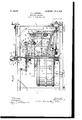
- Figure 1 is a side view, partly in section.
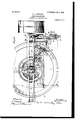
- Fig. 2 is a plan view of the machine.
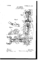
- Fig. 3 is a fragmentary side view, partly in section.
- Figs. 4 and 5 are enlarged detail views of the scoop for collecting the gold which has been separated and left in the machine.
- sand sand, gravel, clay, or disintegrated rock.
- 1 designates a square open frame constructed of channel irons and supported on adjustable screws 2 to provide means for leveling it.
- the tank 2 for receiving the sand is supported centrally within the frame above the ower channel-irons thereof upon brackets 3 and has a bottom 4, whichis conical in form and provided in its inner face at its outer edge with a circular groove 5 for receiving mercury and the gold separated from the sand.
- the pipe 6, which is provided with an annular chamber 6 for containing water,
- the sand is introduced into the tank through a funnel 7
- Water is supplied to the annular chamber by means of a single-acting pump 8, the outlet 9 of the cylinder 10, of which is connected by a pipe 11 with the inlet-pipe 12 by a T 13, and the outlet 14 of the cylinder 15 of which is connected by a pipe 16 with the pipe 11 by a T 17, said pipe 12 also serving as an outlet, and is provided with a stop-cock 17.
- the lower end of the shaft 18 is mounted in a ballbearing hub 19 and has a bevelgear 20 secured thereto below the tank and a hub 21, slidably mounted thereon above the tank by means of a feather on said shaft engaging a slot in the hub 21, and is supported on said shaft by a fixed collar 22.
- an elevator 24 for discharging the sand from the machine, consisting of a casing 25 and a sprocket-chain provided with buckets 26 and running over sprocket-wheels 27 and 28, mounted in the upperand lower ends of said casing.
- the bearing cap-block 29 is mounted on the upper end of the shaft 18, and in this block is mounted a shaft 30, having on one end a disk 31, and on its other end a wormwheel 32, which meshes with a worm 33 on the inner end of a shaft 34, mounted in bearings on top of the frame, the outer end of said shaft being provided with a hand-wheel 35, by which it can be turned.
- the upper ends of the links 36 and 37 are connected to the disk 31 and worm-wheel 32 respectively, by pivot-screws 38, and the lower ends of said links are connected to the ring 39, rotatably mounted in a circular groove 40 in the upper end of the hub by pivot-screws 39 and 39 respectively.
- a miter-gear 42 which meshes with a miter-gear 43, securely mounted on the end of a shaft 44, said shaft being mounted in bearings 47 47 on each of the arms 23, and on this shaft 44 is slidably mounted a gear-wheel 48 by means of a groove therein engaged by the feather 45, said wheel 48 meshing with an annular rack 47, suspended centrally from the top of the frame 1 by brackets 48 the gear-wheel 48 being retained in engagement with the rack 47 by means of arms 49, the outer end provided with a hole, through which the shaft 44 extends, and the inner end having rollers 49, engaginga flange on the interior of the rack 47.
- the rakes 50 are mounted on the frame of the conveyers and travel in the groove in the bottom of the tank for the purpose of stirring up the sand and allowing the gold to drop to the bottom.
- arms 51 depend from the arms 23 and are provided with scrapers 52.
- the power-shaft is mounted in bearings on the lower part of the frame, the inner end having a bevel-gear 61, meshing with the bevel-gear 20 on shaft 18, and the sprocket wheel 62, connected by a sprocket-chain 63 with a sprocket-wheel 64 of the shaft 64 of the disk-wheel 65 of the pump, said disk being connected with the piston-rod 66 of the pistons 67 and 68 by a link 69, one end of which is pivoted to the piston-rod at 70 and the other end pivotally connected to the diskwheel 65 by a pin 71, adjustably engaging an elongated slot 72 therein, whereby the amount pf wiater pumped to the cistern may be reguate
- a scoop 53 which is removably supported on pins 53' on rakes attached to the casing of the elevator and is forced around in the groove in the bottom of the tank.
- the operation is as follows: Power is applied to the shaft 60, and by its connections with the shaft 18 and the shaft 64' of the disk-wheel 64 the pump is started and the hub 21 revolved, carrying the elevator and its attached parts around within the tank and operating said elevators by means of their connection with the stationary rack 47. Sand is then introduced into the tank through the funnel and is forced down the conical bottom into the circular groove 5 by the water flowing through the outlet-holes 7 in the wall of the annular chamber 6 and is thoroughly broken up by the rakes 50, and a the gold is of greater specific gravity than sand it falls to the bottom of said groove and the elevators remove the sand and discharge it from the machine, leaving the pure gold, and this operation goes on until the days work is done.
- the water is then discharged through opening 73, when to remove the gold the scoops are attached to the frame of the elevator and run around in the circular groove 5 and collect the gold. If found necessary, the scrapers 52 may be employed as an additional means for forcing the sand down the conical bottom.
- the sand left in the machine becomes so hard as to cause the elevators to stick therein, they may be raised out of the sand by turning the shaft 34, which has the effect of turning the disk 31 by its connection therewith, and the revolution of said disk raises the links 36 and 37 and the hub 21, to which their lower ends are connected, thereby elevating the elevators carried on the arms 23, secured to said hub. While still in motion, the elevator can be gradually lowered upon the bed of sand and successfully raised.
- a gold-separator the combination of a tank, a circular rack above said tank, a rotatable shaft extending upwardly through said tank, means for operating said shaft, a hub rotatable with and slidable on said shaft, means for sliding said hub on said shaft, arms secured to said hub, elevators rotatably mounted on said arms, laterally-extending shafts for operating said elevators, said shafts rotatably mounted on said arms and having gears on their inner ends and up wardly-extending shafts rotatably mounted on said arms and having gears on their lower ends meshing with the gears on the laterallyextending shafts and gears on their upper ends rotatable therewith and slidable thereon and meshing with said circular rack, substantially as described.
- a tank acircular rack above said tank, apipe projecting up through said tank and having an exterior annular chamber provided with outlet-openings leading into said tank, arotatable shaft extending upwardly through said pipe, means for operating said shaft, ahub rotatable with and slidable on said shaft, means for sliding said hub on said shaft, arms secured to said hub, elevators rotatably mounted on said arms, laterally-extending shafts for operating said elevators, said shafts rotatably mounted on said arms and having gears on their inner ends and upwardly-extending shafts rotatably mounted on said arms and having gears on their lower ends meshing with the gears on the laterally-extending shafts and gears on their upper ends rotatable therewith and slidable thereon and meshing with said circular rack, substantially as described.
- a tank a circular rack above said tank, arotatable shaft extending upwardly through said tank, a hub rotatable with and slidable on said shaft, means for sliding said hub on said shaft, arms secured to said hub, scrapers carried by said arms, elevators rotatablymounted on said arms, laterally-extending shafts for operating said elevators, said shafts rotatablymounted on said arms and having gears on their inner ends and upwardly-extending shafts rotatably mounted on said arms and having gears on their lower ends meshing with the gears on the laterallyextending shafts and gears on their upper ends rotatable therewith and slidable thereon and meshing with said circular rack, substantially as described.
- a rotatable shaft extending upwardly through said tank, means for operating said shaft, ahub rotatable with and slidable on said shaft, a block on the upper end of said shaft, a shaft rotatably mounted on said block and having a worm-wheel on one end and a disk on the other end, links having their upper ends pivoted to said worm-wheel and disk and their lower ends pivoted to said hub, a rotatable shaft having a worm meshing with said wormwheel, arms secured to said hub, elevators rotatably mounted on said arms, laterally-extending shafts for operating said elevators, said shafts rotatably mounted on said arms and having gears on their inner ends and upwardly-extending shafts rotatably mounted on said arms and having gears on their inner ends and upwardly-extending shafts rotatably mounted on said arms and having gears on their lower ends meshing with the gears on the laterally-
- a tank a circular rack above said tank, arotatable shaft extending upwardly through said tank, means for operating said shaft, a hub rotatable with said shaft, arms secured to said hub, elevators rotatably mounted on said arms, laterally-extending shafts for operating said elevators, said shafts rotatably mounted on said arms and having gears on their inner ends and upwardly-extending shafts rotatably mounted on said arms and having gears on their lower ends meshing with the gears on the laterally-extending shafts and gears on their upper ends rotatable therewith and meshing with said circular rack, substantially as described.
- a tank acircular rack above said tank, arotatable shaft extending upwardly through said tank, means for operating said shaft, a hub rotatable with said shaft, arms secured to said hub, scrapers secured to said arms, elevators rotatablymounted on said arms, laterally-extending shafts for operating said elevators, said shafts rotatably mounted on said arms and having gears on their inner ends and upwardly-extending shafts rotatably mounted on said arms and having gears on their lower ends meshing with the gears on the laterally-extending shafts and gears on their upper ends rotatable therewith and meshing with said circular rack, substantially as described.
- a tank a circular rack above said tank, apipe projecting up through said tank and having an exterior annular chamber provided with outlet-openings leading into said tank, arotatable shaft extending upwardly through said pipe, means for operating said shaft, a hub rotatable with said shaft, arms secured to said hub, elevators rotatably mounted on said arms, laterally-extending shafts for operating said elevators, said shafts rotatably mounted on said arms and having gears on their inner ends and upwardlyextending shafts rotatably mounted on said arms and having gears on their lower ends meshing with the gears onthe laterallyextending shafts and gears on their upper ends rotatable therewith and meshing with said circular rack, substantially as described.
Landscapes
- Centrifugal Separators (AREA)
Description
No. 809,586. PATENTED JAN.'9, 1906. B. J. STERLING.
GOLD SEPARATOR.
APPLICATION FILED FEB. 1, 1905.
3 SHEETS-SHEBT l.
wit eases avvuemtoz No. 809,586. PATENTED JAN. 9, 1906.
E. J. STERLING.
GOLD SEPARATOR.
APPLICATION FILED FEB. 1, 19 06.
No. 809,586. PATENTED JAN. 9, 1906. B J STERLING GOLD SEPARATOR. APPLIOATIOW FILED rmm, 1905.
UNITED STATES PATENT OFFICE.
GOLD-SEPARATOR.
Specification of Letters Patent.-
Patented Jan. 9, 1906.
Application filed February 1, 1905. Serial No. 243.609.
To all whom, it may concern:
Be it known that I, EZRA J. STERLING, a citizen of the United States, and a resident of Brooklyn,' in the county of Kings and State of New York, have invented certain new and useful Improvements in Gold-Separators, of which the following is a specification.
My invention relates to gold-separators.
Heretofore by the use of the gold-separating machines generally employed it has been necessary to pass the sand through the machine two or more times in order to separate the gold therefrom.
My invention therefore has for its object the provision of means for obviating this difficulty for providing a machine which by a single passage of the sand therethrough will separate and retain all of the gold, discharge the sand from the machine, and finally collect the gold thus separated.
In the drawings, Figure 1 is a side view, partly in section. Fig. 2 isa plan view of the machine. Fig. 3 is a fragmentary side view, partly in section. Figs. 4 and 5 are enlarged detail views of the scoop for collecting the gold which has been separated and left in the machine.
In this description it will be understood that by the word sand is meant sand, gravel, clay, or disintegrated rock.
Referring to the. drawings illustrating my invention, in which corresponding parts are designated by the same reference characters, 1 designates a square open frame constructed of channel irons and supported on adjustable screws 2 to provide means for leveling it. The tank 2 for receiving the sand is supported centrally within the frame above the ower channel-irons thereof upon brackets 3 and has a bottom 4, whichis conical in form and provided in its inner face at its outer edge with a circular groove 5 for receiving mercury and the gold separated from the sand. The pipe 6, which is provided with an annular chamber 6 for containing water,
projects centrally through the bottom of the tank and is provided with a series of outletholes 7 in its outer wall just above said bottom, throughwhich the waterpasses onto said bottom, separating and forcing the sand and gold down into the circular groove 5, and as the specific gravity of the gold is greater than that of the sand it consequently falls to the bottom of said groove, leaving the sand on top. The sand is introduced into the tank through a funnel 7 Water is supplied to the annular chamber by means of a single-acting pump 8, the outlet 9 of the cylinder 10, of which is connected by a pipe 11 with the inlet-pipe 12 by a T 13, and the outlet 14 of the cylinder 15 of which is connected by a pipe 16 with the pipe 11 by a T 17, said pipe 12 also serving as an outlet, and is provided with a stop-cock 17.
The lower end of the shaft 18 is mounted in a ballbearing hub 19 and has a bevelgear 20 secured thereto below the tank and a hub 21, slidably mounted thereon above the tank by means of a feather on said shaft engaging a slot in the hub 21, and is supported on said shaft by a fixed collar 22.
To the lower end of the hub 21 are secured outwardly-extending arms 23, on the outer end of each of which is mounted an elevator 24 for discharging the sand from the machine, consisting of a casing 25 and a sprocket-chain provided with buckets 26 and running over sprocket- wheels 27 and 28, mounted in the upperand lower ends of said casing.
The bearing cap-block 29 is mounted on the upper end of the shaft 18, and in this block is mounted a shaft 30, having on one end a disk 31, and on its other end a wormwheel 32, which meshes with a worm 33 on the inner end of a shaft 34, mounted in bearings on top of the frame, the outer end of said shaft being provided with a hand-wheel 35, by which it can be turned.
The upper ends of the links 36 and 37 are connected to the disk 31 and worm-wheel 32 respectively, by pivot-screws 38, and the lower ends of said links are connected to the ring 39, rotatably mounted in a circular groove 40 in the upper end of the hub by pivot- screws 39 and 39 respectively.
On the inner end of the shaft 41 of the sprocket-wheel 27 is mounted a miter-gear 42, which meshes with a miter-gear 43, securely mounted on the end of a shaft 44, said shaft being mounted in bearings 47 47 on each of the arms 23, and on this shaft 44 is slidably mounted a gear-wheel 48 by means of a groove therein engaged by the feather 45, said wheel 48 meshing with an annular rack 47, suspended centrally from the top of the frame 1 by brackets 48 the gear-wheel 48 being retained in engagement with the rack 47 by means of arms 49, the outer end provided with a hole, through which the shaft 44 extends, and the inner end having rollers 49, engaginga flange on the interior of the rack 47.
IIO
g The rakes 50 are mounted on the frame of the conveyers and travel in the groove in the bottom of the tank for the purpose of stirring up the sand and allowing the gold to drop to the bottom. For the purpose of forcing the sand from the surface of the conical bottom of the tank, in case this should be necessary, arms 51 depend from the arms 23 and are provided with scrapers 52.
The power-shaft is mounted in bearings on the lower part of the frame, the inner end having a bevel-gear 61, meshing with the bevel-gear 20 on shaft 18, and the sprocket wheel 62, connected by a sprocket-chain 63 with a sprocket-wheel 64 of the shaft 64 of the disk-wheel 65 of the pump, said disk being connected with the piston-rod 66 of the pistons 67 and 68 by a link 69, one end of which is pivoted to the piston-rod at 70 and the other end pivotally connected to the diskwheel 65 by a pin 71, adjustably engaging an elongated slot 72 therein, whereby the amount pf wiater pumped to the cistern may be reguate After the machine is stopped for the day the gold is removed therefrom by means of a scoop 53, which is removably supported on pins 53' on rakes attached to the casing of the elevator and is forced around in the groove in the bottom of the tank.
As each arm 23 is intended to carry the same mechanism, this mechanism has not been shown on each arm, but only on one of the arms.
The operation is as follows: Power is applied to the shaft 60, and by its connections with the shaft 18 and the shaft 64' of the disk-wheel 64 the pump is started and the hub 21 revolved, carrying the elevator and its attached parts around within the tank and operating said elevators by means of their connection with the stationary rack 47. Sand is then introduced into the tank through the funnel and is forced down the conical bottom into the circular groove 5 by the water flowing through the outlet-holes 7 in the wall of the annular chamber 6 and is thoroughly broken up by the rakes 50, and a the gold is of greater specific gravity than sand it falls to the bottom of said groove and the elevators remove the sand and discharge it from the machine, leaving the pure gold, and this operation goes on until the days work is done. The water is then discharged through opening 73, when to remove the gold the scoops are attached to the frame of the elevator and run around in the circular groove 5 and collect the gold. If found necessary, the scrapers 52 may be employed as an additional means for forcing the sand down the conical bottom.
If for any reason the machine is stopped, and as a consequence the sand left in the machine becomes so hard as to cause the elevators to stick therein, they may be raised out of the sand by turning the shaft 34, which has the effect of turning the disk 31 by its connection therewith, and the revolution of said disk raises the links 36 and 37 and the hub 21, to which their lower ends are connected, thereby elevating the elevators carried on the arms 23, secured to said hub. While still in motion, the elevator can be gradually lowered upon the bed of sand and successfully raised.
I do not wish to be understood as limiting myself to the precise details and arrangements of parts shown and described, but reserve the right to all modifications within the scope of my invention.
Having now described my invention, what I claim as new, and desire to secure by Letters Patent, is-
1. In a gold-separator, the combination of a tank, a circular rack above said tank, a rotatable shaft extending upwardly through said tank, means for operating said shaft, a hub rotatable with and slidable on said shaft, means for sliding said hub on said shaft, arms secured to said hub, elevators rotatably mounted on said arms, laterally-extending shafts for operating said elevators, said shafts rotatably mounted on said arms and having gears on their inner ends and up wardly-extending shafts rotatably mounted on said arms and having gears on their lower ends meshing with the gears on the laterallyextending shafts and gears on their upper ends rotatable therewith and slidable thereon and meshing with said circular rack, substantially as described.
2. In a gold-separator, the combination of a tank, acircular rack above said tank, apipe projecting up through said tank and having an exterior annular chamber provided with outlet-openings leading into said tank, arotatable shaft extending upwardly through said pipe, means for operating said shaft, ahub rotatable with and slidable on said shaft, means for sliding said hub on said shaft, arms secured to said hub, elevators rotatably mounted on said arms, laterally-extending shafts for operating said elevators, said shafts rotatably mounted on said arms and having gears on their inner ends and upwardly-extending shafts rotatably mounted on said arms and having gears on their lower ends meshing with the gears on the laterally-extending shafts and gears on their upper ends rotatable therewith and slidable thereon and meshing with said circular rack, substantially as described.
3. In a gold-separator, the combination of a tank, a circular rack above said tank, arotatable shaft extending upwardly through said tank, a hub rotatable with and slidable on said shaft, means for sliding said hub on said shaft, arms secured to said hub, scrapers carried by said arms, elevators rotatablymounted on said arms, laterally-extending shafts for operating said elevators, said shafts rotatablymounted on said arms and having gears on their inner ends and upwardly-extending shafts rotatably mounted on said arms and having gears on their lower ends meshing with the gears on the laterallyextending shafts and gears on their upper ends rotatable therewith and slidable thereon and meshing with said circular rack, substantially as described.
4. In a gold-separator, the combination of a tank, a circular rack above said tank, arotatable shaft extending upwardly through said tank, means for operating said shaft, ahub rotatable with and slidable on said shaft, a block on the upper end of said shaft, a shaft rotatably mounted on said block and having a worm-wheel on one end and a disk on the other end, links having their upper ends pivoted to said worm-wheel and disk and their lower ends pivoted to said hub, a rotatable shaft having a worm meshing with said wormwheel, arms secured to said hub, elevators rotatably mounted on said arms, laterally-extending shafts for operating said elevators, said shafts rotatably mounted on said arms and having gears on their inner ends and upwardly-extending shafts rotatably mounted on said arms and having gears on their inner ends and upwardly-extending shafts rotatably mounted on said arms and having gears on their lower ends meshing with the gears on the laterally-extending shafts and gears on their upper ends rotatable therewith and slidable thereon and meshing with said circular rack, substantially as described.
5. In a gold-separator, the combination of a tank, a circular rack above said tank, arotatable shaft extending upwardly through said tank, means for operating said shaft, a hub rotatable with said shaft, arms secured to said hub, elevators rotatably mounted on said arms, laterally-extending shafts for operating said elevators, said shafts rotatably mounted on said arms and having gears on their inner ends and upwardly-extending shafts rotatably mounted on said arms and having gears on their lower ends meshing with the gears on the laterally-extending shafts and gears on their upper ends rotatable therewith and meshing with said circular rack, substantially as described.
6. In a gold-separator, the combination of a tank, acircular rack above said tank, arotatable shaft extending upwardly through said tank, means for operating said shaft, a hub rotatable with said shaft, arms secured to said hub, scrapers secured to said arms, elevators rotatablymounted on said arms, laterally-extending shafts for operating said elevators, said shafts rotatably mounted on said arms and having gears on their inner ends and upwardly-extending shafts rotatably mounted on said arms and having gears on their lower ends meshing with the gears on the laterally-extending shafts and gears on their upper ends rotatable therewith and meshing with said circular rack, substantially as described.
7. In a gold-separator, the combination of a tank, a circular rack above said tank, apipe projecting up through said tank and having an exterior annular chamber provided with outlet-openings leading into said tank, arotatable shaft extending upwardly through said pipe, means for operating said shaft, a hub rotatable with said shaft, arms secured to said hub, elevators rotatably mounted on said arms, laterally-extending shafts for operating said elevators, said shafts rotatably mounted on said arms and having gears on their inner ends and upwardlyextending shafts rotatably mounted on said arms and having gears on their lower ends meshing with the gears onthe laterallyextending shafts and gears on their upper ends rotatable therewith and meshing with said circular rack, substantially as described.
Signed at New York, in the county of New York and State of New York, this 31st day of January, A. D. 1905.
EZRA J. STERLING.
Witnesses:
MORRIS F. BRAINARD, F. H. BRAINARD.
Priority Applications (1)
| Application Number | Priority Date | Filing Date | Title |
|---|---|---|---|
| US24360905A US809586A (en) | 1905-02-01 | 1905-02-01 | Gold-separator. |
Applications Claiming Priority (1)
| Application Number | Priority Date | Filing Date | Title |
|---|---|---|---|
| US24360905A US809586A (en) | 1905-02-01 | 1905-02-01 | Gold-separator. |
Publications (1)
| Publication Number | Publication Date |
|---|---|
| US809586A true US809586A (en) | 1906-01-09 |
Family
ID=2878067
Family Applications (1)
| Application Number | Title | Priority Date | Filing Date |
|---|---|---|---|
| US24360905A Expired - Lifetime US809586A (en) | 1905-02-01 | 1905-02-01 | Gold-separator. |
Country Status (1)
| Country | Link |
|---|---|
| US (1) | US809586A (en) |
-
1905
- 1905-02-01 US US24360905A patent/US809586A/en not_active Expired - Lifetime
Similar Documents
| Publication | Publication Date | Title |
|---|---|---|
| NO178955B (en) | Rotating filter | |
| US809586A (en) | Gold-separator. | |
| CN114033337A (en) | Formation water discharge equipment for oil exploitation | |
| US1002017A (en) | Vacuum stock thickening and washing machine. | |
| US2751086A (en) | Apparatus for the separation of particles, particularly fibres, that are suspended in a liquid | |
| US1048026A (en) | Ore-separator. | |
| US769156A (en) | Machine for cleansing and separating road-making material. | |
| US483030A (en) | volstorf | |
| US845744A (en) | Machine for cleansing filter-beds. | |
| US2142737A (en) | Sewage screening apparatus | |
| US612706A (en) | Samuel crow | |
| US449552A (en) | Settling and amalgamating pan for machinery for extracting | |
| US796780A (en) | Apparatus for placer-mining. | |
| US840104A (en) | Scraping-machine for closed filters. | |
| US650581A (en) | Amalgamator. | |
| US246237A (en) | And hoeatio | |
| CN222401836U (en) | A new type of centrifuge | |
| US455654A (en) | Territory | |
| US791703A (en) | Centrifugal separator. | |
| US1064296A (en) | Placer-mining machine. | |
| US802725A (en) | Centrifugal ore-separator. | |
| US1315228A (en) | Pujvnograi h co | |
| US1543986A (en) | Centrifugal washing and drying apparatus | |
| US327707A (en) | moffitt | |
| US646532A (en) | Drill gold-dredge. |