US809582A - Machine for peeling vegetables. - Google Patents
Machine for peeling vegetables. Download PDFInfo
- Publication number
- US809582A US809582A US24004705A US1905240047A US809582A US 809582 A US809582 A US 809582A US 24004705 A US24004705 A US 24004705A US 1905240047 A US1905240047 A US 1905240047A US 809582 A US809582 A US 809582A
- Authority
- US
- United States
- Prior art keywords
- vegetables
- disk
- striated
- abrading
- machine
- Prior art date
- Legal status (The legal status is an assumption and is not a legal conclusion. Google has not performed a legal analysis and makes no representation as to the accuracy of the status listed.)
- Expired - Lifetime
Links
- 235000013311 vegetables Nutrition 0.000 title description 23
- 235000002595 Solanum tuberosum Nutrition 0.000 description 14
- 244000061456 Solanum tuberosum Species 0.000 description 14
- 230000000630 rising effect Effects 0.000 description 11
- 235000012015 potatoes Nutrition 0.000 description 10
- 206010040925 Skin striae Diseases 0.000 description 8
- 238000010276 construction Methods 0.000 description 8
- XLYOFNOQVPJJNP-UHFFFAOYSA-N water Substances O XLYOFNOQVPJJNP-UHFFFAOYSA-N 0.000 description 7
- 230000009471 action Effects 0.000 description 6
- 238000005520 cutting process Methods 0.000 description 5
- 238000004519 manufacturing process Methods 0.000 description 5
- 230000006872 improvement Effects 0.000 description 4
- 239000000463 material Substances 0.000 description 4
- 239000002699 waste material Substances 0.000 description 3
- 229910001018 Cast iron Inorganic materials 0.000 description 2
- 230000001154 acute effect Effects 0.000 description 2
- 239000003795 chemical substances by application Substances 0.000 description 2
- 238000000034 method Methods 0.000 description 2
- 208000034656 Contusions Diseases 0.000 description 1
- 238000004140 cleaning Methods 0.000 description 1
- 238000006073 displacement reaction Methods 0.000 description 1
- 229910052571 earthenware Inorganic materials 0.000 description 1
- 239000011521 glass Substances 0.000 description 1
- 238000009499 grossing Methods 0.000 description 1
- 238000007689 inspection Methods 0.000 description 1
- XEEYBQQBJWHFJM-UHFFFAOYSA-N iron Substances [Fe] XEEYBQQBJWHFJM-UHFFFAOYSA-N 0.000 description 1
- 229910052742 iron Inorganic materials 0.000 description 1
- JEIPFZHSYJVQDO-UHFFFAOYSA-N iron(III) oxide Inorganic materials O=[Fe]O[Fe]=O JEIPFZHSYJVQDO-UHFFFAOYSA-N 0.000 description 1
- QJGQUHMNIGDVPM-UHFFFAOYSA-N nitrogen group Chemical group [N] QJGQUHMNIGDVPM-UHFFFAOYSA-N 0.000 description 1
- 239000002245 particle Substances 0.000 description 1
- 229920000136 polysorbate Polymers 0.000 description 1
- 230000008569 process Effects 0.000 description 1
- 230000000284 resting effect Effects 0.000 description 1
- 230000007306 turnover Effects 0.000 description 1
Images
Classifications
-
- A—HUMAN NECESSITIES
- A47—FURNITURE; DOMESTIC ARTICLES OR APPLIANCES; COFFEE MILLS; SPICE MILLS; SUCTION CLEANERS IN GENERAL
- A47J—KITCHEN EQUIPMENT; COFFEE MILLS; SPICE MILLS; APPARATUS FOR MAKING BEVERAGES
- A47J17/00—Household peeling, stringing, or paring implements or machines
- A47J17/14—Machines for peeling
- A47J17/18—Machines for peeling with scraping discs or rotors
Definitions
- This machine has relation to improvements in that type of machines for peeling vegetables wherein an abrading-disk rotates at the bottom of a containing vessel provided with an abrading-lining.
- Machines of this type have been hitherto designed according to two principal plans. In following one plan of construction inelastic sharp cutting edges are provided for acting upon the ma terial to be treated and the turning of individual vegetables is accomplished by special devices introduced in the path of movement of the mass.
- the second plan of construction involves the use of brushes as abrading agents, and the turning of the vegetables to bring all parts successively against the active surfaces is supposed to be acccomplished by the elasticity of the wires or bristles in such brushes. In this form a free path of movement is left for the mass to be treated.
- the invention involves certain improvements capable of advantageous use with any class of active surfaces or abraders, the invention furthermore comprises improvements in-the abraders themselves, whereby the advantages of both of the above classes of construction are united, while avoiding the disadvantages inseparable from each of the older plans.
- the entire device can be easily opened for inspection and cleaning.
- the abraders are divided into sectional elements which are so arranged as to be easily removed and replaced when Worn out, and this whether brushes or other abraders are used.
- the two normally separable parts of the machines are so joined that no water can escape, and this without the use of gaskets or other perishable devices.
- the top of the containing vessel is left entirely open and unobstructed, so that the machine may be charged without any impediment whatever.
- the impelling rotary disk at the bottom of the containing vessel is removable in sections without the use of tools, so as to expose the parts wherein the waste may accumulate, thus facilitating sanitary and convenient operation at all times.
- the improved forms of abraders specifically preferred'and with which one branch of this invention is concerned have the following advantages:
- the vegetables are peeled with a smooth surface instead of being .hackled, and at the same time by avoidance of all sharp cutting edges the minimum of surface material is removed.
- Means are provided for reaching the concave parts of the individual vegetables. These are very common, in many potatoes especially, and are not reached by ordinary means. This feature makes it unnecessary to sort out the properlyshaped potatoes or other ve etables before charging the machine. This feature may be applied to either the brush type or elastic abraders or to the inelastic abraders specifically illustrated herein.
- I/Vhere inelastic abraders are used to line the containing vessel, they are preferably constructed with especial reference to the double movement, tan gential and vertical, imparted to the vegetables by the action of the machine. All danger of broken wires or bristles getting into the potatoes is avoided.
- the abrading, impelling, and turning functions are all united in the rotary disk without any danger of bruising or crushing the vegetables whether small or large, and in the preferred form illustrated herein the utmost efficiency is given to all of these functions.
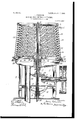
- FIG. 1 is a vertical median section of one form of the device.
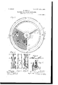
- Fig. 2 is a plan view of the rotary frame for the lower'disk, showing one of the sectional horizontal abraders in place.
- Fi s. 3 and 4 are respectively a front and a bac view of one form of sectional abrader for the pot-lining.
- Fig. 5 is an edge view of the same.
- Fig. 6 is a sectional detail of the joint between the removable pot and the supporting-bowl.
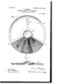
- Fig. 7 is a view similar to Fig. 2, but on a larger scale and showing a modified form of disk abrader.
- Fig. 8 is a view similar to Fig. 2, but on a larger scale and showing a modified form of disk abrader.
- a horizontal frame 12 of circular form covers the bowl 1 and turns on ball-bearin s 13, carried on the hub in said bowl.
- This frame consists of a circular rim 14, having an upwardly-extending flange 15 and joined to the hub 12 by a number of arms 16, preferably three in number and symmetrically placed.
- a circular upturned flange 17 Just over the hub 12 is a circular upturned flange 17, within which stands the lower end of the central spindle 18.
- the hub 12 is firmly keyed to the upper end of the hollow shaft 7, as plainly shown in Fig. 1.
- the spindle 18 is preferably provided with a circular flange 19, as shown in Fig. 1.
- a watersupply pipe 20 brings water from a point beneath the device up through the shaft 7 and the spindle 18 to the sprinkling-ring 21 at the top of the machine.
- An opentopped pot 22, preferably conical, as shown, rests upon the upturned circular edge of the bowl 1, and its inner surface is provided with appropriate abrading means, which may be of any desired construction so far as the general plan of the machine is concerned.
- Appropriate abrading means are supported by the frame 12, and when the vegetables to be peeled are charged upon the disk so formed within the pot 22 said disk is turned by means of the shaft 7, while a stream of water playing through the pipe 20 and sprinkler 21 carries away the detritus into the bowl 1, where it escapes through the wide drain-pipe 23.
- the pot 22 is supplied with a lower base ring 24, which has a wide depending flange or lip 25. (See Fig. 6.)
- This ring has a flat under surface adapted to fit upon the corresponding flat surface of the rim 26 of the bowl 1.
- the pot may be secured in place by any desired meansas, for instance, the locking-pins 27 and butterfly-nuts 28, cooperating with the pairs of lugs 29.
- the water is aided in acting to sweep the detritus toward the center of the bowl. This prevents heaping up of the waste and dirt, which would otherwise tend to obstruct escape of the water to the drain-pipe and tend to force it out of the joint between the bowl and pot.
- the use of the lip or flange 25 inside of the pot at the joint is not broadly claimed herein, as it is covered by the claims of my previously-filed pending application, Serial No. 213,522, filed June 21, 1904.
- a conical casing which may be of sheet-iron, is used, as shown at 30 in Fig. 1.
- the top of this casing fits into a circular channel in the lower part of the upper ring 31, which is removable from said casing.
- the lower edge of the casing is introduced into the deep channel in the top of the lower ring 24 and is preferably soldered in lace to better secure a water-tight oint.
- abrading lining of any desired character is secured within the casing 30 and is held in place, as shown in Fig.
- each of these strips or abradersections is striated or finely ridged tosuch a depth as is sufiicient to accomplish removal of the thin skin of the vegetables to be treated.
- the striae are plainly shown in Fig.
- each bristle or wire acts elastically and whips outa particle of the potato or other vegetable, producing a pitted or hackled appearance. This causes waste of the nourishing part of the potato and unfits the same for table use without subsequent smoothing.
- the disk abraders whether made in the preferred form hereinafter described or otherwise are shaped so as to be accommodated within the spaces between the arms 16 of the disk-frame, and they lie loosely therein, the inner or central edges being held down preferably by means of a ring projecting over said edges.
- the ring is supplied by the flange 19 on the spin dle 18, which acts to prevent the inner edges of all the abraders from being thrown upward, and thus secures them from displacement during use.
- the abraders illustrated are composed of fiat plates 36, having ribs 37 and 38 extending downwardjust within the upward ribs of the arms 16 and the rim.
- the plates 36 fit over these upward ribs of the frame and have in general the shape of the sector of a circle.
- These plates are striated and provided with knobs, as above described, for the pot-linings, save that in the form shown the strioe are substantially radial.
- main striae or ridges extending from the inner to the outer edges of each sector and, in addition to these, secondary strize beginning near the middle of the main strize and extending outward.
- main striae are separated by others over the outer part of each sector, so that successive ridges are not brought too far apart by the radial divergence.
- this rising portion may have any desired surface without departing from the broad invention, I prefer to striate this surface, and in the preferred form shown these striae extend across the rising part at a material angle to the line of movement of the disk.
- the large arrow at the edge of the disk shows the direction of movement of the disk, and it is preferred to arrange the ridges on the rising part, as shown, so that the advancing end of each ridge is nearest the center. This causes the striae to cooperate with the centrifugal force in pushin the vegetables toward the circumference of the vessel.
- each rising part 7 the ridges produce a further turning action around a different axis from that a-r'ound which the vegetables are individually turned by the mere onward movement of each rising part.
- the rounded upper surface of each rising part further acts to enter certain of the concave surfaces, and thus promote rapid completion of the peeling process. It is to be understood that the particular form or arrangement of the rising part as shown is not essential to my invention and that a variety of shapes and a variety of methods of striations will be within the spirit of this invention. I am not limited in these respects in any claim except as expressly stated therein.
- an impelling and abrading member comprising a rotary disk composed of a horizontal fiat striated portion and a raised portion extending from near the circumference inward and having two sides sloping down to the flat striated portion of said disk, substantially as described.
- an impelling and abrading member comprising a rotary disk composed of a number of horizontal flat striated portions separated by raised portions at intervals extending from near the circumference inward, substantially as described.
- an impelling and abrading member comprising a rotary disk composed of a horizontal flat striated portion and a rounded raised portion rising gradually from near the center toward the circumference, substantially as described.
- an impelling and abrading member comprising a rotary disk composed of a horizontal flat striated portion, and a rounded raised portion bounded by two approximately radial edges extending from near the circumference inward and having a striated surface, substantially as described.
- an impelling and abrading member comprising a rotary disk composed of a horizontal flat striated portion and a rounded raised portion bounded by two approximately radial edges extending from near the circumference inward, and having its surface striated at a material an le to the radii of the disk, substantially as described.
- a containing vessel and a removable lining therefor the surface of which is striated and provided with rounded knobs adapted to enter the concavities of potatoes and the like, substantially as described.
- a containing vessel and a removable lining there for composed of vertical sections the surface of each of which is striated and provided with IIO rounded knobs adapted to enter the concavities of potatoes and the like, substantially as described.
- an abrading element for peeling-machines comprising a striated strip having side ribs tapered at their ends, substantially as described.
- an abrading element for peeling-machine's comprising a striated strip having non-parallel sides and tapering ends, and provided with knobs on its striated surface, substantially as described.
- an abrading element for peeling-machines comprising a striated strip with non-parallel sides andhaving ribs along said sides which ribs have tapering ends, substantially as described.
- an abrading element for peeling-machines comprising a concave strip with non-parallel sides and tapering ends, and having striations on its concavesurface making an acute angle with the median line of the strip, substantially as described.
- an abrading element for peeling-machines comprising a flat striated plate conforming roughly in outline to a sector of a circle and having isolated knobs on the working portion of its striated surface, substantially as described.
- a horizontal bowl having an upturned circular edge and a removable pot resting on said edge and having a deep circular lip fitting snugly within HENRY ROBINSON.
Landscapes
- Engineering & Computer Science (AREA)
- Food Science & Technology (AREA)
- Apparatuses For Bulk Treatment Of Fruits And Vegetables And Apparatuses For Preparing Feeds (AREA)
Description
No. 809,582. PATENTED JAN. 9, 1906. H. ROBINSON. MACHINE FOR FEELING VEGETABLES.
APPLICATION FILED JAN. 7, 1905.
3 SHEETSSHEET 1 wi/b'we 0% 20 $3M E E M PATBNTED JAN. 9, 1906.
H. ROBINSON.
MACHINE FOR FEELING VEGETABLES.
APPLICATION FILED JAN. 7, 1905.
3 SHEETS-SHEET Z.
No. 809,582. PATENTED JAN. 9, 1906.
H. ROBINSON. MACHINE FOR FEELING VEGETABLES.
APPLICATION FILED JAN. 7, 1905.
3 SHEETS-SHEET 3;
7) 4 IIIlllllllllllllllllllllllllllllllll m a 61mm,
UNITED STATES HENRY ROBINSON, OF BROOKLYN, NEW YORK.
MACHINE FOR PEELING VEGETABLES.
Specification of Letters Patent.
Patented Jan. 9, 1906.
Application filed January '7, 1905. Serial No. 240,047.
To all whom it may concern.-
Be it known that I, HENRY ROBINSON, a citizen of the United States, residing in the city of Brooklyn, county of Kings, and State of New York, have invented a certain new and useful Improvement in Machines for Peeling Vegetables, of which the following is a specification.
This machine has relation to improvements in that type of machines for peeling vegetables wherein an abrading-disk rotates at the bottom of a containing vessel provided with an abrading-lining. Machines of this type have been hitherto designed according to two principal plans. In following one plan of construction inelastic sharp cutting edges are provided for acting upon the ma terial to be treated and the turning of individual vegetables is accomplished by special devices introduced in the path of movement of the mass. The second plan of construction involves the use of brushes as abrading agents, and the turning of the vegetables to bring all parts successively against the active surfaces is supposed to be acccomplished by the elasticity of the wires or bristles in such brushes. In this form a free path of movement is left for the mass to be treated.
While thepresent invention involves certain improvements capable of advantageous use with any class of active surfaces or abraders, the invention furthermore comprises improvements in-the abraders themselves, whereby the advantages of both of the above classes of construction are united, while avoiding the disadvantages inseparable from each of the older plans.
Among the advantages incident to this invention aside from the nature of the specific abraders used may be mentioned the following: The entire device can be easily opened for inspection and cleaning. The abraders are divided into sectional elements which are so arranged as to be easily removed and replaced when Worn out, and this whether brushes or other abraders are used. The two normally separable parts of the machines are so joined that no water can escape, and this without the use of gaskets or other perishable devices. The top of the containing vessel is left entirely open and unobstructed, so that the machine may be charged without any impediment whatever. The impelling rotary disk at the bottom of the containing vessel is removable in sections without the use of tools, so as to expose the parts wherein the waste may accumulate, thus facilitating sanitary and convenient operation at all times.
The improved forms of abraders specifically preferred'and with which one branch of this invention is concerned have the following advantages: The vegetables are peeled with a smooth surface instead of being .hackled, and at the same time by avoidance of all sharp cutting edges the minimum of surface material is removed. Means are provided for reaching the concave parts of the individual vegetables. These are very common, in many potatoes especially, and are not reached by ordinary means. This feature makes it unnecessary to sort out the properlyshaped potatoes or other ve etables before charging the machine. This feature may be applied to either the brush type or elastic abraders or to the inelastic abraders specifically illustrated herein. I/Vhere inelastic abraders are used to line the containing vessel, they are preferably constructed with especial reference to the double movement, tan gential and vertical, imparted to the vegetables by the action of the machine. All danger of broken wires or bristles getting into the potatoes is avoided. The abrading, impelling, and turning functions are all united in the rotary disk without any danger of bruising or crushing the vegetables whether small or large, and in the preferred form illustrated herein the utmost efficiency is given to all of these functions.
A preferred embodiment of the invention is illustrated in the accompanying drawings, wherein- Figure 1 is a vertical median section of one form of the device. Fig. 2 is a plan view of the rotary frame for the lower'disk, showing one of the sectional horizontal abraders in place. Fi s. 3 and 4 are respectively a front and a bac view of one form of sectional abrader for the pot-lining. Fig. 5 is an edge view of the same. Fig. 6 is a sectional detail of the joint between the removable pot and the supporting-bowl. Fig. 7 is a view similar to Fig. 2, but on a larger scale and showing a modified form of disk abrader. Fig. 8
together by the horizontal flat ring 3, which also serves as a support for the bearing 4 of the driving-shaft 5. In the center of the bowl is a hub 6, which serves as the upper bearing for the upright shaft '7. This shaft is hollow and has its lower bearing 8 at the junction of four strong downwardly-curving braces 9, preferably cast in one piece with the ring 3. This shaft is driven by a bevelwheel 10, which meshes with the pinion 1 1 on the driving-shaft 5. These details of construction are not herein claimed, as they are covered by my prior application for patent, Serial No. 213,522, filed June 21, 1904.
A horizontal frame 12 of circular form covers the bowl 1 and turns on ball-bearin s 13, carried on the hub in said bowl. This frame consists of a circular rim 14, having an upwardly-extending flange 15 and joined to the hub 12 by a number of arms 16, preferably three in number and symmetrically placed. Just over the hub 12 is a circular upturned flange 17, within which stands the lower end of the central spindle 18. The hub 12 is firmly keyed to the upper end of the hollow shaft 7, as plainly shown in Fig. 1. The spindle 18 is preferably provided with a circular flange 19, as shown in Fig. 1. A watersupply pipe 20 brings water from a point beneath the device up through the shaft 7 and the spindle 18 to the sprinkling-ring 21 at the top of the machine. An opentopped pot 22, preferably conical, as shown, rests upon the upturned circular edge of the bowl 1, and its inner surface is provided with appropriate abrading means, which may be of any desired construction so far as the general plan of the machine is concerned. Appropriate abrading means are supported by the frame 12, and when the vegetables to be peeled are charged upon the disk so formed within the pot 22 said disk is turned by means of the shaft 7, while a stream of water playing through the pipe 20 and sprinkler 21 carries away the detritus into the bowl 1, where it escapes through the wide drain-pipe 23.
In the preferred form of this device the pot 22 is supplied with a lower base ring 24, which has a wide depending flange or lip 25. (See Fig. 6.) This ring has a flat under surface adapted to fit upon the corresponding flat surface of the rim 26 of the bowl 1. The pot may be secured in place by any desired meansas, for instance, the locking-pins 27 and butterfly-nuts 28, cooperating with the pairs of lugs 29.
I prefer to give the inner surface of the lip 25 a material slope downward and outward from the center of the bowl in order to give a downward tendency to the stream of water thrown outward from the surface of the rotating disk, which stream impinges against the lip 25. By this expedient reflection of the water back upon the disk is avoided, and the water is aided in acting to sweep the detritus toward the center of the bowl. This prevents heaping up of the waste and dirt, which would otherwise tend to obstruct escape of the water to the drain-pipe and tend to force it out of the joint between the bowl and pot. The use of the lip or flange 25 inside of the pot at the joint is not broadly claimed herein, as it is covered by the claims of my previously-filed pending application, Serial No. 213,522, filed June 21, 1904.
The construction of the pot is preferably as shown in the drawings and as about to be described; but in certain of my claims which do not mention these details I am not to be limited to their use. In this preferred form a conical casing, which may be of sheet-iron, is used, as shown at 30 in Fig. 1. The top of this casing fits into a circular channel in the lower part of the upper ring 31, which is removable from said casing. The lower edge of the casing is introduced into the deep channel in the top of the lower ring 24 and is preferably soldered in lace to better secure a water-tight oint. n abrading lining of any desired character is secured within the casing 30 and is held in place, as shown in Fig. 1, where the top and bottom of the lining are taered to fit the channels in the upper and ower rings 31 and 24. At proper intervals long bolts 32 are passed through the rings be tween the casing and the lining, and nuts 33 are screwed to the lower ends of these bolts to draw the two rings firmly together, and thus tightly secure the casing and its lining. Cavities 33 are provided in the rim 26 of the bowl to accommodate the nuts 32 and allow the flat surfaces of the pot and the bowl to be brought flat together. The lining, whatever its specific construction, is preferably formed of separable sections, so that worn-out parts may be replaced without taking out the whole lining. By securing these sections side by side in themanner above described they need not be accurately proportioned to fit the casing 30, but may be built together firmly in spite of considerable spaces left between them. This is of course impos sible where sections are merely hooped together like barrel-staves.
Those features of the construction thus far described, which are hereinafter-claimed, are disclosed in a prior application for patent, Serial No. 194,108, filed February 17, 1904, of which this is to that extent a continuation and which will be abandoned in favor of this application without prejudice. In said application there were described abraders of the brush type having humps or knobs calculated to enter the concavities in the potatoes or other vegetables to be peeled. These are hereinafter claimed in connection with any type of abrader and are shown in the accompanying drawings at 34. The preferred abraders shown herein are strips such as shown in Figs. 3, 4, and 5,which may be made of a IIO variety of materialssuch as cast-iron, glass, earthenware, &c. When made of cast-iron, they may be galvanized to prevent danger of rust and are molded in the form shown in Figs. 3, 4, and 5. Seen in edge view they are preferably concaved, so as to conform to the inner surface of the casing 30, while the sides are tapered to fit the conical shape of said casing, and ribs 35 lie along said sides, which ribs are tapered at their ends to enter the channels in the securing-rings, as hitherto described and as shown in Fig. 1. The inner face of each of these strips or abradersections is striated or finely ridged tosuch a depth as is sufiicient to accomplish removal of the thin skin of the vegetables to be treated. The striae are plainly shown in Fig. 5, and it is there seen that they offer no chisel or cutting edge, but areformed by sloping faces or sides coming together at substantially the same angle to the general surface of each abrader-section. The edges are dull and are intended for acute rubbing instead of cutting action. This action when exerted upon the skin of a potato, for instance, when it is wet is all that is sufficientv to remove the outer cuticle, while leaving the inner skin, which contains the most nitrogenous part of the potato. In the form of section shown in Figs. 3, 4, and 5 these striae are shown run-. ning vertically from end to end of the surfaces; but my invention is not limited to any specific arrangement thereof. Indeed, the preferred arrangement of the striae is shown in Fig. 9, wherein the direction of movement of the rotary disk, and therefore of the mass to be treated, is supposed to be from right to left. It will be seen that in this figure the stri2e are shown formed at a considerable angle to the length of the abrader-section and so placed that the higher end of each striation is inclined toward the oncoming mass of vegetables. In the operation of the machine a double motion isimparted to the vegetables. The disk imparts a circular motion, to which is added an upward movement against the lining, caused by the pressure of centrifugal force. These components are resolved into an upwardslanting motion substantially at rightangles to the strias as shown in Fig. 9, and thus the arrangement there shown places the ridges substantially directly across or at right angles to the movement of the mass. The upward movement of the potatoes against the abrasive walls is caused by thefact that the centrifugal pressure in the bottom of the mass, where the movement is most rapid, is greater than this pressure at the top of the mass. The consequence of this is that the layer of potatoes at the bottom being prevented from movement horizontally or downward tends to crowd upward, and this tendency is less than that opposed by the potatoes situated nearer the top of the mass. It
is to a greatextent to counteract this tendency, which often when great velocity is employed throws individual potatoes entirely out of the vessel, that the walls of the vessel are made to incline inward toward the top.
It is to be understood that I am not limited to the form of ridges shown in the drawings namely, a V shapebut that my claims cover any fine ridges presenting rubbing edges of a dull or rounded character as opposed to a cutting edge. Furthermore, my invention covers striations of any desired character combined with humps or knobs of such proportions as to conform generally to the average concavities in that class of vegetables intended to be treated. The term knobs as used in my claims is to be thus understood.
One of the main advantages of the striations substantially as herein shown and described lies in the fact that they act to smoothly peel the vegetables, so that they may be presentable without further treatment for table use. Where brushes are used, each bristle or wire acts elastically and whips outa particle of the potato or other vegetable, producing a pitted or hackled appearance. This causes waste of the nourishing part of the potato and unfits the same for table use without subsequent smoothing.
While I have shown a containing vessel lined with abraders, it is to be understood that this is not essential to my broad invention, as the principal abrading agent is really the rotary disk, which also impels the mass forward. The walls of the containing vessel act to continually throw the mass back upon the disk, which acts by centrifugal force to send the mass outward; but the weight of the total mass lying on the impelling-disk, gives to this latter a paramount action on the vegetables.
The disk abraders whether made in the preferred form hereinafter described or otherwise are shaped so as to be accommodated within the spaces between the arms 16 of the disk-frame, and they lie loosely therein, the inner or central edges being held down preferably by means of a ring projecting over said edges. In the specific form shown the ring is supplied by the flange 19 on the spin dle 18, which acts to prevent the inner edges of all the abraders from being thrown upward, and thus secures them from displacement during use.
The abraders illustrated are composed of fiat plates 36, having ribs 37 and 38 extending downwardjust within the upward ribs of the arms 16 and the rim. The plates 36 fit over these upward ribs of the frame and have in general the shape of the sector of a circle. These plates are striated and provided with knobs, as above described, for the pot-linings, save that in the form shown the strioe are substantially radial. As shown in Fig. 2, I
IIQ
prefer to supply main striae or ridges extending from the inner to the outer edges of each sector and, in addition to these, secondary strize beginning near the middle of the main strize and extending outward. By this arrangement the main striae are separated by others over the outer part of each sector, so that successive ridges are not brought too far apart by the radial divergence.
While the sector-shaped elements so far described will answer fairly well in many cases, I prefer the specific form shown in Fi s. 7 and 8, wherein the elements are provided with flat surfaces separated by rising portions extending inward from the circumference toward the center, as shown at 39 in Figs. 7 and 8. This rising portion is preferably bounded by radial sides and is higher at the circumference, sloping toward the center. This is indicated in Fig. 8 by a dotted line which indicates the outer edge of the rising portion which is supposed to be removed by the section plane in the view shown in this figure. While this rising portion may have any desired surface without departing from the broad invention, I prefer to striate this surface, and in the preferred form shown these striae extend across the rising part at a material angle to the line of movement of the disk. The large arrow at the edge of the disk shows the direction of movement of the disk, and it is preferred to arrange the ridges on the rising part, as shown, so that the advancing end of each ridge is nearest the center. This causes the striae to cooperate with the centrifugal force in pushin the vegetables toward the circumference of the vessel.
I have found that where the flat disk is used alone there is a tendency to set up a r0.- tary motion of the mass, wherein each individual soon settles down to a substantially fixed position in the moving mass. This causes undue wear on certain parts of each Vegetable and retards the suflicient action on other parts. The rising parts of each sector shaped abrader act not only to force the mass forward, but inasmuch as the disk as a whole always moves faster than the mass treated these risin parts act to turn over the vegetables next tie bottom, so as to help bring different portions of each separate member of the mass into contact with the different abrading-surfaces. By using striae in the preferred arrangement shown in Fig. 7 the ridges produce a further turning action around a different axis from that a-r'ound which the vegetables are individually turned by the mere onward movement of each rising part. The rounded upper surface of each rising part further acts to enter certain of the concave surfaces, and thus promote rapid completion of the peeling process. It is to be understood that the particular form or arrangement of the rising part as shown is not essential to my invention and that a variety of shapes and a variety of methods of striations will be within the spirit of this invention. I am not limited in these respects in any claim except as expressly stated therein.
While I prefer to use the humps or knobs substantially as shown both in the upright lining and on the rotary disk, it is to be understood that these knobs are not essential to my invention as set forth in certain of my claims wherein the same are not mentioned. Indeed, a variety of changes may be made in various parts of this invention without departing from the spirit thereof, and in each instance the respective claims hereinafter set forth should not be understood to be limited except as expressly therein set forth.
What I claim is 1. In a device of the class described, an impelling and abrading member comprising a rotary disk composed of a horizontal fiat striated portion and a raised portion extending from near the circumference inward and having two sides sloping down to the flat striated portion of said disk, substantially as described.
2. In a device of the class described, an impelling and abrading member comprising a rotary disk composed of a number of horizontal flat striated portions separated by raised portions at intervals extending from near the circumference inward, substantially as described.
3. In a device of the class described, an impelling and abrading member comprising a rotary disk composed of a horizontal flat striated portion and a rounded raised portion rising gradually from near the center toward the circumference, substantially as described.
4. In a device of the class described, an impelling and abrading member comprising a rotary disk composed of a horizontal flat striated portion, and a rounded raised portion bounded by two approximately radial edges extending from near the circumference inward and having a striated surface, substantially as described.
5. In a device of the class described, an impelling and abrading member comprising a rotary disk composed of a horizontal flat striated portion and a rounded raised portion bounded by two approximately radial edges extending from near the circumference inward, and having its surface striated at a material an le to the radii of the disk, substantially as described.
6. In a device of the class described, a containing vessel and a removable lining therefor the surface of which is striated and provided with rounded knobs adapted to enter the concavities of potatoes and the like, substantially as described.
7. In a device of the class described, a containing vessel and a removable lining there for composed of vertical sections the surface of each of which is striated and provided with IIO rounded knobs adapted to enter the concavities of potatoes and the like, substantially as described.
8. As an article of manufacture, an abrading element for peeling-machines comprising a striated strip having side ribs tapered at their ends, substantially as described.
9. As an article of manufacture, an abrading element for peeling-machine's, comprising a striated strip having non-parallel sides and tapering ends, and provided with knobs on its striated surface, substantially as described. v
10. -As an article of manufacture an abrading element for peeling-machines comprising a striated strip with non-parallel sides andhaving ribs along said sides which ribs have tapering ends, substantially as described.
11. As an article of manufacture, an abrading element for peeling-machines, comprising a concave strip with non-parallel sides and tapering ends, and having striations on its concavesurface making an acute angle with the median line of the strip, substantially as described.
12. As an article of manufacture, an abrading element for peeling-machines comprisinga flat striated plate conforming roughly in outline to a sector of a circle and having isolated knobs on the working portion of its striated surface, substantially as described.
13. In a peeling machine, a horizontal bowl having an upturned circular edge and a removable pot resting on said edge and having a deep circular lip fitting snugly within HENRY ROBINSON.
Witnesses H. S. MAGKAYE, FLORENCE S. PEoK.
Priority Applications (1)
| Application Number | Priority Date | Filing Date | Title |
|---|---|---|---|
| US24004705A US809582A (en) | 1905-01-07 | 1905-01-07 | Machine for peeling vegetables. |
Applications Claiming Priority (1)
| Application Number | Priority Date | Filing Date | Title |
|---|---|---|---|
| US24004705A US809582A (en) | 1905-01-07 | 1905-01-07 | Machine for peeling vegetables. |
Publications (1)
| Publication Number | Publication Date |
|---|---|
| US809582A true US809582A (en) | 1906-01-09 |
Family
ID=2878063
Family Applications (1)
| Application Number | Title | Priority Date | Filing Date |
|---|---|---|---|
| US24004705A Expired - Lifetime US809582A (en) | 1905-01-07 | 1905-01-07 | Machine for peeling vegetables. |
Country Status (1)
| Country | Link |
|---|---|
| US (1) | US809582A (en) |
Cited By (6)
| Publication number | Priority date | Publication date | Assignee | Title |
|---|---|---|---|---|
| US2514493A (en) * | 1944-05-18 | 1950-07-11 | Hobart Mfg Co | Machine for peeling and cleaning vegetables and fruits |
| US2626645A (en) * | 1949-10-01 | 1953-01-27 | Adelbert M Hubman | Vegetable peeling apparatus |
| US2795253A (en) * | 1955-04-04 | 1957-06-11 | J D Ferry Co Inc | Vegetable peeling machine |
| US3024821A (en) * | 1957-11-12 | 1962-03-13 | Fmc Corp | Fruit peeling apparatus |
| US5662034A (en) * | 1996-03-08 | 1997-09-02 | Utz Quality Foods, Inc. | Potato peeling system |
| US5752436A (en) * | 1996-10-24 | 1998-05-19 | Utz Quality Foods, Inc. | Potato peeling apparatus |
-
1905
- 1905-01-07 US US24004705A patent/US809582A/en not_active Expired - Lifetime
Cited By (7)
| Publication number | Priority date | Publication date | Assignee | Title |
|---|---|---|---|---|
| US2514493A (en) * | 1944-05-18 | 1950-07-11 | Hobart Mfg Co | Machine for peeling and cleaning vegetables and fruits |
| US2626645A (en) * | 1949-10-01 | 1953-01-27 | Adelbert M Hubman | Vegetable peeling apparatus |
| US2795253A (en) * | 1955-04-04 | 1957-06-11 | J D Ferry Co Inc | Vegetable peeling machine |
| US3024821A (en) * | 1957-11-12 | 1962-03-13 | Fmc Corp | Fruit peeling apparatus |
| US5662034A (en) * | 1996-03-08 | 1997-09-02 | Utz Quality Foods, Inc. | Potato peeling system |
| US5843508A (en) * | 1996-03-08 | 1998-12-01 | Utz Quality Foods, Inc. | Potato peeling system |
| US5752436A (en) * | 1996-10-24 | 1998-05-19 | Utz Quality Foods, Inc. | Potato peeling apparatus |
Similar Documents
| Publication | Publication Date | Title |
|---|---|---|
| US2813376A (en) | Abrading machine actuated by water pressure | |
| US809582A (en) | Machine for peeling vegetables. | |
| US2527695A (en) | Device for comminuting fruits and vegetables | |
| US5307738A (en) | Food processing machine | |
| US2297880A (en) | Fruit and vegetable juicer | |
| US3101107A (en) | Fruit and vegetable juice extractor | |
| US3762308A (en) | Potato peeler | |
| US2345185A (en) | Washing apparatus | |
| JPS6019984B2 (en) | Peeler for vegetables and fruits | |
| US1902506A (en) | Food handling apparatus | |
| US2343327A (en) | Fruit and vegetable juice extractor | |
| US2154650A (en) | Grater | |
| US2387975A (en) | Fruit and vegetable juicer | |
| US942932A (en) | Vegetable-paring machine. | |
| US2879949A (en) | Garbage disposal apparatus | |
| US3496976A (en) | Potato machine,particularly a potato peeling machine | |
| US3677314A (en) | Automatic vegetable peeler | |
| US2286352A (en) | Vegetable peeler | |
| US1066519A (en) | Machine for peeling potatoes and the like. | |
| US1087554A (en) | Vegetable-paring machine. | |
| US1435172A (en) | Dishwashing machine | |
| US555570A (en) | Dish-cleaner | |
| US1701435A (en) | Peeling machine | |
| US2039362A (en) | Dish-supporting rack | |
| US1457007A (en) | Peeling machine |