US809556A - Dial-lock. - Google Patents
Dial-lock. Download PDFInfo
- Publication number
- US809556A US809556A US1904230188A US809556A US 809556 A US809556 A US 809556A US 1904230188 A US1904230188 A US 1904230188A US 809556 A US809556 A US 809556A
- Authority
- US
- United States
- Prior art keywords
- lock
- dial
- plate
- hinge
- lugs
- Prior art date
- Legal status (The legal status is an assumption and is not a legal conclusion. Google has not performed a legal analysis and makes no representation as to the accuracy of the status listed.)
- Expired - Lifetime
Links
- 238000010276 construction Methods 0.000 description 2
- 230000000694 effects Effects 0.000 description 1
- 238000007689 inspection Methods 0.000 description 1
- 238000004519 manufacturing process Methods 0.000 description 1
- 230000002085 persistent effect Effects 0.000 description 1
Images
Classifications
-
- E—FIXED CONSTRUCTIONS
- E05—LOCKS; KEYS; WINDOW OR DOOR FITTINGS; SAFES
- E05B—LOCKS; ACCESSORIES THEREFOR; HANDCUFFS
- E05B37/00—Permutation or combination locks; Puzzle locks
-
- Y—GENERAL TAGGING OF NEW TECHNOLOGICAL DEVELOPMENTS; GENERAL TAGGING OF CROSS-SECTIONAL TECHNOLOGIES SPANNING OVER SEVERAL SECTIONS OF THE IPC; TECHNICAL SUBJECTS COVERED BY FORMER USPC CROSS-REFERENCE ART COLLECTIONS [XRACs] AND DIGESTS
- Y10—TECHNICAL SUBJECTS COVERED BY FORMER USPC
- Y10T—TECHNICAL SUBJECTS COVERED BY FORMER US CLASSIFICATION
- Y10T70/00—Locks
- Y10T70/50—Special application
- Y10T70/5009—For portable articles
- Y10T70/5031—Receptacle
- Y10T70/5035—Bag
- Y10T70/5044—Pivoted rigid jaw
-
- Y—GENERAL TAGGING OF NEW TECHNOLOGICAL DEVELOPMENTS; GENERAL TAGGING OF CROSS-SECTIONAL TECHNOLOGIES SPANNING OVER SEVERAL SECTIONS OF THE IPC; TECHNICAL SUBJECTS COVERED BY FORMER USPC CROSS-REFERENCE ART COLLECTIONS [XRACs] AND DIGESTS
- Y10—TECHNICAL SUBJECTS COVERED BY FORMER USPC
- Y10T—TECHNICAL SUBJECTS COVERED BY FORMER US CLASSIFICATION
- Y10T70/00—Locks
- Y10T70/70—Operating mechanism
- Y10T70/7153—Combination
- Y10T70/7158—Individual blocking elements
-
- Y—GENERAL TAGGING OF NEW TECHNOLOGICAL DEVELOPMENTS; GENERAL TAGGING OF CROSS-SECTIONAL TECHNOLOGIES SPANNING OVER SEVERAL SECTIONS OF THE IPC; TECHNICAL SUBJECTS COVERED BY FORMER USPC CROSS-REFERENCE ART COLLECTIONS [XRACs] AND DIGESTS
- Y10—TECHNICAL SUBJECTS COVERED BY FORMER USPC
- Y10T—TECHNICAL SUBJECTS COVERED BY FORMER US CLASSIFICATION
- Y10T70/00—Locks
- Y10T70/70—Operating mechanism
- Y10T70/7153—Combination
- Y10T70/7181—Tumbler type
- Y10T70/7198—Single tumbler set
- Y10T70/7237—Rotary or swinging tumblers
- Y10T70/726—Individually set
Definitions
- My invention relates to dial-locks, and has for its object the production of a locking device having particular construction and arrangement of the dials, the locking-lugs, and accessory parts designed especially to lock together the meeting and engaging pivotallyconnected portions of the folding-frames usually employed to distend or close the mouths of traveling-bags.
- the unlocking position of the parts is attained by bringing certain characters or marks upon the rotary dials in alinement with each other or with suitablylocated indicating-marks upon the frame.
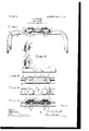
- FIG. 1 represents a side view of the lock closed.
- Fig. 2 is a side view of lock open.
- Fig. 3 is a bottom view with lugs in unlocking position.
- Fig. 4 is a top view with dials in unlocking position.
- Fig. 5 is a side view with the aprons or depending side portions removed to exhibit the particular construction otherwise hidden, and the lock-block and frame members are shown in section.
- FIG. 1 designates the outer and B the inner portion of a bag-mouth frame.
- Fig. 1 a part of the frame B is broken away to show the lock-block C and the lugs D in locking position beneath it.
- Fig. 2 shows that one end only of the dial-supporting plate E is pivoted and that the hinge-plate F of hinge G is secured to the outer and overlapping part of frame A, while hinge-plate H of hinge J is not so attached. (See also Fig. 5.)
- Lugs D project from stems K, which each carry a iixed collar 7c beneath plate F and which pass through the plate and are rigidly and centrally secured to the knurled dialdisks L. Two dials are shown; but others may obviously be introduced, if desired.
- Fig. 3 the keyhole-slots M and N are shown extending through the lock-block C and corresponding 'slots through the overlapping part or iiange of the frame A.
- Fig. 3 the two members or jaw-frames A and B that form the mouth of the bag are closed, and the view is taken from below the lockobstacle.
- dials may be set as the lock is made in such manner that when certain characters upon the dials are toward each other or register with the indicatingmarks Q upon the plate F the lugs D are in positions to pass the'keyhole-slots. Then if the manipulator knows which side of the plate to raise he can effect the unlocking. To one unfamiliar with the circumstances the lock presents an lexceedingly persistent I am aware that hasp-locks possessing dials with stems, lugs, and slotted plates have been constructed, and I do not claim those features broadly.
- a dial-lock the combination with a dial-carrying plate, of rotary dials disposed upon the plate and having stems passing through the plate and provided with lugs, separable elements having slots adapted for the passage of the said stems and lugs whereby said elements are locked together, the said plate having hinge-plates at each end, and one of said hinge-plates being secured to one of said separable elements, and means arranged to cover the edges of both hinge-plates when said dial-carrying plate is in locked position.
- a dial-lock the combination with a dial-carrying plate, of rotary dials disposed upon the plate and having stems passing through the plate and provided with lugs, separable elements having slots adapted for the passage of the said stems and lugs whereby IIO sad'elements are looked together, the said In testimony Whereot ⁇ I affix my signature plate having inwardly-extending hinge-plates in presence of tWo Witnesses. at each end, and one of said hinge-plates be- LOUIS A DRUEHL ing secured to one of sadseparable elements,
Landscapes
- Purses, Travelling Bags, Baskets, Or Suitcases (AREA)
Description
PATBNTED JAN. 9, 1906.
L. A. DRUEHL.
DIAL LOCK.
APPLICATION FILED ocT.27,19o4.
NITEDV STATES PATENT OFFICE.
DIAL-LOCK.
Specification of Letters Patent.
Patented Jan. 9, 1906.
Application filed October 27, 1904. Serial No. 230,188.
To all whom t may concern:
Be it known that I, LOUIs A. DRUEHL, a citizen of the United States, residing at Chicago, in the county of Cook and State of Illinois, have invented certain new and usetul Improvements in Dial-Locks, of which the following is a specification.
My invention relates to dial-locks, and has for its object the production of a locking device having particular construction and arrangement of the dials, the locking-lugs, and accessory parts designed especially to lock together the meeting and engaging pivotallyconnected portions of the folding-frames usually employed to distend or close the mouths of traveling-bags. The unlocking position of the parts is attained by bringing certain characters or marks upon the rotary dials in alinement with each other or with suitablylocated indicating-marks upon the frame.
I accomplish the objects stated by constructing and associating parts, as illustrated in the accompanying drawings, of which- Figure 1 represents a side view of the lock closed. Fig. 2 is a side view of lock open. Fig. 3 is a bottom view with lugs in unlocking position. Fig. 4 is a top view with dials in unlocking position. Fig. 5 is a side view with the aprons or depending side portions removed to exhibit the particular construction otherwise hidden, and the lock-block and frame members are shown in section.
Like letters refer to like parts throughout.
Letter A designates the outer and B the inner portion of a bag-mouth frame. In Fig. 1 a part of the frame B is broken away to show the lock-block C and the lugs D in locking position beneath it. Fig. 2 shows that one end only of the dial-supporting plate E is pivoted and that the hinge-plate F of hinge G is secured to the outer and overlapping part of frame A, while hinge-plate H of hinge J is not so attached. (See also Fig. 5.)
Lugs D project from stems K, which each carry a iixed collar 7c beneath plate F and which pass through the plate and are rigidly and centrally secured to the knurled dialdisks L. Two dials are shown; but others may obviously be introduced, if desired.
In Fig. 3 the keyhole-slots M and N are shown extending through the lock-block C and corresponding 'slots through the overlapping part or iiange of the frame A. In Fig. 3 the two members or jaw-frames A and B that form the mouth of the bag are closed, and the view is taken from below the lockobstacle.
block C, which, as described, is attached to frame B.
In Fig. 5 it will be observed that in addition to slots INI and N through block C and corresponding slots a through frame A recesses f and 7L are formed in hinge-plates F and H, providing for the passage ofthe stems K and lugs -D of the locks.
In operation the user must be acquainted with two circumstances regarding the invention, one being the essential relative positions of the dials-that is to say, he must know the combination and he must also know which end of plate E swings upwardly. He cannot tell either point by external inspection. The dials afford no clue to their predetermined arrangement, and aprons P, extending down on both sides of the lock, hide the hinge-plates F and H, the knuckles and pins ofthe hinges only being exposed. f
It is thought clear that the dials may be set as the lock is made in such manner that when certain characters upon the dials are toward each other or register with the indicatingmarks Q upon the plate F the lugs D are in positions to pass the'keyhole-slots. Then if the manipulator knows which side of the plate to raise he can effect the unlocking. To one unfamiliar with the circumstances the lock presents an lexceedingly persistent I am aware that hasp-locks possessing dials with stems, lugs, and slotted plates have been constructed, and I do not claim those features broadly.
Having described my, invention and its operation, what I claim is- 1. In a dial-lock, the combination with a dial-carrying plate, of rotary dials disposed upon the plate and having stems passing through the plate and provided with lugs, separable elements having slots adapted for the passage of the said stems and lugs whereby said elements are locked together, the said plate having hinge-plates at each end, and one of said hinge-plates being secured to one of said separable elements, and means arranged to cover the edges of both hinge-plates when said dial-carrying plate is in locked position.
2. In a dial-lock, the combination with a dial-carrying plate, of rotary dials disposed upon the plate and having stems passing through the plate and provided with lugs, separable elements having slots adapted for the passage of the said stems and lugs whereby IIO sad'elements are looked together, the said In testimony Whereot` I affix my signature plate having inwardly-extending hinge-plates in presence of tWo Witnesses. at each end, and one of said hinge-plates be- LOUIS A DRUEHL ing secured to one of sadseparable elements,
5 the said dial-carrying plates having aprons Witnesses:
arranged, when said plate is in locked posil ETHEL T. CHASE, tion, to cover the edges of both hinge-plates. l FRANKLIN L. CHASE/
Priority Applications (1)
| Application Number | Priority Date | Filing Date | Title |
|---|---|---|---|
| US1904230188 US809556A (en) | 1904-10-27 | 1904-10-27 | Dial-lock. |
Applications Claiming Priority (1)
| Application Number | Priority Date | Filing Date | Title |
|---|---|---|---|
| US1904230188 US809556A (en) | 1904-10-27 | 1904-10-27 | Dial-lock. |
Publications (1)
| Publication Number | Publication Date |
|---|---|
| US809556A true US809556A (en) | 1906-01-09 |
Family
ID=2878037
Family Applications (1)
| Application Number | Title | Priority Date | Filing Date |
|---|---|---|---|
| US1904230188 Expired - Lifetime US809556A (en) | 1904-10-27 | 1904-10-27 | Dial-lock. |
Country Status (1)
| Country | Link |
|---|---|
| US (1) | US809556A (en) |
Cited By (1)
| Publication number | Priority date | Publication date | Assignee | Title |
|---|---|---|---|---|
| US4669285A (en) * | 1985-11-18 | 1987-06-02 | Kim Guy N | Lock assembly with a changeable locking combination |
-
1904
- 1904-10-27 US US1904230188 patent/US809556A/en not_active Expired - Lifetime
Cited By (1)
| Publication number | Priority date | Publication date | Assignee | Title |
|---|---|---|---|---|
| US4669285A (en) * | 1985-11-18 | 1987-06-02 | Kim Guy N | Lock assembly with a changeable locking combination |
Similar Documents
| Publication | Publication Date | Title |
|---|---|---|
| US685179A (en) | Mail-bag fastener. | |
| US809556A (en) | Dial-lock. | |
| US1336505A (en) | Door-fastener | |
| US633008A (en) | Gate-latch. | |
| US732197A (en) | Device for protecting combination-dials. | |
| US722317A (en) | Traveling-case. | |
| US718878A (en) | Closing and locking device for safes, &c. | |
| US935317A (en) | Bag. | |
| US942753A (en) | Key-fastener. | |
| US745133A (en) | Dress-suit case. | |
| US790110A (en) | Door-wicket. | |
| US510529A (en) | Hinge for folding squares | |
| US410476A (en) | Combined crumb-brush and scraper | |
| US164646A (en) | Improvement in book-clasps | |
| US601241A (en) | Fastening device for hinges | |
| US309152A (en) | moobe | |
| US375684A (en) | Fastening device for mail-bags | |
| US702169A (en) | Dredge-box. | |
| US808189A (en) | Lock for traveling cases. | |
| US437034A (en) | Combination hasp-lock | |
| US970123A (en) | Lock. | |
| US101632A (en) | Improved permutation lock | |
| US738439A (en) | Mail-bag closure. | |
| US971509A (en) | Receptacle-cover. | |
| US1016909A (en) | Placket-fastener. |