US8095138B2 - Resource allocation apparatus, central control apparatus, wireless base station, wireless communication system, resource allocation method and resource allocation program in computer-readable medium - Google Patents
Resource allocation apparatus, central control apparatus, wireless base station, wireless communication system, resource allocation method and resource allocation program in computer-readable medium Download PDFInfo
- Publication number
- US8095138B2 US8095138B2 US11/826,191 US82619107A US8095138B2 US 8095138 B2 US8095138 B2 US 8095138B2 US 82619107 A US82619107 A US 82619107A US 8095138 B2 US8095138 B2 US 8095138B2
- Authority
- US
- United States
- Prior art keywords
- wireless
- channel
- wireless base
- base stations
- base station
- Prior art date
- Legal status (The legal status is an assumption and is not a legal conclusion. Google has not performed a legal analysis and makes no representation as to the accuracy of the status listed.)
- Expired - Fee Related, expires
Links
- 238000004891 communication Methods 0.000 title claims abstract description 108
- 238000013468 resource allocation Methods 0.000 title claims description 80
- 238000000034 method Methods 0.000 title description 132
- 238000005259 measurement Methods 0.000 claims description 13
- 238000004364 calculation method Methods 0.000 claims description 10
- 230000006870 function Effects 0.000 description 29
- 238000010586 diagram Methods 0.000 description 27
- 238000001228 spectrum Methods 0.000 description 14
- 238000007726 management method Methods 0.000 description 6
- 230000015654 memory Effects 0.000 description 4
- 238000004458 analytical method Methods 0.000 description 3
- 230000001174 ascending effect Effects 0.000 description 3
- 230000007423 decrease Effects 0.000 description 2
- 230000002452 interceptive effect Effects 0.000 description 2
- 230000005540 biological transmission Effects 0.000 description 1
- 230000003247 decreasing effect Effects 0.000 description 1
- 238000001514 detection method Methods 0.000 description 1
- 238000009434 installation Methods 0.000 description 1
- 238000012544 monitoring process Methods 0.000 description 1
- 230000003287 optical effect Effects 0.000 description 1
- 238000012545 processing Methods 0.000 description 1
- 238000012887 quadratic function Methods 0.000 description 1
- 230000004044 response Effects 0.000 description 1
- 239000000523 sample Substances 0.000 description 1
- 239000004065 semiconductor Substances 0.000 description 1
- 238000000411 transmission spectrum Methods 0.000 description 1
Images


Classifications
-
- H—ELECTRICITY
- H04—ELECTRIC COMMUNICATION TECHNIQUE
- H04W—WIRELESS COMMUNICATION NETWORKS
- H04W16/00—Network planning, e.g. coverage or traffic planning tools; Network deployment, e.g. resource partitioning or cells structures
- H04W16/02—Resource partitioning among network components, e.g. reuse partitioning
- H04W16/10—Dynamic resource partitioning
-
- H—ELECTRICITY
- H04—ELECTRIC COMMUNICATION TECHNIQUE
- H04W—WIRELESS COMMUNICATION NETWORKS
- H04W16/00—Network planning, e.g. coverage or traffic planning tools; Network deployment, e.g. resource partitioning or cells structures
- H04W16/02—Resource partitioning among network components, e.g. reuse partitioning
- H04W16/04—Traffic adaptive resource partitioning
-
- H—ELECTRICITY
- H04—ELECTRIC COMMUNICATION TECHNIQUE
- H04W—WIRELESS COMMUNICATION NETWORKS
- H04W28/00—Network traffic management; Network resource management
- H04W28/16—Central resource management; Negotiation of resources or communication parameters, e.g. negotiating bandwidth or QoS [Quality of Service]
-
- H—ELECTRICITY
- H04—ELECTRIC COMMUNICATION TECHNIQUE
- H04W—WIRELESS COMMUNICATION NETWORKS
- H04W72/00—Local resource management
- H04W72/50—Allocation or scheduling criteria for wireless resources
- H04W72/54—Allocation or scheduling criteria for wireless resources based on quality criteria
- H04W72/541—Allocation or scheduling criteria for wireless resources based on quality criteria using the level of interference
-
- H—ELECTRICITY
- H04—ELECTRIC COMMUNICATION TECHNIQUE
- H04W—WIRELESS COMMUNICATION NETWORKS
- H04W88/00—Devices specially adapted for wireless communication networks, e.g. terminals, base stations or access point devices
- H04W88/14—Backbone network devices
-
- H—ELECTRICITY
- H04—ELECTRIC COMMUNICATION TECHNIQUE
- H04W—WIRELESS COMMUNICATION NETWORKS
- H04W88/00—Devices specially adapted for wireless communication networks, e.g. terminals, base stations or access point devices
- H04W88/18—Service support devices; Network management devices
-
- H—ELECTRICITY
- H04—ELECTRIC COMMUNICATION TECHNIQUE
- H04W—WIRELESS COMMUNICATION NETWORKS
- H04W92/00—Interfaces specially adapted for wireless communication networks
- H04W92/16—Interfaces between hierarchically similar devices
- H04W92/20—Interfaces between hierarchically similar devices between access points
Definitions
- the present invention pertains to a resource allocation apparatus, a central control apparatus, a wireless base station, a wireless communication system, a resource allocation method and a resource allocation program in a computer-readable medium, for allocating resource information needed to perform wireless communication for a wireless base station including an access-side wireless interface for covering wireless terminal devices and a backbone-side wireless interface for connecting wireless base stations with each other.
- a wireless mesh network is desired to be connected not with cables, but wirelessly for easiness of installation, tolerance for failures or the like.
- non-interfering (non-overlapping) wireless channels in frequency allocation in the 2.4 GHz wireless LAN there is a maximum of only three channels (for example, 1ch, 6ch, and 11ch) within the United States.
- the wireless base stations including a number of wireless network interfaces have a problem of channel interference.
- Japanese Patent No. 3600568 discloses a wireless communication apparatus enabling an empty channel that is not used for communication to be automatically set as a communication channel.
- a technique of document 1 can be applied only to an access-side wireless interface for covering wireless terminal devices.
- non-overlapping wireless channels are allocated, so that the wireless channels cannot be shared, and consequently, communication between the wireless base stations cannot be performed.
- the technique of document 1 cannot be applied to a wireless base station configured to include an access-side wireless interface and a backbone-side wireless interface.
- a technique of document 2 is used to perform channel allocation according to traffic for the backbone-side wireless interface only and does not consider channel allocation associated with the access-side wireless interface.
- a technique of document 3 is that even when each upper node autonomously and distributively sets the wireless channels allocated to a link of the upper node, different wireless channels are prevented from being allocated to the same link by a plurality of upper nodes.
- the technique of document 3 does not consider allocating wireless channels to the access-side wireless interface and the backbone-side wireless interface so that interference between the access-side wireless interface and the backbone-side wireless interface does not occur in the wireless base station including the access-side wireless interface and the backbone-side wireless interface.
- Non-Patent Document 1 discloses a scan scheme of an active scan scheme or a passive scan scheme, or a technique of a spectrum or spectrum mask.
- Information technology Telecommunications and information exchange between systems—Local and metropolitan area networks—Specific requirements Part 11: Wireless LAN Medium Access Control (MAC) and Physical Layer (PHY) specifications (Includes IEEE Std 802.11, 1999 Edition; IEEE Std 802.11a.-1999; IEEE Std 802.11b.-1999; IEEE Std 802.11b.-1999/Cor 1-2001; and IEEE Std 802.11d.-2001 (hereinafter referred to as Non-Patent Document 1)).
- MAC Wireless LAN Medium Access Control
- PHY Physical Layer
- An exemplary feature of the invention is to provide a resource allocation apparatus, a central control apparatus, a wireless base station, a wireless communication system, a resource allocation method and a resource allocation program in a computer-readable medium capable of allocating resource information used in performing wireless communication so as not to generate interference between an access-side wireless interface and a backbone-side wireless interface, used for a wireless base station including the access-side wireless interface for covering wireless terminal devices and the backbone-side wireless interface for connecting wireless base stations with each other.
- a resource allocation apparatus allocates resource information used in performing wireless communication to wireless base stations, wherein each of the wireless base stations includes an access-side wireless interface that covers wireless terminal devices and a backbone-side wireless interface that establishes communication between the wireless base stations, and the resource allocation apparatus includes a resource allocation unit that allocates resource information that is common to the wireless base stations to the backbone-side wireless interface that performs the wireless communication between the wireless base stations, and allocates resource information that does not generate interference with the backbone-side wireless interface to the access-side wireless interface.
- a central control apparatus includes the resource allocation apparatus and a control unit that performs central control on the wireless base stations.
- a wireless base station includes the resource allocation apparatus.
- a wireless communication system includes wireless base stations and a resource allocation apparatus that allocates resource information used in performing wireless communication to the wireless base stations, wherein each of the wireless base stations includes an access-side wireless interface that covers wireless terminal devices and a backbone-side wireless interface that establishes communication between the wireless base stations, and the resource allocation apparatus includes a resource allocation unit that allocates resource information that is common to the wireless base stations to the backbone-side wireless interface that performs the wireless communication between the wireless base stations, and allocates resource information that does not generate interference with the backbone-side wireless interface to the access-side wireless interface.
- a resource allocation method for a resource allocation apparatus that allocates resource information used in performing wireless communication to wireless base stations, wherein each of the wireless base stations includes an access-side wireless interface that covers wireless terminal devices and a backbone-side wireless interface that establishes communication between the wireless base stations, the method including resource allocation processes of allocating resource information that is common to the wireless base stations to the backbone-side wireless interface that performs the wireless communication between the wireless base stations and allocating resource information that does not generate interference with the backbone-side wireless interface to the access-side wireless interface.
- a resource allocation method for a system that includes wireless base stations and a resource allocation apparatus that allocates resource information used in performing wireless communication to the wireless base stations, wherein each of the wireless base stations includes an access-side wireless interface that covers wireless terminal devices and a backbone-side wireless interface that establishes communication between the wireless base stations, the method including resource allocation processes of allocating resource information that is common to the wireless base stations to the backbone-side wireless interface which performs the wireless communication between the wireless base stations and allocating resource information that does not generate interference with the backbone-side wireless interface to the access-side wireless interface.
- a resource allocation program in a computer-readable medium for a resource allocation apparatus which allocates resource information used in performing wireless communication to wireless base stations, wherein each of the wireless base stations includes an access-side wireless interface that covers wireless terminal devices and backbone-side wireless interface that establishes communication between the wireless base stations, the program causing a computer to perform resource allocation processes of allocating resource information that is common to wireless base stations to the backbone-side wireless interface that performs the wireless communication between wireless base stations and allocating resource information that does not generate interference with the backbone-side wireless interface to the access-side wireless interface.
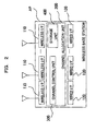
- FIG. 1 is a diagram illustrating a system configuration of a wireless communication system
- FIG. 2 is a diagram illustrating an internal configuration of a wireless base station AP which constitutes the wireless communication system of the present invention
- FIG. 3 is a diagram illustrating an internal configuration of a storage unit 400 of the wireless base station AP which constitutes the wireless communication system of the present invention
- FIG. 4 is a diagram illustrating a system configuration of a public wireless access system configured by connecting a plurality of wireless base stations APs which constitute the wireless communication system of the present invention
- FIG. 5 is a diagram illustrating an example of measurement results in a case where each wireless base station AP performs a channel scan process to measure wireless channel information (received signal strength) on each wireless channel;
- FIG. 6 is a diagram illustrating node information 410 of a storage unit 400 of a leader wireless base station A which constitutes the public wireless access system shown in FIG. 4 , and illustrates a table configuration example in a state where the storage unit 400 of the wireless base station A stores the node information 410 on each wireless base station AP;
- FIG. 7 illustrates an image diagram of topology diagram 450 generated by the leader wireless base station A
- FIG. 8 is a schematic flowchart illustrating a series of processes performed when a wireless channel is determined for the leader wireless base station A;
- FIG. 9 is a flowchart illustrating detailed processes performed when grouping in step S 100 shown in FIG. 8 is performed;
- FIG. 10 is a view illustrating a sort result in a case where the node information 410 shown in FIG. 6 is sorted, in a predetermined order of priority;
- FIG. 11 illustrates an image diagram of topology information 450 in a state where a group 1 is formed
- FIG. 12 is a diagram illustrating node information 410 in a state where the group 1 is formed
- FIG. 13 illustrates an image diagram of topology information 450 in a state after processes of the grouping in the step S 100 of FIG. 8 are performed on the wireless base stations A to D which constitute the public wireless access system shown in FIG. 4 ;
- FIG. 14 is a diagram illustrating node information 410 in a state after the processes of the grouping in the step S 100 of FIG. 8 are performed on the wireless base stations A to D which constitute the public wireless access system shown in FIG. 4 ;
- FIG. 15 is a flowchart illustrating details of a virtual node generating process performed in step S 101 shown in FIG. 8 ;
- FIG. 16 is a diagram illustrating virtual node information 420 when the virtual node generating process in the step S 101 of FIG. 8 is performed on the wireless base stations A to D which constitute the public wireless access system shown in FIG. 4 ;
- FIG. 17 is a diagram illustrating a configuration of virtual nodes in a state after the virtual node generating process in the step S 101 shown in FIG. 8 is performed;
- FIG. 18 is a diagram for explaining a process of determining whether or not there is a virtual node having the number of virtual wireless links of 1;
- FIG. 19 is a flowchart illustrating details of channel allocation to a backbone-side wireless interface 110 in step S 102 shown in FIG. 8 ;
- FIG. 20 is a diagram illustrating a state where wireless channel allocation to the backbone-side wireless interface 110 of the wireless base station AP is completed;
- FIG. 21 is a flowchart illustrating details of channel allocation to an access-side wireless interface 110 of step S 103 shown in FIG. 8 ;
- FIG. 22 is a diagram illustrating a state where wireless channel allocation to the access-side wireless interface 110 of the wireless base station AP is completed;
- FIG. 23 is a diagram illustrating a state where a series of processes shown in FIG. 8 are completed, and a wireless channel is allocated to each wireless base station AP that constitutes the public wireless access system shown in FIG. 4 ;
- FIG. 24 is a diagram illustrating an internal configuration of a wireless base station AP which constitutes a wireless communication system according to a second exemplary embodiment
- FIG. 25 is a diagram illustrating an internal configuration of a storage unit 400 of the wireless base station AP which constitutes the wireless communication system of the present invention
- FIG. 26 is a diagram illustrating a system configuration of a wireless communication system according to a third exemplary embodiment.
- FIG. 27 is a diagram for explaining a received signal strength prediction function f(x).
- the wireless communication system is, as shown in FIG. 1 , a wireless communication system including a plurality of wireless base stations APs.
- a wireless base station AP includes an access-side wireless interface 110 that covers wireless terminal devices STAs, and a backbone-side wireless interface 110 that establishes communication between wireless base stations APs.
- a leader (master) wireless base station AP for managing and controlling each wireless base station AP allocates resource information used in performing wireless communication to each wireless base station AP.
- the leader wireless base station AP allocates resource information that is common to the wireless base stations APs to the backbone-side wireless interfaces 110 that perform wireless communication between the wireless base stations APs, and allocates resource information that does not generate interference with the backbone-side wireless interfaces 110 to the access-side wireless interfaces 110 .
- the leader wireless base station AP allocates resource information used in performing wireless communication so that interference does not occur between the access-side wireless interfaces 110 and the backbone-side wireless interfaces 110 .
- a wireless communication system is a wireless communication system including a plurality of wireless base stations APs and a resource allocation apparatus 1 for allocating resource information used in performing wireless communication to the wireless base stations APs.
- the wireless base station AP includes an access-side wireless interface 110 for covering wireless terminal devices STAs, and a backbone-side wireless interface 110 for connecting wireless base stations AP with each other.
- the resource allocation apparatus 1 allocates resource information that is common to the wireless base stations APs to the backbone-side wireless interfaces 110 which perform wireless communication between the wireless base stations APs and allocates resource information that does not generate interference with the backbone-side wireless interfaces 110 to the access-side wireless interfaces 110 .
- the resource allocation apparatus 1 can allocate the resource information used in performing wireless communication so that interference does not occur between the access-side wireless interfaces 110 and the backbone-side wireless interfaces 110 .
- the wireless communication system includes a plurality of wireless terminal devices STAs and a plurality of wireless base stations APs.
- the wireless base station AP that constitutes the wireless communication system includes a wired interface 120 for connecting with an external network NW and wireless interfaces 110 for connecting with the wireless base stations APs or the wireless terminal devices STAs.
- the wireless interface 110 there are an access-side wireless interface 110 for covering the wireless terminal devices STAs and a backbone-side wireless interface 110 used to access the wireless base stations APs.
- the wireless base station AP includes wireless interfaces 110 , wired interfaces 120 , and a channel allocation unit 200 .
- the wireless interface 110 is an interface for performing wireless communication.
- the wireless base station AP includes one or more wireless interfaces 110 .
- the wireless interface 110 may be applied with wireless interfaces having the same wireless specification (signal strength, directivity, and the like), or wireless interfaces having different wireless specifications.
- the wired interface 120 is an interface for performing wired communication.
- the wireless base station AP that is connected to the external network NW may have the wired interface 120 , while the wireless base station AP that is not connected to the external network NW does not need to have the wired interface 120 .
- the number of the wired interfaces 120 mounted on the wireless base station AP is not specifically limited.
- the channel allocation unit 200 is designed to allocate wireless channels.
- the channel allocation unit 200 includes a channel control unit 300 and a storage unit 400 .
- the channel control unit 300 is designed to allocate a wireless channel proper for the wireless interface 100 on the basis of information stored in the storage unit 400 .
- the storage unit 400 is designed to store information used in allocating a wireless channel to a wireless interface 110 .
- the storage unit 400 stores node information 410 , topology information 450 , and virtual node information 420 .
- the node information 410 is information on the wireless base station AP, and as shown in FIG. 3 , may include the number 411 of available wired interfaces, the total number 412 of wired interfaces, the number 413 of ungrouped wireless interfaces, the total number 414 of wireless interfaces, the number 415 of adjacent wireless base stations, the number 416 of coverable wireless terminal devices, and channel scan information 417 .
- the topology information 460 is information on a connection state of each wireless base station AP.
- the topology information 450 is generated, for example, by exchanging the node information 410 between each wireless base station AP and adjacent wireless base stations APs.
- the virtual node information 420 is information on each group that performs wireless channel allocation.
- the virtual node information 420 may include a configuration node 421 , virtual node channel scan information 422 , and an allocation channel 423 .
- the configuration node 421 is information representing a wireless base station AP that constitutes each virtual node, that is, each group.
- the virtual node channel information 422 is information obtained from channel scan information 417 on the wireless base station AP that constitutes each virtual node, that is, each groups and is information representing a usage state of wireless channels of the group or around the group.
- the virtual node channel scan information 422 may include information representing the usage state of wireless channels around the group.
- the allocation channel 423 is information representing a wireless channel allocated to the virtual node, that is, the group.
- wireless base stations APs shown in FIG. 2 are arbitrarily connected to configure a mesh network.
- wireless terminal devices STAs that exist in a wave coverage range of each wireless base station AP belong to the wireless base station AP to configure the public wireless access system.
- a wireless base station A which constitutes the public wireless access system shown in FIG. 4 connects to an external network NW such as the Internet by using a wired interface 120 .
- the wireless terminal devices STAs that constitute the public wireless access system shown in FIG. 4 connect to the external network NW via the wireless base station A.
- the wireless base station A, a wireless base station B, and a wireless base station C can communicate with one another.
- a wireless base station D can communicate with the wireless base station B.
- wireless terminal devices a, b, and c are covered by the wireless base station A.
- wireless terminal devices d and e are covered by the wireless base station B.
- wireless terminal devices f, g, and h are covered by the wireless base station C.
- each wireless base station AP generates its own node information 410 .
- the number 411 of available wired interfaces is 1 in a case where the wired interface 120 is connected to the external network NW to enable communication, and the number of communicable wired interfaces is stored in the storage unit 400 .
- the wireless base station A Since in the system configuration shown in FIG. 4 , the wireless base station A is connected to the external network NW, the number 411 of available wired interfaces of the wireless base station A is 1.
- the total number 412 of wired interfaces mounted on the wireless base station AP is stored in the storage unit 400 .
- the total number of wired interfaces of the wireless base stations A, B, and D is 1.
- the total number of wired interfaces of the wireless base station C is 2.
- the number 413 of ungrouped wireless interfaces the number of wireless interfaces to which a wireless channel is not allocated (each of which does not belong to a group) is stored in the storage unit 400 .
- the number 413 of ungrouped wireless interfaces is the same as the total number of the wireless interfaces mounted on the wireless base station AP.
- the numbers of ungrouped wireless interfaces of the wireless base stations A and D are 3 in the state of default.
- the number of ungrouped wireless interfaces of the wireless base station B is 4.
- the number of ungrouped wireless interfaces of the wireless base station C is 2.
- the total number 414 of wireless interfaces the total number of the wireless interfaces 110 mounted on the wireless base station AP is stored in the storage unit 400 .
- the numbers of ungrouped wireless interfaces of the wireless base stations A and D are 3.
- the number of ungrouped wireless interfaces of the wireless base station B is 4.
- the number of ungrouped wireless interfaces of the wireless base station C is 2.
- Each wireless base station AP performs a scan process on a wireless state adjacent to itself to acquire the number 415 of adjacent wireless base stations adjacent to the wireless base station AP itself, the number 416 of coverable wireless terminal devices that are covered by the wireless base station AP itself, wireless channel information, and the like, and the acquired information is stored in the storage unit 400 .
- the number of adjacent wireless base stations to the wireless base station A is 2.
- the number of adjacent wireless base stations to the wireless base station B is 3.
- the number of adjacent wireless base stations to the wireless base station C is 2.
- the number of adjacent wireless base stations to the wireless base station D is 1.
- the number of coverable wireless terminal devices of the wireless base station A is 3.
- the number of coverable wireless terminal devices of the wireless base station B is 2.
- the number of coverable wireless terminal devices of the wireless base station C is 3.
- the number of coverable wireless terminal devices of the wireless base station D is 1.
- the channel scan information 417 is used to manage a received signal strength of each wireless channel that is available by the wireless base station AP.
- channel scan information S(x) of a wireless channel x is calculated by using the following Equation 1:
- fs(x) denotes a start frequency in a frequency distribution of the wireless channel x
- fe(x) denotes an end frequency in the frequency distribution of the wireless channel x
- fn(x) denotes the received signal strength prediction function
- N denotes the total number of received signal strengths.
- a function obtained from a diffuse spectrum in the frequency distribution or the like can be applied as the received signal strength prediction function fn(x).
- a function in consideration of a wave attenuation rate or the like can be also applied.
- FIG. 5 illustrates an example of measurement results in a case where the channel scan process is performed to measure wireless channel information (received signal strength) on each wireless channel.
- the measurement results shown in FIG. 5 show that there exists a wireless apparatus that uses a wireless channel 1ch and a received signal strength thereof is 90.
- the wireless channel information (received signal strength) is measured by applying a well-known channel scan scheme.
- the wireless channel information can be measured by applying a scan scheme disclosed in Non-Patent Document 1.
- An active scan scheme or a passive scan scheme is applied.
- the active scan scheme retrieves a network by exchanging a probe request/response frame.
- the passive scan scheme searches through a network by monitoring beacons.
- a dotted line shown in FIG. 6 represents a calculation result of the received signal strength prediction function fn(x) in the aforementioned Equation 1. For example, it is represented that when the wireless channel 1ch is used, the wave interference also occurs to the extent of the wireless channels 2ch and 3ch.
- the received signal strength prediction function fn(x) is calculated based on the received signal strength acquired by applying the aforementioned scan scheme, so that an interference region where wave interference occurs is predicted.
- the channel scan information S(x) of each wireless channel shown in FIG. 5 is calculated by using the received signal strength of each wireless channel and the received signal strength prediction function fn(x) of the aforementioned Equation 1.
- the calculated channel scan information S(x) is stored in the storage unit 400 .
- the channel scan information 417 is measured for each wireless channel, and in a case of the measurement results shown in FIG. 5 , channel scan information 417 from 1ch to 14ch are managed by the storage unit 400 .
- Each wireless base station AP transmits its own node information 410 to the leader (master) wireless base station A.
- the leader wireless base station A acquires the node information 417 on each wireless base station AP, and the wireless base station A stores the node information 410 acquired from each wireless base station AP in the storage unit 400 of the wireless base station A.
- FIG. 6 illustrates a table configuration in a state where the node information 410 on each wireless base station AP is stored in the storage unit 400 of the wireless base station A.
- the node information 410 of each wireless base station AP is managed in a relationship between NUMBER and NAME.
- the NUMBER represents a serial number
- the NAME represents a name of each wireless base station AP.
- a determination method of determining a leader wireless base station AP is not particularly limited, but any determination method may be applied that determines a single wireless base station AP that exists in a network as a leader.
- the leader wireless base station AP may be determined by applying various conditions such as a wireless base station AP having the smallest MAC address of a network interface, or a wireless base station AP connected to the external network NW.
- the node information 410 on each wireless base station AP is managed in a relationship between the NUMBER and the NAME.
- the NUMBER and the NAME are only an example.
- the node information 410 on each wireless base station AP can be identified, the node information 410 on each wireless base station AP can be managed in relation to all of identification information.
- the leader wireless base station A acquires the node information 410 from all the wireless base stations A to D which constitute the public wireless access system (wireless mesh network) and generates the node information 410 shown in FIG. 6 .
- the topology information 450 is generated based on the node information 410 shown in FIG. 6 .
- the wireless base stations APs exchange information with one another and transmit the node information 410 to the leader wireless base station A, so that the leader wireless base station A can acquire the node information 410 of all the wireless base stations A to D which constitute the public wireless access system.
- the leader wireless base station A manages the node information 410 shown in FIG. 6 , and generates the topology information 450 .
- FIG. 7 illustrates an image diagram of the topology information 450 generated by the leader wireless base station A.
- actual nodes connected by solid lines with each other represent wireless base stations that are actually communicating with each other.
- FIG. 7 represents the system configuration of the public wireless access system shown in FIG. 4 , and shows a state where the wireless base stations A, B, and C communicate with one another while the wireless base station D communicates with the wireless base station B.
- n/m denotes a ratio of the number 413 of ungrouped wireless interface(s) of each of the wireless base stations A to D to the total number 414 of wireless interfaces
- n denotes the number 413 of ungrouped wireless interface(s)
- m denotes the total number 414 of wireless interfaces.
- a channel control unit 300 performs grouping on the wireless base stations A to D that constitute the public wireless access system shown in FIG. 4 on the basis of the node information 410 and the topology information 450 stored in the storage unit 400 (step S 100 ).
- FIG. 13 illustrates a state where grouping is performed on the wireless base stations A to D which constitute the public wireless access system shown in FIG. 4 .
- step S 101 a virtual node generating process is performed on the groups of the step S 100 (step S 101 ).
- each group is assumed to be a single virtual node.
- FIG. 7 illustrates a state where the virtual node generating process is performed on each group shown in FIG. 13 .
- the aforementioned process enables channel allocation to be performed to the backbone-side wireless interfaces 110 of each of the wireless base stations A to D that constitute each group (S 102 ).
- FIG. 20 illustrates a state where channel allocation to the backbone-side wireless interface 110 is performed.
- channel allocation to the access-side wireless interfaces 110 is performed on the wireless base stations A to D on which channel allocation to the backbone-side wireless interfaces 110 is performed in the step S 102 so as not to generate interference with the wireless channels allocated to the backbone-side wireless interfaces 110 (S 103 ).
- FIG. 22 illustrates a state where channel allocation to the access-side wireless interfaces 110 is performed.
- step S 104 it is determined whether a feedback process is needed.
- step S 104 the process proceeds to the step S 100 to execute processes of the aforementioned steps S 100 to S 103 .
- step S 104 /No when it is determined that the feedback process is not needed (step S 104 /No), the process is terminated.
- the method of determining whether the feedback process is needed is made as follows. When it is determined that interference between the wireless channel allocated to the backbone-side wireless interface 110 and the wireless channel allocated to the access-side wireless interface 110 occurs, it is determined that the feedback process is needed. When it is determined that interference does not occur, it is determined that the feedback process is not needed.
- Determining whether the feedback process is to be performed makes it possible to perform proper channel allocation to the entire wireless mesh network that constitutes the public wireless access system.
- FIG. 23 illustrates a state where wireless channels are allocated to the backbone-side wireless interfaces 110 and the access-side wireless interfaces 110 included in each of the wireless base stations A to D which constitute the public wireless access system.
- the leader (master) wireless base station A performs a series of processes shown in FIG. 8 , so that for the wireless base stations A to D including the access-side wireless interfaces 110 and the backbone-side wireless interfaces 110 , the leader wireless base station A can allocate a wireless channel that is common to the wireless base stations to the backbone-side wireless interfaces 110 which perform wireless communication between the wireless base stations, and allocate wireless channels which do not generate interference between the access-side wireless interfaces 110 and the backbone-side wireless interfaces 110 to the access-side wireless interfaces 110 .
- the node information 410 on a wireless base station AP of the number of ungrouped wireless I/F> ⁇ is sorted (step S 200 ).
- ⁇ denotes the number of access-side wireless interfaces 100 for covering wireless terminal devices STAs, from among the wireless interfaces 110 mounted on the wireless base station AP and is an integer value that satisfies “0 ⁇ the total number of wireless interfaces included in wireless base station AP”.
- ⁇ is a common fixed value for all the wireless base stations APs, and may be a variable value which is different for each of the wireless base stations APs.
- a wireless base station AP having the large number 411 of available wired interfaces that is, a wireless base station AP connected to the external network NW, has much traffic, and thus, a first priority is provided thereto.
- a wireless base station AP having the small total number 414 of wireless interfaces should be allocated with a small amount of channel resources, so that a second priority is provided thereto.
- a wireless base station AP having the large number 416 of adjacent wireless base stations should be allocated with a large amount of channel resources, so that a third priority is provided thereto.
- a wireless base station AP having the large number 416 of coverable wireless terminal devices needs much traffic, so that a fourth priority is provided thereto.
- the sort order of the node information 410 used to perform the aforementioned grouping is an example, and may be freely changed according to, for example, a configuration of the mesh network or priority information on the wireless base stations APs.
- the wireless base stations AP are sorted in descending order of the numbers 411 of available wired interfaces, or in ascending order of the numbers 414 of wireless interfaces, or in descending order of the numbers 415 of adjacent wireless base stations, or in descending order of the numbers 416 of coverable wireless terminal devices.
- the wireless base stations AP are sorted in descending order of the numbers 411 of available wired interfaces, and the wireless base station A corresponds to NUMBER 1.
- FIG. 10 illustrates a sort result in a case where the node information 410 shown in FIG. 6 is sorted in the aforementioned order of priority.
- a wireless base station AP having the number 413 of ungrouped wireless interface of less than ⁇ is excluded from the sorting target and is excluded from processes described later.
- the wireless base station AP excluded from the sorting target does not exist in the node information 410 shown in FIG. 6 .
- the process proceeds to the step S 200 , and in the second process, the wireless base station C is excluded from the sorting target.
- a range of a wireless base station AP that performs grouping is determined with reference to the topology information 450 (S 201 ).
- the wireless base station AP connected to the external network NW that is, the wireless base station AP having the number 411 of available wired interfaces is provided with a small range of the wireless base station AP that performs the grouping.
- the wireless base station AP having the small total number 414 of wireless interfaces is provided with a small range of the wireless base station AP that performs the grouping.
- the condition of determining the range of the wireless base station AP that performs the grouping is an example, and the condition of determining can be changed so that the range of the wireless base station AP that performs the grouping can be flexibly controlled.
- wireless base stations APs having the number 413 of ungrouped wireless interfaces of a or more are grouped into the same group (S 202 ).
- the grouping information is stored in the storage unit 400 along with the topology information 450 .
- FIG. 11 illustrates an image diagram of the topology information 450 in a state where group 1 is formed.
- FIG. 12 illustrates node information 410 in the state where the group 1 is formed.
- 1 is subtracted from the number 413 of ungrouped wireless interface of the wireless base stations A, B, and C which constitute the group 1 in the states shown in FIGS. 6 and 7 .
- step S 204 it is checked whether group allocation to the wireless interfaces 110 in all of the node information 410 is completed.
- step S 204 it is checked whether group allocation to the wireless interfaces 110 in all of the node information 410 is completed.
- step S 204 /No group allocation to the wireless interfaces 110 in all of the node information 410 is performed.
- step S 204 When it is determined that group allocation to the wireless interfaces 100 in all of the node information 410 is completed (step S 204 /Yes), the process is terminated.
- FIG. 13 illustrates topology information 450 in a state where the grouping process in the step S 100 is completed
- FIG. 14 illustrates node information 410 in a state where the grouping process in the step S 100 is completed.
- a method of allocating sparse wireless channels can be applied to the backbone-side wireless interfaces 110 .
- a single group is selected as a single virtual node, and a junction with another group is stored as a virtual wireless link of another virtual node (S 300 ).
- FIG. 16 illustrates a state where the configuration node 421 is stored in the storage unit 400 .
- channel scan information 417 on all wireless base stations APs that constitute each group is added to calculate virtual node channel scan information 422 , and the calculated virtual node channel scan information 422 is stored in the storage unit 400 (S 301 ).
- the virtual node channel scan information 422 can be obtained by calculating an average value of the channel scan information 417 on all the wireless base stations APs, or performing weighting by use of the topology information 450 or the like and using the channel scan information 417 .
- channel scan information 417 on the actual node A is “10, 44, . . . ”
- channel scan information 417 on the actual node B is “0, 7, . . . ”
- channel scan information 417 on the actual node C is “11, 0, . . . ”.
- each wireless channel (each of the wireless channels 1 to 14 ), and the virtual node channel scan information 422 of the group 1 is calculated.
- the virtual node channel scan information 422 of the group 1 is “7, 17, . . . ”.
- the virtual node channel scan information 422 of the group 2 is “17, 37, . . . ”.
- the virtual node channel scan information 422 of the group 3 is “20, 34, . . . ”.
- step S 302 it is determined whether calculation of the virtual node channel scan information 422 of all groups is completed.
- step S 302 it is determined whether calculation of the virtual node channel scan information 422 of all groups is completed.
- step S 302 when it is determined that calculation of the virtual node channel scan information 422 of all groups is completed (step S 302 /Yes), a next process is performed.
- FIG. 16 illustrates a state where the virtual node channel scan information 422 of all groups are calculated and the obtained values are stored in the storage unit 400 as the virtual node channel scan information 422 .
- step S 303 it is determined whether there is a virtual node having the number of virtual wireless links of 1 (S 303 ).
- a virtual wireless link is set to a virtual node having the smallest number of virtual wireless links from among all virtual nodes that exist within 1 hop from a virtual node connected to the virtual node having the number of virtual wireless links of 1, and is stored as the virtual wireless link (communication failure).
- the virtual nodes connected by the virtual wireless link that is, groups connected by the virtual wireless link (communication failure), can use the same wireless channel when a wireless channel is allocated.
- step S 305 it is determined for all groups whether determination as to whether there is the virtual node having the number of virtual wireless links of 1 is completed.
- step S 305 /No it is determined that determination as to whether or not the virtual node having the number of virtual wireless links of 1 is not completed for all groups.
- step S 305 when it is determined that determination as to whether there is the virtual node having the number of virtual wireless links of 1 is completed for all groups (step S 305 /Yes), the process is terminated.
- FIG. 17 illustrates a configuration of a virtual node in a state where the virtual node generating process is terminated.
- the virtual node having the number of virtual wireless links of 1 does not exist. Therefore, determination as to whether there is the virtual node having the number of virtual wireless links of 1 will be described based on a little complex configuration shown in FIG. 18 .
- a virtual node 8 corresponds to the virtual node having the number of virtual wireless links of 1.
- the numbers of virtual wireless links between the virtual nodes 4 , 5 , and 6 that communicate with the virtual node 7 in one HOP and other virtual nodes, respectively, are 5, 5, and 3.
- the virtual nodes 6 and 8 that have the smallest number of virtual wireless links to other virtual nodes are stored in the storage unit 400 as a virtual wireless link (communication failure).
- virtual nodes are sorted in an order of priority (S 400 ).
- Sorting is performed on the virtual nodes in descending order of the total numbers 412 of wired interfaces of all wireless base stations APs, or in ascending order of the numbers of wireless base stations APs which constitute the virtual nodes.
- a virtual node 1 , a virtual node 2 , and a virtual node 3 are arranged in descending order of the total numbers 412 of the wired interfaces.
- wireless channels are allocated to the virtual nodes that are sorted in the order of priority in the step S 400 (S 401 ).
- the wireless channels are allocated so that the virtual nodes are spaced from each other based on virtual node channel scan information 422 .
- the virtual nodes connected to the virtual wireless link cannot actually communicate with each other, so that wireless channels can be allocated duplicatedly.
- wireless channels are allocated in order of the priority, that is, in order of “virtual node 1 ⁇ virtual node 2 ⁇ virtual node 3 ”.
- a wireless channels having the smallest value of received signal strength from among wireless channels 1ch to 14ch is allocated to the virtual node 1 .
- the virtual node channel scan information 422 selects a wireless channel having the smallest value of received signal strength, and the selected wireless channel is allocated.
- the wireless channel 13ch has the smallest value of received signal strength from among the wireless channels 1ch to 14ch, so that the wireless channel 13ch is allocated.
- the wireless channel 6ch that corresponds to a wireless channel having the smallest value of received signal strength is allocated to the virtual node 1 .
- a wireless channel that has the smallest value of received signal strength and is spaced by 5ch or more from the wireless channel 6ch so as not to generate interference with the wireless channel 6ch allocated to the virtual node 1 is allocated to the virtual node 2 .
- the wireless channel 1ch which is spaced by 5ch or more from the wireless channel 6ch and corresponds to a wireless channel having the smallest value of received signal strength, is allocated.
- a wireless channel which is spaced by 6ch or more from the wireless channels 6ch and 1ch and corresponds to a wireless channel having the smallest value of received signal strength, is allocated to the virtual node 3 .
- the wireless channel ch11 is allocated, which is spaced by 5ch or more from the wireless channels 6ch and 1ch so as not to generate interference with the wireless channel 6ch allocated to the virtual node 1 and the wireless channel 1ch allocated to the virtual node 2 and corresponds to a wireless channel having the smallest value of received signal strength.
- the number of interference occurrences decreases.
- the wireless channel within 5ch is allocated to a virtual node when the number of interference occurrences is low.
- a wireless channel is allocated to each virtual node so that the virtual nodes are spaced from each other.
- a wireless channel that is spaced by 5ch or more is selected in order not to generate interference with the wireless channels allocated to the virtual nodes.
- a value ⁇ between wireless channels for not generating interference is not limited to the 5ch, and may be changed to select a wireless channel spaced by 6ch, 7ch, or the like.
- the value ⁇ between wireless channels is set to be 5ch or more so as not to generate interference in the processes of channel allocation to the virtual nodes. This is because a wireless channel which does not overlap in the 2.5 GHz band is considered (here, 14ch does not interfere 11ch).
- the value ⁇ between wireless channels is set to an arbitrary value so as not to generate interference in consideration of applied frequency band or modulation method, so that wireless channel allocation is performed.
- a wireless channel having the smallest value of received signal strength from among the wireless channels 1ch to 14ch is allocated to each virtual node in order not to generate interference with a wireless channel allocated to a virtual node.
- a configuration is possible that allocates a wireless channel having a smaller value of received signal strength than a predetermined threshold.
- the predetermined threshold may be arbitrarily set and changed.
- received signal strengths of both adjacent wireless channels may be considered, so that an optimal wireless channel from among the plurality of wireless channels may be allocated, or a wireless channel having the smallest value of received signal strength may be allocated.
- step S 402 it is determined for all of the virtual nodes whether wireless channel allocation is completed.
- step S 402 /No it is determined that wireless channel allocation to all the virtual nodes is not completed.
- step S 402 the process is terminated.
- wireless channel allocation to all groups that is, wireless channel allocation to the backbone-side wireless interfaces 110 of the wireless base stations APs.
- FIG. 20 illustrates a state where wireless channel allocation to the backbone-side wireless interface 110 of the wireless base stations APs is completed.
- the wireless channel 6ch is allocated to the group 1
- the wireless channel 1ch is allocated to the group 2
- the wireless channel 11ch is allocated to the group 3 .
- the virtual node channel scan information 422 includes information that represents a usage state of wireless channels around groups. With this configuration, wireless channel allocation is performed so that interference with another system does not occur.
- Channel allocation to the access-side wireless interfaces 110 is performed on wireless interfaces 110 which do not belong to groups.
- a wireless channel is allocated to a wireless interface 110 of a wireless base station AP (S 500 ).
- the wireless channel allocation to an access-side wireless interface 110 of the wireless base station AP is performed in order of “group 1 ⁇ group 2 ⁇ group 3 ”, that is, in the aforementioned order of priority of the sorted virtual nodes.
- the wireless channel allocation to the access-side wireless interfaces 110 of wireless base stations is performed in order of wireless base stations sorted as shown in FIG. 10 , that is, in order of “wireless base station A ⁇ wireless base station C ⁇ wireless base station B”.
- channel allocation to the access-side wireless interface 110 of the wireless base station A is performed.
- the channel allocation to the access-side wireless interface 110 of the wireless base station A is performed as follows.
- the wireless channels 1ch and 6ch are allocated to the backbone-side wireless interface 110 of the wireless base station A by channel allocation to the backbone-side wireless interface 110 in the step S 102 .
- a wireless channel which is spaced from the wireless channels 1ch and 6ch by 5ch or more and has the smallest value of received signal strength is allocated, so that the wireless channel 11ch is allocated to the wireless base station A.
- channel allocation to an access-side wireless interface 110 of the wireless base station C is performed.
- the channel allocation to the access-side wireless interface 110 of the wireless base station C is performed as follows.
- the wireless channel 6ch is allocated to the backbone-side wireless interface 110 of the wireless base station C by the channel allocation to the backbone-side wireless interface 110 in the step S 102 . Consequently, a wireless channel that is spaced by 5ch or more from the wireless channel 6ch and has the smallest value of received signal strength is allocated to the backbone-side wireless interface 110 of the wireless base station C.
- the wireless channel allocation is performed so as not to generate interference with the wireless channel 11ch allocated to the wireless base station A adjacent to the wireless base station C.
- a wireless channel 1ch is allocated to the wireless base station C.
- channel allocation to an access-side wireless interface 110 of the wireless base station B is performed.
- the channel allocation to the access-side wireless interface 110 of the wireless base station B is performed as follows.
- the wireless channels 1ch, 6ch, and 11ch are allocated to the backbone-side wireless interface 110 of the wireless base station B by the channel allocation to the backbone-side wireless interface 110 in the step S 102 . Consequently, a wireless channel that is spaced by 5ch or more from the wireless channels 1ch, 6ch, 11ch and has the smallest value of received signal strength is allocated.
- the wireless channel that is spaced by 5ch or more does not exist. Therefore, a wireless channel which does not generate interference with the wireless channels 1ch, 6ch, and 11ch allocated to the backbone-side wireless interface 110 even if the wireless channel is within 5ch or has influence of interference as less as possible is selected.
- the selected wireless channel is allocated to the wireless channel B.
- the wireless channel is allocated so that the wireless channel does not generate interference with the wireless channels 11ch and 1ch allocated to the wireless base stations A and C adjacent to the wireless base station B.
- the wireless channel 14ch is allocated to the wireless base station B.
- wireless channel allocation to the access-side wireless interfaces of the wireless base stations A, B, and D that belong to the group 2 is performed.
- channel allocation to the access-side wireless interfaces 110 of the wireless base stations A and B Since channel allocation to the access-side wireless interfaces 110 of the wireless base stations A and B is completed, channel allocation to an access-side wireless interface 110 of the wireless base station D is performed.
- the channel allocation to the access-side wireless interface 110 of the wireless base station D is performed as follows.
- the wireless channels 1ch and 11ch are allocated to the backbone-side wireless interface 110 of the wireless base station D by the channel allocation to the backbone-side wireless interface 110 in the step S 102 . Accordingly, a wireless channel, which is spaced by 5ch or more from the wireless channels 1ch and 11ch and has the smallest value of received signal strength, is allocated.
- the wireless channel is allocated so as not to generate interference with a wireless channel 14ch allocated to the wireless base station B adjacent to the wireless base station D.
- step S 501 it is determined whether wireless channel allocation to all wireless base stations APs is completed.
- step S 501 /No it is determined whether wireless channel allocation to all wireless base stations APs is completed.
- step S 501 when it is determined that the wireless channel allocation to all wireless base stations APs is completed (step S 501 /Yes), the process is terminated.
- the wireless channel allocation to the access-side wireless interfaces 110 of the wireless base stations APs is completed.
- FIG. 22 illustrates a state where the wireless channel allocation to the access-side wireless interfaces 110 of the wireless base stations APs.
- the aforementioned channel allocation to the access-side wireless interfaces may employ the method of the channel allocation to the backbone-side wireless interfaces.
- the value ⁇ between wireless channels is set to be an arbitrary value in consideration of the applied frequency band or modulation method so as not to generate interference, so that wireless channel allocation is performed.
- a wireless channel having a smaller value of received signal strength than a predetermined threshold may be allocated.
- the predetermined threshold may be arbitrarily set and changed.
- an optimal wireless channel from among the plurality of wireless channels may be allocated, or a wireless channel having the smallest value of received signal strength may be allocated.
- the feedback process is performed in such a manner that a weighting operation for the channel scan information 417 is changed and the wireless channel allocation is performed again.
- Performing the feedback process in the step S 104 enables to avoid channel interference between the backbone-side wireless interfaces 110 and the access-side wireless interfaces 110 .
- FIG. 23 shows a state where a series of processes shown in FIG. 8 are terminated and a wireless channel is allocated to each of the wireless base stations APs which constitute the public wireless access system.
- the wireless communication system performs the wireless channel allocation to the access-side wireless interfaces 110 for covering wireless terminal devices STAs and to the backbone-side wireless interfaces 110 for connecting the wireless base stations Aps with each other, on the basis of information on the access-side wireless interfaces 110 (for example, information on the number of access-side wireless interfaces, and information on the number of wireless terminal devices covered by the access-side wireless interfaces) and information on the backbone-side wireless interfaces 110 (for example, information on the number of adjacent wireless base stations connected to a wireless base station, and network topology information).
- information on the access-side wireless interfaces 110 for example, information on the number of access-side wireless interfaces, and information on the number of wireless terminal devices covered by the access-side wireless interfaces
- information on the backbone-side wireless interfaces 110 for example, information on the number of adjacent wireless base stations connected to a wireless base station, and network topology information.
- interference may occur between the wireless channels allocated to the backbone-side wireless interfaces 110 and the wireless channels allocated to the access-side wireless interfaces 110 .
- the feedback process is performed, and the channel allocation is performed again.
- the wireless channel allocation is performed so as not to generate interference between the access-side wireless interfaces 110 for covering wireless terminal devices STAs and the backbone-side wireless interfaces 110 for connecting the wireless base stations APs. This enables proper wireless channel allocation to the entire wireless mesh network.
- the wireless communication system groups wireless base stations APs on the basis of information such as the topology information 450 which represents a state of connection between wireless base stations APs, the total number 414 of wireless interfaces, and the number 416 of wireless terminal devices covered by the access-side wireless interfaces 110 .
- the number of wireless base stations APs and a size of the group are appropriately controlled and thus the wireless communication system flexibly copes with various configurations.
- the wireless communication system predicts interference between adjacent channels and calculates the channel scan information 417 for avoiding interference between wireless channels on the basis of the received signal strength acquired in the scan scheme of each wireless base station AP and the received signal strength prediction function fn(x) represented by the aforementioned Equation 1.
- each wireless base station AP includes a position information acquisition unit 500 that acquires its own position information, as shown in FIG. 24 .
- Each wireless base station AP acquires its own position information by using the position information acquisition unit 500 and transmits node information 410 including the position information to a leader wireless base station A.
- the leader wireless base station A acquires position information on each wireless base station AP, so that the leader wireless base station A performs wireless channel allocation in consideration of the position information on each wireless base station AP and therefore performs proper wireless channel allocation so as to reduce the number of interference occurrences.
- a method of acquiring the position information is not limited to a particular method, but may apply all kinds of position information acquisition methods, for example, a global positioning system (GPS).
- GPS global positioning system
- the wireless base station AP that constitutes the wireless communication system includes a position information acquisition unit 500 as shown in FIG. 24 .
- the wireless base station AP according to the second exemplary embodiment has substantially the same functions as the wireless base station AP according to the first exemplary embodiment shown in FIG. 2 except for the above configuration.
- the wireless base station AP allows a storage unit 400 to store the position information acquired by the position information acquisition unit 500 .
- FIG. 25 illustrates a configuration example of the storage unit 400 of the wireless base station AP.
- position information 418 is included in the node information 410 on each wireless base station AP, and the node information 410 including the position information 418 is transmitted to the leader wireless base station A.
- the leader wireless base station A acquires the node information 410 including the position information 418 on each wireless base station AP, and based on the position information 418 on each wireless base station AP that constitutes the wireless base network, can perform wireless channel allocation in consideration of a position where each wireless base station is installed.
- channel allocation that is performed on wireless base stations APs that perform wireless communication and have a narrow wireless wave range, such as wall wireless base stations APs, allows little interference occurrences.
- channel allocation is firstly performed on wireless base stations APs that exist in a region where the wireless base stations APs are locally crowded in order not to generate wave interference, or the channel allocation is performed on wireless base stations disposed at the border to the network in order to allow little interference occurrences. Therefore, channel allocation is performed in consideration of a position where each wireless base station AP is installed.
- the wireless communication system groups the wireless base stations APs and controls the number of wireless base stations APs and a size of the group, on the basis of information such as the topology information 450 that represents a state of connection between wireless base stations APs, the total number 414 of wireless interfaces, the number 416 of wireless terminal devices covered by the access-side wireless interfaces 110 , and the position information 418 on each wireless base station AP.
- the wireless communication system can flexibly cope with various constrictions.
- the wireless communication system includes a plurality of wireless terminal devices STAs and a plurality of wireless base stations APs as shown in FIG. 1 , and determines a leader wireless base station AP from among the plurality of wireless base stations APs.
- each wireless base station AP transmits node information 410 to the leader wireless base station AP, and the leader wireless base station AP performs a series of processes shown in FIG. 8 , so as to perform channel allocation to each wireless base station AP.
- a wireless communication system newly includes a resource allocation apparatus 1 for allocating resource information used for wireless communication to each wireless base station AP.
- the resource allocation apparatus 1 acquires node information 410 on each wireless base station AP and performs a series of processes shown in FIG. 8 performed by the leader wireless base station AP on the basis of the acquired node information 410 , so as to perform channel allocation to each wireless base station AP.
- resource allocation apparatus 1 for allocating resource information to each wireless base station AP is configured, and resource allocation apparatus 1 performs a series of processes shown in FIG. 8 to perform the processes similar to those in the first and second exemplary embodiments.
- Applicable examples of the resource allocation apparatus 1 include a server apparatus for performing the resource allocation process on each wireless base station AP and a central control apparatus for performing central management and control on each wireless base station AP.
- ranges of wireless channels are different from each other depending on wireless methods or countries. For this reason, the ranges or the wireless channels are arbitrarily set and changed according to wireless methods and countries, and the aforementioned processes are performed in the ranges of the wireless channels.
- a wireless channel is allocated to each wireless base station AP.
- information allocated to each wireless base station AP is not limited to the wireless channel, but any information used to perform wireless communication may be allocated to each wireless base station AP as resource information.
- the received signal strength prediction function f(x) is used to calculate channel scan information S(z) on a wireless channel x from Equation 1.
- the received signal strength prediction function f(x) can be used to calculate channel scan information Sm of a wireless channel m from the following Equation 2:
- N denotes the total number of received signal strengths
- Rn denotes a value of received signal strength
- f(x) denotes a received signal strength prediction function
- m denotes a range of a wireless channel
- Cn denotes a wireless channel number.
- the received signal strength prediction function f(x) is, for example, a quadratic function as shown in FIG. 27 .
- Applicable examples of the received signal strength prediction function include a function obtained from a spread spectrum of frequency distribution, etc. and a function in consideration of a wave attenuation rate.
- ranges of wireless channels m are different depending on wireless methods or countries. For example, in IEEE802.11b in U.S., a maximum range M of a wireless channel number is 11.
- the range of the wireless channel m can be arbitrarily set or changed.
- a series of wireless signals received from the wireless base stations APs are used to perform an analysis process that will be described later so as to obtain a power spectrum density P(f), and a function f(x) that uses the obtained power spectrum density P(f) as a peak value becomes the received signal strength prediction function f(x).
- the analysis process can directly perform Fourier transform on the series of wireless signals received from the wireless base stations APs to obtain the power spectrum density P(f).
- Equation 3 a case where a power spectrum density of a certain time waveform x(t) is P(f) means to provide a power Pt for a frequency component of an arbitrary infinitesimal interval (f, f+df), and Equation 3 is obtained:
- a pseudo function f(x) is preferably calculated from a typical spectrum.
- a function f(x) that represents a spectrum or spectrum mask disclosed in Non-Patent Document 1 is preferably used.
- a function f(x) that represents a spectrum disclosed in Non-Patent Document 1 is preferably used.
- Equation 5 is preferably applied as a pseudo function f(x) that represents the aforementioned spectrum.
- Equation 6 is preferably applied as a pseudo function f(x) that represents the aforementioned spectrum mask.
- Control processes of the resource allocation apparatus 1 and the wireless base stations APs which constitute the wireless communication system according to the embodiment(s) may be executed by hardware, software, or a combination thereof.
- a program including a process sequence may be installed in a memory in dedicated hardware in a computer and executed, or installed in a general use computer that executes various processes and executed.
- the program may be stored in a computer-readable medium such as hard disks or read-only memories (ROMs) in advance.
- ROMs read-only memories
- the program may be temporarily or permanently stored in floppy disks, compact disc read-only memories (CD-ROMs), magneto optical (MO) disks, digital versatile discs (DVDs), magnetic disks, and removable recording media such as semiconductor memories.
- CD-ROMs compact disc read-only memories
- MO magneto optical
- DVDs digital versatile discs
- magnetic disks and removable recording media such as semiconductor memories.
- removable recording media may be provided as so-called “package software.”
- the program may be wirelessly transferred to a computer from a download site or through a network such as the Internet.
- the computer may receive the transferred program and install the program in a recording medium such as a hard disk.
- the program may be executed according to the processes described in the exemplary embodiments in time series, or may be in parallel or individually executed according to a processing ability of an apparatus that performs the processes or as needed.
- the wireless communication system may have a logical group configuration of a plurality of apparatuses or may be constructed to combine functions of the apparatuses.
- the exemplary embodiments have the following features.
- each of the wireless base stations may include an access-side wireless interface for covering wireless terminal devices and a backbone-side wireless interface for connecting the wireless base stations with each other, and the resource allocation apparatus may include a resource allocation unit that allocates resource information that is common to the wireless base stations to the backbone-side wireless interface that performs the wireless communication between the wireless base stations, and may allocate resource information that does not generate interference with the backbone-side wireless interface to the access-side wireless interface.
- the resource allocation apparatus may further include a resource management unit that manages resource information allocated to the wireless base stations.
- the resource management unit may manage the resource information according to at least one information of information on the number of wired interfaces of the wireless base station connected to an external network, information on the number of wireless interfaces mounted on the wireless base station, information on the number of connections of the wireless base station to adjacent wireless base stations, information on the number of wireless terminal devices covered by the wireless base station, and information that represents a position of the wireless base station.
- the resource allocation apparatus may further include a grouping unit that groups wireless base stations that perform the wireless communication between wireless base stations, and the resource allocation unit allocates common resource information to the group.
- the grouping unit may group a plurality of wireless base stations, and the resource allocation unit allocates the resource information so as not to generate interference between the plurality of groups.
- the resource allocation apparatus may further include a grouping management unit that manages the number of wireless base stations that are grouped into the groups.
- the grouping management unit may manage the number of the wireless base stations, according to at least one information of information on the number of wired interfaces of the wireless base station connected to an external network in wired, information on the number of wireless interfaces mounted on the wireless base station, information on the number of connections of the wireless base station to adjacent wireless base stations, information on the number of wireless terminal devices covered by the wireless base station, and information that represents a position of the wireless base station.
- a central control apparatus may include the aforementioned resource allocation apparatus and a control unit that performs central control on the wireless base stations.
- a wireless base station may include the aforementioned resource allocation apparatus.
- each of the wireless base stations may include an access-side wireless interface for covering wireless terminal devices and a backbone-side wireless interface for connecting the wireless base stations with each other
- the resource allocation apparatus may include a resource allocation unit that allocates resource information that is common to the wireless base stations to the backbone-side wireless interface that performs the wireless communication between the wireless base stations, and allocates resource information that does not generate interference with the backbone-side wireless interface to the access-side wireless interface.
- the resource information may be a wireless channel
- the wireless base station may include a measurement unit that measures channel information on each wireless channel
- a calculation unit may calculate channel scan information used to avoid interference with respect to each wireless channel on the basis of channel information on each wireless channel measured by the measurement unit
- the resource allocation apparatus may include an acquisition unit that acquires the channel scan information calculated from each wireless channel by the calculation unit from the wireless base station, and the resource allocation unit allocates a wireless channel that is common to wireless base stations to the backbone-side wireless interface that performs wireless communication between wireless base stations and allocates a wireless channel that does not generate interference with the backbone-side wireless interface to the access-side wireless interface on the basis of the channel scan information on each wireless channel acquired by the acquisition unit.
- the wireless base station may include a prediction unit that predicts an interference region of a wireless channel that generates interference on the basis of the channel information on each wireless channel measured by the measurement unit, and the calculation unit may calculate the channel scan information on each wireless channel on the basis of the interference region of the wireless channel predicted by the prediction unit and the channel information on each wireless channel measured by the measurement unit.
- the resource allocation apparatus may be a central control apparatus for performing central control on the wireless base stations.
- the resource allocation apparatus may be the wireless base station.
- each of the wireless base stations may include an access-side wireless interface for covering wireless terminal devices and a backbone-side wireless interface for connecting the wireless base stations with each other, and the resource allocation apparatus may perform resource allocation processes of allocating resource information that is common to the wireless base stations to the backbone-side wireless interface that performs the wireless communication between the wireless base stations and allocating resource information that does not generate interference with the backbone-side wireless interface to the access-side wireless interface.
- the resource allocation apparatus may be a central control apparatus for performing central control on the wireless base stations.
- the resource allocation apparatus may be the wireless base station.
- each of the wireless base stations may include an access-side wireless interface for covering wireless terminal devices and a backbone-side wireless interface for connecting the wireless base stations with each other, and the resource allocation apparatus may perform resource allocation processes of allocating resource information that is common to the wireless base stations to the backbone-side wireless interface that may perform the wireless communication between the wireless base stations and allocating resource information that does not generate interference with the backbone-side wireless interface to the access-side wireless interface.
- the resource allocation apparatus may be a central control apparatus for performing central control on the wireless base stations.
- the resource allocation apparatus may be the wireless base station.
- each of the wireless base stations may include an access-side wireless interface for covering wireless terminal devices and backbone-side wireless interface for connecting the wireless base stations with each other, the program causing a computer to perform resource allocation processes of allocating resource information that is common to wireless base stations to the backbone-side wireless interface that may perform the wireless communication between wireless base stations and allocating resource information that does not generate interference with the backbone-side wireless interface to the access-side wireless interface.
- the resource allocation apparatus may be a central control apparatus for performing central control on the wireless base stations.
- the resource allocation apparatus may be the wireless base station.
- the resource allocation apparatus, the central control apparatus, the wireless base station, the wireless communication system, the resource allocation method and the resource allocation program in a computer-readable medium may be applied to allocate resource information so as to reduce interference, when the wireless base stations APs including a plurality of wireless network interfaces are connected to each other.
- wireless communication apparatuses that have a limited usable frequency band such as mobiles phones, transceivers, and radio controls may be applied in addition to the wireless base stations APs.
Landscapes
- Engineering & Computer Science (AREA)
- Computer Networks & Wireless Communication (AREA)
- Signal Processing (AREA)
- Mobile Radio Communication Systems (AREA)
- Small-Scale Networks (AREA)
Abstract
Description
where, fs(x) denotes a start frequency in a frequency distribution of the wireless channel x; fe(x) denotes an end frequency in the frequency distribution of the wireless channel x; fn(x) denotes the received signal strength prediction function; and N denotes the total number of received signal strengths.
where, N denotes the total number of received signal strengths; Rn denotes a value of received signal strength; f(x) denotes a received signal strength prediction function; m denotes a range of a wireless channel; and Cn denotes a wireless channel number.
where, t2 and t2 denote arbitrary times, and a definition of P(f) is represented by
ƒ(x)=10−5 , x<2
ƒ(x)=10−3, 1<x≦2
ƒ(x)=1, −1≦x≦1
ƒ(x)=10−3, −2≦x<−1
ƒ(x)=10−5 , x<−2 [Equation 6]
Claims (1)
Applications Claiming Priority (6)
| Application Number | Priority Date | Filing Date | Title |
|---|---|---|---|
| JP2006193084 | 2006-07-13 | ||
| JP193084/2006 | 2006-07-13 | ||
| JP2006-193084 | 2006-07-13 | ||
| JP2007-178602 | 2007-07-06 | ||
| JP2007178602A JP5150153B2 (en) | 2006-07-13 | 2007-07-06 | Resource allocation apparatus, centralized control apparatus, radio base station, radio communication system, resource allocation method, and resource allocation program |
| JP178602/2007 | 2007-07-06 |
Publications (2)
| Publication Number | Publication Date |
|---|---|
| US20080014954A1 US20080014954A1 (en) | 2008-01-17 |
| US8095138B2 true US8095138B2 (en) | 2012-01-10 |
Family
ID=38949900
Family Applications (1)
| Application Number | Title | Priority Date | Filing Date |
|---|---|---|---|
| US11/826,191 Expired - Fee Related US8095138B2 (en) | 2006-07-13 | 2007-07-12 | Resource allocation apparatus, central control apparatus, wireless base station, wireless communication system, resource allocation method and resource allocation program in computer-readable medium |
Country Status (2)
| Country | Link |
|---|---|
| US (1) | US8095138B2 (en) |
| JP (1) | JP5150153B2 (en) |
Cited By (1)
| Publication number | Priority date | Publication date | Assignee | Title |
|---|---|---|---|---|
| US20130007232A1 (en) * | 2011-06-28 | 2013-01-03 | Wei Wang | Methods and apparatus to improve security of a virtual private mobile network |
Families Citing this family (14)
| Publication number | Priority date | Publication date | Assignee | Title |
|---|---|---|---|---|
| WO2009084877A1 (en) * | 2007-12-28 | 2009-07-09 | Samsung Electronics Co., Ltd. | Method and apparatus for transmitting/receiving downlink data in wireless communication network |
| KR101465223B1 (en) * | 2008-03-31 | 2014-12-05 | 삼성전자주식회사 | System for ranging based on partitioned radio resource |
| JP5059673B2 (en) * | 2008-03-31 | 2012-10-24 | 株式会社エヌ・ティ・ティ・ドコモ | Mobile communication system and radio resource allocation method |
| JP5581597B2 (en) * | 2009-02-05 | 2014-09-03 | 独立行政法人情報通信研究機構 | Portable communication relay device |
| WO2013042496A1 (en) * | 2011-09-22 | 2013-03-28 | 株式会社日立製作所 | Wireless communication system and wireless communication method and base station device |
| WO2013047952A1 (en) | 2011-09-26 | 2013-04-04 | 엘지전자 주식회사 | Method and apparatus for allocating minimum guaranteed resource amount to access point in wireless access system |
| JP5965866B2 (en) * | 2013-05-09 | 2016-08-10 | 西日本電信電話株式会社 | Relay device, control method, and computer program |
| DE102014204886A1 (en) * | 2014-03-17 | 2015-10-01 | Rohde & Schwarz Gmbh & Co. Kg | Radio transmission system and radio transmission method with multiple channel access |
| JP6558728B2 (en) * | 2014-08-20 | 2019-08-14 | 国立大学法人九州工業大学 | Wireless mesh network system |
| CN107889127B (en) * | 2016-09-30 | 2022-08-16 | 英国电讯有限公司 | Resource management method, device and communication system for cell cluster |
| CN107889116B (en) | 2016-09-30 | 2022-05-10 | 英国电讯有限公司 | Configuration method and device of multi-level cell or cell cluster and communication system |
| CN107889117B (en) | 2016-09-30 | 2022-05-10 | 英国电讯有限公司 | Resource allocation device, resource allocation method and communication system for small cell cluster |
| US10587480B2 (en) * | 2016-11-14 | 2020-03-10 | WiSilica Inc. | User experience enhancement using proximity awareness |
| KR102030128B1 (en) * | 2018-02-28 | 2019-11-08 | 한국과학기술원 | Resource allocating method for wireless backhaul network and apparatus based on machine learning |
Citations (9)
| Publication number | Priority date | Publication date | Assignee | Title |
|---|---|---|---|---|
| US6370384B1 (en) * | 1998-07-30 | 2002-04-09 | Airnet Communications Corporation | Frequency re-use planning for wireless communications system using wireless translating repeaters |
| JP2002345016A (en) | 2001-05-18 | 2002-11-29 | Kddi Research & Development Laboratories Inc | Method and system for assigning radio channel on mesh- like wireless network |
| JP3600568B2 (en) | 2001-09-28 | 2004-12-15 | 株式会社東芝 | Wireless LAN access point |
| US20050152305A1 (en) * | 2002-11-25 | 2005-07-14 | Fujitsu Limited | Apparatus, method, and medium for self-organizing multi-hop wireless access networks |
| US20050208949A1 (en) | 2004-02-12 | 2005-09-22 | Chiueh Tzi-Cker | Centralized channel assignment and routing algorithms for multi-channel wireless mesh networks |
| US20060029028A1 (en) * | 2004-08-04 | 2006-02-09 | Yun-Joo Kim | Apparatus and method for providing frame bridge of wireless local area network |
| US7136655B2 (en) * | 2002-11-21 | 2006-11-14 | Bandspeed, Inc. | Method and apparatus for coverage and throughput enhancement in a wireless communication system |
| US20080090575A1 (en) * | 2006-07-13 | 2008-04-17 | Oz Barak | WiMAX ACCESS POINT NETWORK WITH BACKHAUL TECHNOLOGY |
| US20080165732A1 (en) * | 2001-11-08 | 2008-07-10 | Kim Byoung-Jo J | Frequency assignment for multi-cell IEEE 802.11 wireless networks |
Family Cites Families (3)
| Publication number | Priority date | Publication date | Assignee | Title |
|---|---|---|---|---|
| JP2581438B2 (en) * | 1994-03-18 | 1997-02-12 | 株式会社日立製作所 | Mobile wireless communication method |
| JP2001309419A (en) * | 2000-04-21 | 2001-11-02 | Fujitsu Ltd | Position registration method for mobile communication system, and its mobile unit |
| JP3636695B2 (en) * | 2002-02-22 | 2005-04-06 | エヌ・ティ・ティ・コムウェア株式会社 | Relay terminal device and relay terminal program in wireless communication system |
-
2007
- 2007-07-06 JP JP2007178602A patent/JP5150153B2/en active Active
- 2007-07-12 US US11/826,191 patent/US8095138B2/en not_active Expired - Fee Related
Patent Citations (9)
| Publication number | Priority date | Publication date | Assignee | Title |
|---|---|---|---|---|
| US6370384B1 (en) * | 1998-07-30 | 2002-04-09 | Airnet Communications Corporation | Frequency re-use planning for wireless communications system using wireless translating repeaters |
| JP2002345016A (en) | 2001-05-18 | 2002-11-29 | Kddi Research & Development Laboratories Inc | Method and system for assigning radio channel on mesh- like wireless network |
| JP3600568B2 (en) | 2001-09-28 | 2004-12-15 | 株式会社東芝 | Wireless LAN access point |
| US20080165732A1 (en) * | 2001-11-08 | 2008-07-10 | Kim Byoung-Jo J | Frequency assignment for multi-cell IEEE 802.11 wireless networks |
| US7136655B2 (en) * | 2002-11-21 | 2006-11-14 | Bandspeed, Inc. | Method and apparatus for coverage and throughput enhancement in a wireless communication system |
| US20050152305A1 (en) * | 2002-11-25 | 2005-07-14 | Fujitsu Limited | Apparatus, method, and medium for self-organizing multi-hop wireless access networks |
| US20050208949A1 (en) | 2004-02-12 | 2005-09-22 | Chiueh Tzi-Cker | Centralized channel assignment and routing algorithms for multi-channel wireless mesh networks |
| US20060029028A1 (en) * | 2004-08-04 | 2006-02-09 | Yun-Joo Kim | Apparatus and method for providing frame bridge of wireless local area network |
| US20080090575A1 (en) * | 2006-07-13 | 2008-04-17 | Oz Barak | WiMAX ACCESS POINT NETWORK WITH BACKHAUL TECHNOLOGY |
Non-Patent Citations (2)
| Title |
|---|
| ISO/IEC 8802-11, "IEEE Standard for InformationTechnology-Telecommunications and information exchange between systems-Local and metropolitan area networks-Specific requirements: Part 11: Wireless LAN Medium Access Control (MAC) and Physical (PHY) Specifications", ANSI/IEEE Std 802.11, 1999 Edition, pp. 1-7. |
| ISO/IEC 8802-11, "IEEE Standard for InformationTechnology—Telecommunications and information exchange between systems—Local and metropolitan area networks—Specific requirements: Part 11: Wireless LAN Medium Access Control (MAC) and Physical (PHY) Specifications", ANSI/IEEE Std 802.11, 1999 Edition, pp. 1-7. |
Cited By (3)
| Publication number | Priority date | Publication date | Assignee | Title |
|---|---|---|---|---|
| US20130007232A1 (en) * | 2011-06-28 | 2013-01-03 | Wei Wang | Methods and apparatus to improve security of a virtual private mobile network |
| US9172678B2 (en) * | 2011-06-28 | 2015-10-27 | At&T Intellectual Property I, L.P. | Methods and apparatus to improve security of a virtual private mobile network |
| US9537829B2 (en) | 2011-06-28 | 2017-01-03 | At&T Intellectual Property I, L.P. | Methods and apparatus to improve security of a virtual private mobile network |
Also Published As
| Publication number | Publication date |
|---|---|
| US20080014954A1 (en) | 2008-01-17 |
| JP2008042897A (en) | 2008-02-21 |
| JP5150153B2 (en) | 2013-02-20 |
Similar Documents
| Publication | Publication Date | Title |
|---|---|---|
| US8095138B2 (en) | Resource allocation apparatus, central control apparatus, wireless base station, wireless communication system, resource allocation method and resource allocation program in computer-readable medium | |
| US8000714B2 (en) | Interference prediction apparatus, interference prediction method, and interference prediction program in computer-readable medium | |
| EP2392167B1 (en) | Dynamic frequency selection in a cognitive radio system, | |
| US9794774B2 (en) | Method and apparatus for cognitive radio coexistence | |
| JP5104769B2 (en) | Communications system | |
| USRE45302E1 (en) | System and method for reuse of communication spectrum for fixed and mobile applications with efficient method to mitigate interference | |
| US10004075B2 (en) | Communication control apparatus, communication control method, and communication system | |
| EP2542015B1 (en) | Wireless communication system, coexistence manager installed in said system, and method for wireless communication | |
| US20180213407A1 (en) | Spectrum sharing method and device | |
| JP2017085594A (en) | Method and apparatus for opportunistic radio resource allocation in multi-carrier communication system | |
| US11863996B2 (en) | Centralized coordination for shared spectrum systems | |
| JP2007533224A (en) | Dynamic allocation of radio resources | |
| WO2018140291A1 (en) | Predicting future spectrum utilization | |
| EP4029304A1 (en) | Quality of service (qos) based wireless coverage map | |
| EP3398367A1 (en) | Network performance framework for wireless local area networks | |
| WO2020105191A1 (en) | Communication device and wireless communication system | |
| US20200162930A1 (en) | Method for dynamic selection of communication resources in a heterogeneous type cellular network | |
| KR101340830B1 (en) | Channel localization method for solving ripple effect problem in small-sized wifi networks and apparatus thereof | |
| Hneiti et al. | Dependability analysis of wireless local area networks | |
| EP3226602A1 (en) | Telecommunications network | |
| WO2018121958A1 (en) | Prioritized access to shared spectrum based on dynamic mac profile selection |
Legal Events
| Date | Code | Title | Description |
|---|---|---|---|
| AS | Assignment |
Owner name: NEC COMMUNICATION SYSTEMS, LTD., JAPAN Free format text: ASSIGNMENT OF ASSIGNORS INTEREST;ASSIGNORS:MATSUMOTO, AKIRA;ITO, TETSUYA;IIZUKA, HIROYUKI;AND OTHERS;REEL/FRAME:019913/0351 Effective date: 20070718 |
|
| ZAAA | Notice of allowance and fees due |
Free format text: ORIGINAL CODE: NOA |
|
| ZAAB | Notice of allowance mailed |
Free format text: ORIGINAL CODE: MN/=. |
|
| STCF | Information on status: patent grant |
Free format text: PATENTED CASE |
|
| FPAY | Fee payment |
Year of fee payment: 4 |
|
| MAFP | Maintenance fee payment |
Free format text: PAYMENT OF MAINTENANCE FEE, 8TH YEAR, LARGE ENTITY (ORIGINAL EVENT CODE: M1552); ENTITY STATUS OF PATENT OWNER: LARGE ENTITY Year of fee payment: 8 |
|
| FEPP | Fee payment procedure |
Free format text: MAINTENANCE FEE REMINDER MAILED (ORIGINAL EVENT CODE: REM.); ENTITY STATUS OF PATENT OWNER: LARGE ENTITY |
|
| LAPS | Lapse for failure to pay maintenance fees |
Free format text: PATENT EXPIRED FOR FAILURE TO PAY MAINTENANCE FEES (ORIGINAL EVENT CODE: EXP.); ENTITY STATUS OF PATENT OWNER: LARGE ENTITY |
|
| STCH | Information on status: patent discontinuation |
Free format text: PATENT EXPIRED DUE TO NONPAYMENT OF MAINTENANCE FEES UNDER 37 CFR 1.362 |
|
| FP | Lapsed due to failure to pay maintenance fee |
Effective date: 20240110 |