US8095023B2 - Image forming apparatus - Google Patents
Image forming apparatus Download PDFInfo
- Publication number
- US8095023B2 US8095023B2 US12/021,596 US2159608A US8095023B2 US 8095023 B2 US8095023 B2 US 8095023B2 US 2159608 A US2159608 A US 2159608A US 8095023 B2 US8095023 B2 US 8095023B2
- Authority
- US
- United States
- Prior art keywords
- unit
- temperature sensing
- sensing unit
- heating roller
- temperature
- Prior art date
- Legal status (The legal status is an assumption and is not a legal conclusion. Google has not performed a legal analysis and makes no representation as to the accuracy of the status listed.)
- Expired - Fee Related, expires
Links
Images


Classifications
-
- G—PHYSICS
- G03—PHOTOGRAPHY; CINEMATOGRAPHY; ANALOGOUS TECHNIQUES USING WAVES OTHER THAN OPTICAL WAVES; ELECTROGRAPHY; HOLOGRAPHY
- G03G—ELECTROGRAPHY; ELECTROPHOTOGRAPHY; MAGNETOGRAPHY
- G03G15/00—Apparatus for electrographic processes using a charge pattern
- G03G15/20—Apparatus for electrographic processes using a charge pattern for fixing, e.g. by using heat
- G03G15/2003—Apparatus for electrographic processes using a charge pattern for fixing, e.g. by using heat using heat
- G03G15/2014—Apparatus for electrographic processes using a charge pattern for fixing, e.g. by using heat using heat using contact heat
- G03G15/2039—Apparatus for electrographic processes using a charge pattern for fixing, e.g. by using heat using heat using contact heat with means for controlling the fixing temperature
- G03G15/205—Apparatus for electrographic processes using a charge pattern for fixing, e.g. by using heat using heat using contact heat with means for controlling the fixing temperature specially for the mode of operation, e.g. standby, warming-up, error
-
- G—PHYSICS
- G03—PHOTOGRAPHY; CINEMATOGRAPHY; ANALOGOUS TECHNIQUES USING WAVES OTHER THAN OPTICAL WAVES; ELECTROGRAPHY; HOLOGRAPHY
- G03G—ELECTROGRAPHY; ELECTROPHOTOGRAPHY; MAGNETOGRAPHY
- G03G15/00—Apparatus for electrographic processes using a charge pattern
- G03G15/20—Apparatus for electrographic processes using a charge pattern for fixing, e.g. by using heat
- G03G15/2003—Apparatus for electrographic processes using a charge pattern for fixing, e.g. by using heat using heat
- G03G15/2014—Apparatus for electrographic processes using a charge pattern for fixing, e.g. by using heat using heat using contact heat
- G03G15/2017—Structural details of the fixing unit in general, e.g. cooling means, heat shielding means
- G03G15/2032—Retractable heating or pressure unit
-
- G—PHYSICS
- G03—PHOTOGRAPHY; CINEMATOGRAPHY; ANALOGOUS TECHNIQUES USING WAVES OTHER THAN OPTICAL WAVES; ELECTROGRAPHY; HOLOGRAPHY
- G03G—ELECTROGRAPHY; ELECTROPHOTOGRAPHY; MAGNETOGRAPHY
- G03G15/00—Apparatus for electrographic processes using a charge pattern
- G03G15/20—Apparatus for electrographic processes using a charge pattern for fixing, e.g. by using heat
- G03G15/2003—Apparatus for electrographic processes using a charge pattern for fixing, e.g. by using heat using heat
- G03G15/2014—Apparatus for electrographic processes using a charge pattern for fixing, e.g. by using heat using heat using contact heat
- G03G15/2064—Apparatus for electrographic processes using a charge pattern for fixing, e.g. by using heat using heat using contact heat combined with pressure
-
- G—PHYSICS
- G03—PHOTOGRAPHY; CINEMATOGRAPHY; ANALOGOUS TECHNIQUES USING WAVES OTHER THAN OPTICAL WAVES; ELECTROGRAPHY; HOLOGRAPHY
- G03G—ELECTROGRAPHY; ELECTROPHOTOGRAPHY; MAGNETOGRAPHY
- G03G15/00—Apparatus for electrographic processes using a charge pattern
- G03G15/50—Machine control of apparatus for electrographic processes using a charge pattern, e.g. regulating differents parts of the machine, multimode copiers, microprocessor control
- G03G15/5004—Power supply control, e.g. power-saving mode, automatic power turn-off
-
- G—PHYSICS
- G03—PHOTOGRAPHY; CINEMATOGRAPHY; ANALOGOUS TECHNIQUES USING WAVES OTHER THAN OPTICAL WAVES; ELECTROGRAPHY; HOLOGRAPHY
- G03G—ELECTROGRAPHY; ELECTROPHOTOGRAPHY; MAGNETOGRAPHY
- G03G2215/00—Apparatus for electrophotographic processes
- G03G2215/20—Details of the fixing device or porcess
- G03G2215/2003—Structural features of the fixing device
- G03G2215/2016—Heating belt
- G03G2215/2025—Heating belt the fixing nip having a rotating belt support member opposing a pressure member
Definitions
- the present general inventive concept relates to an image forming apparatus, and more particularly to an image forming apparatus including a fixing unit having a heating roller and a pressing roller to fix a toner image transferred to a sheet, in which the pressing roller is released from the heating roller when the heating roller is overheated to prevent the heating roller and the pressing roller from being fused to each other.
- an electro-photographic image forming apparatus includes a charging unit, a laser scanning unit as an exposing unit, a developing unit, a transferring unit, and a fixing unit around a photoconductive drum.
- the surface of the photoconductive drum charged by the charging unit is exposed by the laser scanning unit to form an electrostatic latent image.
- the developing unit develops the electrostatic latent image to a toner image and the toner image is transferred to a sheet by the transferring unit.
- the toner image transferred to the sheet is fixed by the fixing unit to be transmitted to the outside.
- the transferred toner image is fixed by simultaneously applying heat and pressure to a sheet.
- the fixing unit includes a heating roller 10 rotatably provided to fuse a toner image 41 to a sheet 40 by heat, a pressing roller 20 rotatably provided to face the heating roller 10 and pressing the sheet 40 toward the heating roller 10 , and pressing units 30 and 31 supporting the rotating shaft 21 of the pressing roller 20 so that the pressing roller 20 can press the sheet 40 to generate pressure.
- a heat lamp 11 is provided in a center of the heating roller 10 so that the heating roller 10 is heated by radiant heat from the heat lamp 11 .
- a thermistor 50 making contact with an outer peripheral portion of the heating roller 10 so as to sense a surface temperature of the heating roller 10 and a thermostat 60 shutting off a power being supplied to the heat lamp 11 when the temperature of the heating roller 10 is higher than a critical temperature are provided on one side of the heating roller 10 .
- the thermistor 50 senses the surface temperature of the heating roller 10 to transmit the sensed temperature to a microcomputer of the image forming apparatus.
- the microcomputer controls the power supplied to the heat lamp 11 in accordance with the sensed surface temperature of the heating roller 10 to maintain the surface temperature of the heating roller 10 to be in a required uniform range.
- an internal terminal of the thermostat 60 is opened when the temperature of the heating roller 10 is higher than the critical temperature to intercept the power source supplied to the heat lamp 11 .
- the pressing roller 20 is melted due to a high temperature so that the pressing roller 20 is fusion-welded to the heating roller 10 .
- a conventional pressure releasing apparatus is provided in order to release the pressing roller 20 from the heating roller 10 .
- the microcomputer of the image forming apparatus senses the temperature of the heating roller 10 by the thermistor 50 and, when it is determined that the heating roller 10 is overheated, and operates the pressure releasing apparatus to release the pressure of the pressing roller by the pressing unit 30 and 31 and to prevent the heating roller 10 and the pressing roller 20 from being fused to each other.
- the pressing roller 20 cannot be released and separated from the heating roller 10 enough to have a gap between the pressing roller 20 and the heating roller 10 or a recording medium disposed between the pressing roller 20 and the heating roller 10 .
- the microcomputer of the image forming apparatus analog-to-digital (A/D) converts the voltage value sensed by the thermistor 50 by an A/D port to sense a temperature value.
- A/D port of the microcomputer may be damaged by the static electricity of the sheet 40 or the surge voltage of a power source line. In such a case, the microcomputer erroneously operates.
- the heating roller 20 When the heating roller 20 is continuously heated in a state in which the pressing roller 20 is not released because the pressure releasing apparatus does not operate due to the malfunction of the microcomputer, the heating roller 10 and the pressing roller 20 are fusion-welded welded to each other to break the thermostat 60 .
- the present general inventive concept provides an image forming apparatus in which a pressing roller is released when a heating roller is overheated regardless of whether a microcomputer normally operates or not to prevent the heating roller and the pressing roller from being fused to each other.
- an image forming apparatus including a fixing unit having a heating roller and a pressing roller pressed against the heating roller, the image forming apparatus comprising a pressure releasing unit that releases the pressing roller from the heating roller, a temperature sensing unit which is broken when the heating roller is overheated, and a pressure releasing controller to control the pressure releasing unit to release the pressing roller from the heating roller when the temperature sensing unit is broken.
- an image forming apparatus including a fixing unit having a heating roller and a pressing roller pressed against the heating roller, the image forming apparatus comprising a pressure releasing unit that releases the pressing roller from the heating roller, a first temperature sensing unit provided to sense the temperature of the heating roller, a second temperature sensing unit provided to be broken when the heating roller is overheated, a first pressure releasing controller to control an operation of the pressure releasing unit to read a temperature of the heating roller by the first temperature sensing unit and to release the pressing roller when the heating roller is overheated, and a second pressure releasing controller to control the operation of the pressure releasing unit to release the pressing roller when the second temperature sensing unit is broken.
- an image forming apparatus having a heating roller and a pressing roller, the image forming apparatus including a temperature sensing unit to detect a temperature of the heating roller, and a pressure releasing unit to selectively move the pressing unit with respect to the heating roller according to the detected temperature and a state of the temperature sensing unit.
- FIG. 1 is a view illustrating a fixing unit of a conventional image forming apparatus
- FIG. 2 is a perspective view illustrating a fixing system of an image forming apparatus according to an embodiment of the present general inventive concept
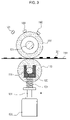
- FIG. 3 is a view illustrating a pressing roller pressed against a heating roller shown in FIG. 2 ;
- FIG. 4 is a view illustrating a pressing roller released from the heating roller in FIG. 2 ;
- FIG. 5 is a block diagram of a fixing system of the image forming apparatus according to an embodiment of the present general inventive concept.
- FIG. 6 is a view illustrating a control circuit controlling the operation of the pressure releasing unit of FIG. 5 .
- FIG. 2 is a perspective view illustrating a fixing system of an image forming apparatus according to an embodiment of the present general inventive concept.
- the fixing unit of the image forming apparatus according to the present invention includes a heating roller 100 , a pressing roller 110 , a pressing unit, a pressure releasing unit 130 , a first temperature sensing unit 140 , a second temperature sensing unit 150 , and a third temperature sensing unit 160 .
- the heating roller 100 is rotatably provided to fuse a toner to a sheet by heat.
- a heat lamp 101 is provided in the center of the heating roller 100 so that the heating roller 100 is heated by radiant heat from the heat lamp 101 .
- the pressing roller 110 is rotatably provided to face the heating roller 100 and presses a sheet toward the heating roller 100 .
- the pressing roller 110 is formed of rubber to smoothly press the sheet and includes a rotating shaft 111 making the pressing roller 110 rotatable therein.
- the pressing unit supports the rotating shaft 111 of the pressing roller 110 so that the pressing roller 110 can press the sheet to generate pressure.
- the pressing unit includes a U-shaped supporting guide 120 to support both ends of the rotating shaft 111 of the pressing roller 110 and a pressing spring 121 one side of which is coupled with the supporting guide 120 and the other side of which is coupled with the pressure releasing unit 130 to elastically support the supporting guide 120 and to generate pressure of a uniform magnitude toward the pressing roller 110 .
- the pressure releasing unit 130 includes a solenoid valve that can move up and down a plunger 131 by an electrical signal therein and that includes an end portion coupled to the other side of the pressing spring 121 .
- the solenoid valve When the solenoid valve is turned off, the plunger 131 supports the pressing spring 121 on the pressing spring 121 so that pressure of a uniform magnitude is generated by the pressing spring 121 .
- the solenoid valve When the solenoid valve is turned on, the plunger 131 falls down so that the pressure generated by the pressing spring 121 is released. Therefore, as illustrated in FIGS. 3 and 4 , the pressing roller 110 is pressed against the heating roller 100 when the solenoid valve is turned off and the pressing roller 110 is released from the heating roller 100 when the solenoid valve is turned on.
- FIG. 4 shows a gap between the pressing roller 110 and the heating roller 100 or a recording medium disposed between the pressing roller 110 and the heating roller 100 .
- the first temperature sensing unit 140 includes a first thermistor provided to contact an external circumference of the heating roller 100 and to sense a temperature of a surface of the heating roller 100 .
- the second temperature sensing unit 150 includes a second thermistor provided on one side of the heating roller 100 to be broken (i.e., in a malfunction or open state) when the heating roller 100 is overheated. An internal terminal of the second thermistor is opened when the temperature of the heating roller 100 is higher than a predetermined overheating temperature.
- the third temperature sensing unit 160 includes a thermostat provided to intercept a power source to the heat lamp 101 when the temperature of the heating roller 100 is higher than a predetermined critical temperature.
- the internal terminal of the thermostat is opened to intercept the power source supplied to the heat lamp 101 when the temperature of the heating roller 100 is higher than the predetermined critical temperature.
- FIG. 5 is a block diagram of a fixing system of an image forming apparatus according to an embodiment of the present general inventive concept.
- the fixing system of the image forming apparatus according to the present general inventive concept includes a driving unit 190 to drive the pressure releasing unit 130 to release releases the pressing roller 110 from the heating roller 100 , a first pressure releasing controller 170 to control an operation of the pressure releasing unit 130 by the driving unit 190 to read a temperature value of the heating roller 100 by the first temperature sensing unit 140 and to release the pressing roller 110 when the heating roller 100 is overheated, and a second pressure releasing controller 180 to control the operation of the pressing unit by the driving unit 190 to release the pressing roller 110 when the second temperature sensing unit 150 is broken.
- the driving unit 190 supplies a power source to the pressure releasing unit 130 or intercepts the power source from the pressure releasing unit 130 by a signal output from the first pressure releasing controller 170 or the second pressure releasing controller 180 to turn on or off the pressure releasing unit 130 .
- the first pressure releasing controller 170 includes a microcomputer 171 .
- the microcomputer 171 reads the voltage sensed by the first temperature sensing unit 140 by an analog-to-digital (A/D) port and compares the temperature corresponding to the read voltage value with the predetermined overheating temperature to turn on the pressure releasing unit 130 by the driving unit 190 and to release the pressing roller 110 from the heating roller 100 when it is determined that the temperature corresponding to the read voltage value is higher than the predetermined overheating temperature.
- temperature of the heating roller 100 can be controlled by controlling (or turning on and off) of the heat lamp 101 or controlling an electrical power supplied to the heat lamp 101 according to the temperature corresponding to the sensed voltage.
- the second pressure releasing controller 180 includes a comparing unit 181 and a switching unit 182 .
- the comparing unit 181 changes an output signal value by a change in a voltage generated when the second temperature sensing unit 150 is broken to turn on or off the switching unit 182 .
- the driving unit 190 operates to turn on or off the pressure releasing unit 130 .
- the first temperature sensing unit 140 and the second temperature sensing unit 150 may be negative temperature coefficient (NTC) thermistors in which a temperature and a resistance value are in inverse proportion to each other output a lower voltage value at a higher temperature.
- NTC negative temperature coefficient
- the voltage sensed by the first temperature sensing unit 140 sensing the temperature of the surface of the heating roller 100 is input to an A/D port THERM_IN of the microcomputer 171 .
- one side of the second temperature sensing unit 150 provided to be broken when the heating roller 100 is overheated so that the internal terminal thereof is opened when the temperature of the heating roller 100 is higher than the predetermined overheating temperature is connected to a “+” stage (terminal) of the comparing unit 181 and the other side of the second temperature sensing unit 150 is grounded. Therefore, the voltage sensed by the second temperature sensing unit 150 is caught in the “+” stage that is a non-inversion terminal of the comparing unit 181 and a reference voltage divided by a resistor R 3 and a resistor R 4 is caught in a “ ⁇ ” stage (terminal) that is an inversion terminal of the comparing unit 181 .
- the comparing unit 181 compares the voltage sensed by the second temperature sensing unit 150 that is caught in the “+” stage with the reference voltage caught in the “ ⁇ ” stage to output a first output value at a high level when it is determined that the sensed voltage is higher than the reference voltage and to output a second output value at a low level when the sensed voltage is no more than the reference voltage.
- the switching unit 182 including a transistor Q 1 is electrically connected to an output side of the comparing unit 181 .
- a base stage (terminal) of the transistor Q 1 is connected to the output side of the comparing unit 181 .
- An emitter stage (terminal) of the transistor Q 1 is grounded.
- a collector stage (terminal) of the transistor Q 1 is connected to the output port nFUSER_EN of the microcomputer 171 and the driving unit 190 . Therefore, the switching unit 182 is turned on when the output of the comparing unit 181 is at a high level and is turned off when the output of the comparing unit 181 is at a low level.
- the driving unit 190 including a transistor Q 2 is turned on to turn on the pressure releasing unit 130 when a gate stage is at a high level and is turned off to turn off the pressure releasing unit 130 when the gate stage is at a low level.
- the microcomputer 171 outputs a signal at a low level through the output port nFUSER_EN to turn off the driving unit 190 when the temperature corresponding to the voltage read from the first temperature sensing unit 140 is less than the predetermined overheating temperature. Therefore, since the pressure releasing unit 130 does not operate so that the pressure generated by the pressing spring 121 maintains a uniform magnitude, the pressing roller 110 is maintained to be pressed against the heating roller 100 . At this time, since the voltage sensed by the second temperature sensing unit 150 that is caught in the “+” stage of the comparing unit 181 is higher than the reference voltage caught in the “ ⁇ ” stage, a signal at a high level is output.
- the switching unit 182 is turned on by the signal at the high level so that the control performed by the microcomputer 171 is not affected. That is, even if there is a defect or damage on a connection between the first temperature sensing unit 140 and the microcomputer 171 or the driving unit 190 , the pressure releasing unit can be controlled by the driving unit to release the pressing roller 110 from the heating roller 100 according to information on a state of the second temperature sending unit 140 .
- the controlling of the driving unit 190 by the microcomputer 171 may include controlling a heating operation to maintain a desired temperature to fix a toner image 201 on the recording medium 200 by turning on and off the heating lamp 101 or controlling a voltage supplied to the heat lamp 101 .
- the microcomputer 171 outputs a signal at a high level through the output port nFUSER_EN to turn on the driving unit 190 when the temperature corresponding to the voltage read from the first temperature sensing unit 140 is no less than the predetermined overheating temperature. Therefore, the pressure releasing unit 130 operates so that the pressing roller 110 is released from the heating roller 100 .
- the microcomputer 171 may not turn on the driving unit 190 although the microcomputer 171 is supposed to turn on the driving unit 190 to operate the pressure releasing unit 130 . In such a case, the pressing roller 110 and the heating roller 100 are fusion-welded to each other.
- the thermostat is broken.
- the microcomputer 171 erroneously operates, since the second temperature sensing unit 150 is broken due to the overheat of the heating roller 100 , the output value of the comparing unit 181 is transited from high to low to turn off the switching unit 182 . Therefore, since the driving unit 190 is turned on to operate the pressure releasing unit 130 , the pressing roller 110 can be forcibly released from the heating roller 100 . Therefore, even if the microcomputer 171 erroneously operates, the pressing roller 110 and the heating roller 100 can be prevented from being fused to each other.
- the image forming apparatus in which the heating roller and the pressing roller are provided to be released from each other, includes the temperature sensing unit which is broken when the heating roller is overheated and the pressure releasing control unit provided to release the pressing roller from the heating roller when the temperature sensing unit is broken.
- the pressing roller is forcibly released from the heating roller by means of the pressure releasing control unit, preventing the heating roller and the pressing roller from being fused to each other.
Landscapes
- Physics & Mathematics (AREA)
- General Physics & Mathematics (AREA)
- Engineering & Computer Science (AREA)
- Microelectronics & Electronic Packaging (AREA)
- Fixing For Electrophotography (AREA)
Abstract
Description
Claims (15)
Applications Claiming Priority (3)
| Application Number | Priority Date | Filing Date | Title |
|---|---|---|---|
| KR1020070010666A KR20080072219A (en) | 2007-02-01 | 2007-02-01 | Image Forming Device |
| KR10-2007-0010666 | 2007-02-01 | ||
| KR2007-10666 | 2007-02-01 |
Publications (2)
| Publication Number | Publication Date |
|---|---|
| US20080187333A1 US20080187333A1 (en) | 2008-08-07 |
| US8095023B2 true US8095023B2 (en) | 2012-01-10 |
Family
ID=39676267
Family Applications (1)
| Application Number | Title | Priority Date | Filing Date |
|---|---|---|---|
| US12/021,596 Expired - Fee Related US8095023B2 (en) | 2007-02-01 | 2008-01-29 | Image forming apparatus |
Country Status (3)
| Country | Link |
|---|---|
| US (1) | US8095023B2 (en) |
| KR (1) | KR20080072219A (en) |
| CN (1) | CN100594446C (en) |
Families Citing this family (4)
| Publication number | Priority date | Publication date | Assignee | Title |
|---|---|---|---|---|
| JP2008298989A (en) * | 2007-05-30 | 2008-12-11 | Canon Inc | Image forming apparatus and fixing device control method |
| CN103235614B (en) * | 2013-05-13 | 2015-04-01 | 上海富士施乐有限公司 | Safety control circuit of thermal fixer |
| JP6332148B2 (en) * | 2015-05-29 | 2018-05-30 | 京セラドキュメントソリューションズ株式会社 | Image forming apparatus |
| JP6589789B2 (en) * | 2016-09-21 | 2019-10-16 | 京セラドキュメントソリューションズ株式会社 | Image forming apparatus |
Citations (3)
| Publication number | Priority date | Publication date | Assignee | Title |
|---|---|---|---|---|
| US5754917A (en) * | 1997-04-11 | 1998-05-19 | Xerox Corporation | High temperature safety system for a fusing subsystem module for an electrophotographic printer |
| CN1677273A (en) | 2004-03-31 | 2005-10-05 | 佳能株式会社 | Image forming apparatus |
| KR20050117439A (en) | 2004-06-10 | 2005-12-14 | 삼성전자주식회사 | Fixing apparatus of image forming equipment and jam removal method of image forming equipment using the same |
-
2007
- 2007-02-01 KR KR1020070010666A patent/KR20080072219A/en not_active Ceased
-
2008
- 2008-01-29 US US12/021,596 patent/US8095023B2/en not_active Expired - Fee Related
- 2008-01-31 CN CN200810008932A patent/CN100594446C/en not_active Expired - Fee Related
Patent Citations (4)
| Publication number | Priority date | Publication date | Assignee | Title |
|---|---|---|---|---|
| US5754917A (en) * | 1997-04-11 | 1998-05-19 | Xerox Corporation | High temperature safety system for a fusing subsystem module for an electrophotographic printer |
| CN1677273A (en) | 2004-03-31 | 2005-10-05 | 佳能株式会社 | Image forming apparatus |
| US20050220467A1 (en) * | 2004-03-31 | 2005-10-06 | Canon Kabushiki Kaisha | Image forming apparatus |
| KR20050117439A (en) | 2004-06-10 | 2005-12-14 | 삼성전자주식회사 | Fixing apparatus of image forming equipment and jam removal method of image forming equipment using the same |
Non-Patent Citations (1)
| Title |
|---|
| Chinese Office Action issued Jun. 5, 2009 in CN Application No. 200810008932.5. |
Also Published As
| Publication number | Publication date |
|---|---|
| CN101236397A (en) | 2008-08-06 |
| KR20080072219A (en) | 2008-08-06 |
| US20080187333A1 (en) | 2008-08-07 |
| CN100594446C (en) | 2010-03-17 |
Similar Documents
| Publication | Publication Date | Title |
|---|---|---|
| US7030345B2 (en) | Image heating apparatus having a heat generation member generating heat by magnetic flux and heating an image on a recording material | |
| US20090252521A1 (en) | Image fixing apparatus | |
| JP4557623B2 (en) | Image forming apparatus | |
| US8095023B2 (en) | Image forming apparatus | |
| CN101271310B (en) | Image forming apparatus | |
| US5737664A (en) | Overheating prevention device for a fixing unit | |
| US7761016B2 (en) | Overheating control and method in an image forming apparatus | |
| JP2003057116A (en) | Temperature detection method | |
| US7499658B2 (en) | Image forming apparatus including at least two thermostats to prevent overheating of the heating roller | |
| US20100142978A1 (en) | Fixing device | |
| US11573512B2 (en) | Image forming apparatus with heating device, heating device with fixing belt, and heating control method for heating device | |
| JP2003005572A (en) | Image heating device | |
| JP2004028622A (en) | Temperature detection device and image forming device | |
| JPH05333740A (en) | Image fixing device | |
| JP7263022B2 (en) | Heating device, fixing device and image forming device | |
| JP4066125B2 (en) | Fail-safe circuit and image forming apparatus | |
| JP2026019595A (en) | Image forming apparatus and method for detecting wrapping around fixing belt | |
| KR100366030B1 (en) | Method for controlling temperature of fusing device | |
| JP2001290383A (en) | Image forming device | |
| JPH07271236A (en) | Thermal fixing device | |
| JPH11109838A (en) | Image forming device | |
| JPH02115863A (en) | image forming device | |
| JP2001282038A (en) | Image forming device | |
| JPH09230756A (en) | Cooling system and image forming device | |
| JPH10319776A (en) | Roller device |
Legal Events
| Date | Code | Title | Description |
|---|---|---|---|
| AS | Assignment |
Owner name: SAMSUNG ELECTRONICS CO., LTD., KOREA, REPUBLIC OF Free format text: ASSIGNMENT OF ASSIGNORS INTEREST;ASSIGNOR:HWANG, JONG IN;REEL/FRAME:020430/0949 Effective date: 20070430 |
|
| ZAAA | Notice of allowance and fees due |
Free format text: ORIGINAL CODE: NOA |
|
| ZAAB | Notice of allowance mailed |
Free format text: ORIGINAL CODE: MN/=. |
|
| STCF | Information on status: patent grant |
Free format text: PATENTED CASE |
|
| FEPP | Fee payment procedure |
Free format text: PAYOR NUMBER ASSIGNED (ORIGINAL EVENT CODE: ASPN); ENTITY STATUS OF PATENT OWNER: LARGE ENTITY |
|
| FPAY | Fee payment |
Year of fee payment: 4 |
|
| AS | Assignment |
Owner name: S-PRINTING SOLUTION CO., LTD., KOREA, REPUBLIC OF Free format text: ASSIGNMENT OF ASSIGNORS INTEREST;ASSIGNOR:SAMSUNG ELECTRONICS CO., LTD;REEL/FRAME:041852/0125 Effective date: 20161104 |
|
| AS | Assignment |
Owner name: HP PRINTING KOREA CO., LTD., KOREA, REPUBLIC OF Free format text: CHANGE OF NAME;ASSIGNOR:S-PRINTING SOLUTION CO., LTD.;REEL/FRAME:047370/0405 Effective date: 20180316 |
|
| AS | Assignment |
Owner name: HP PRINTING KOREA CO., LTD., KOREA, REPUBLIC OF Free format text: CORRECTIVE ASSIGNMENT TO CORRECT THE DOCUMENTATION EVIDENCING THE CHANGE OF NAME PREVIOUSLY RECORDED ON REEL 047370 FRAME 0405. ASSIGNOR(S) HEREBY CONFIRMS THE CHANGE OF NAME;ASSIGNOR:S-PRINTING SOLUTION CO., LTD.;REEL/FRAME:047769/0001 Effective date: 20180316 |
|
| MAFP | Maintenance fee payment |
Free format text: PAYMENT OF MAINTENANCE FEE, 8TH YEAR, LARGE ENTITY (ORIGINAL EVENT CODE: M1552); ENTITY STATUS OF PATENT OWNER: LARGE ENTITY Year of fee payment: 8 |
|
| AS | Assignment |
Owner name: HP PRINTING KOREA CO., LTD., KOREA, REPUBLIC OF Free format text: CHANGE OF LEGAL ENTITY EFFECTIVE AUG. 31, 2018;ASSIGNOR:HP PRINTING KOREA CO., LTD.;REEL/FRAME:050938/0139 Effective date: 20190611 |
|
| AS | Assignment |
Owner name: HEWLETT-PACKARD DEVELOPMENT COMPANY, L.P., TEXAS Free format text: CONFIRMATORY ASSIGNMENT EFFECTIVE NOVEMBER 1, 2018;ASSIGNOR:HP PRINTING KOREA CO., LTD.;REEL/FRAME:050747/0080 Effective date: 20190826 |
|
| FEPP | Fee payment procedure |
Free format text: MAINTENANCE FEE REMINDER MAILED (ORIGINAL EVENT CODE: REM.); ENTITY STATUS OF PATENT OWNER: LARGE ENTITY |
|
| LAPS | Lapse for failure to pay maintenance fees |
Free format text: PATENT EXPIRED FOR FAILURE TO PAY MAINTENANCE FEES (ORIGINAL EVENT CODE: EXP.); ENTITY STATUS OF PATENT OWNER: LARGE ENTITY |
|
| STCH | Information on status: patent discontinuation |
Free format text: PATENT EXPIRED DUE TO NONPAYMENT OF MAINTENANCE FEES UNDER 37 CFR 1.362 |
|
| FP | Lapsed due to failure to pay maintenance fee |
Effective date: 20240110 |