US80949A - Chaeles j - Google Patents
Chaeles j Download PDFInfo
- Publication number
- US80949A US80949A US80949DA US80949A US 80949 A US80949 A US 80949A US 80949D A US80949D A US 80949DA US 80949 A US80949 A US 80949A
- Authority
- US
- United States
- Prior art keywords
- spindle
- arm
- flier
- traverse
- bobbin
- Prior art date
- Legal status (The legal status is an assumption and is not a legal conclusion. Google has not performed a legal analysis and makes no representation as to the accuracy of the status listed.)
- Expired - Lifetime
Links
- 241001155433 Centrarchus macropterus Species 0.000 description 11
- 238000009987 spinning Methods 0.000 description 5
- 238000010276 construction Methods 0.000 description 4
- 239000002184 metal Substances 0.000 description 3
- 241001155430 Centrarchus Species 0.000 description 2
- 239000002657 fibrous material Substances 0.000 description 2
- 238000004519 manufacturing process Methods 0.000 description 2
- 239000000463 material Substances 0.000 description 2
- 241000220010 Rhode Species 0.000 description 1
- 230000013011 mating Effects 0.000 description 1
- 238000004804 winding Methods 0.000 description 1
Images

Classifications
-
- D—TEXTILES; PAPER
- D01—NATURAL OR MAN-MADE THREADS OR FIBRES; SPINNING
- D01H—SPINNING OR TWISTING
- D01H7/00—Spinning or twisting arrangements
- D01H7/02—Spinning or twisting arrangements for imparting permanent twist
- D01H7/24—Flyer or like arrangements
- D01H7/26—Flyer constructions
Definitions
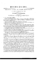
- Figure 1 is an elevation of a spindle and ilier-constructed'with my improvement.
- Figure 2 is a top-view below the line :v y of fig. I, showing in section the bobb-in, the surrounding iier, the traverse-arm and block,and the guide for such block on the traverse-rail.
- Figure 8 is a top view of the flier, hier-arm, and hobbin.
- the invention hereinafter described relates to machinery for spinning fibrous material, from suitablyprepared roving, into thread or yarn, and'embodies certain improvements,ithe end of which is to obtain, in thc same machine,l all the capacity ofthe ier-frame spinning-machine to manufacture ne and evenly-twisted yarns -of high numbers and grade, with all the. rapidity of production which characterizes'thering-spinning frame. l
- the hollowflier-shaft or spindle D Surrounding the spindle A is the hollowflier-shaft or spindle D, which is properly bolstered, and should have a sufiicicnt extent of journal-bearing surface 'in the frame B to insure perfect steadiness of movement under all conditions oi" speed.
- the upper end .of this flier-shaft is furnished with-a hier ofpeculiar construction. It consists cfa cylindrical barrel, a, ofthin metal, with' apertures, hereinafter mentioned, and is of suiiicient lengthand internal diameter to accommodate the bobbin C upon the spindle A.
- This hier is caused to revolve with great rapidity about the spindle, but, unlike all other fliers, it always revolves inthe same plane relatively to thc bobbin, whereby all the disturbances incident to a shifting or variable extent of bearing are avoided, and the highest practicable number of turns can be given to it without ill eiiects.
- the roving or yarn to he spun may be presented to' the flier in a line coincident with the axis oi the spindle, there is hinged to the top rim of the hier an arm, I), furnished at its end with a guiding-eye, e, for the yarn.
- This arm is hinged, instead of being rigidly attached to theier, fonconveniencein doing the iilled bobbin, or setting an empty one upon the spindle.)
- the joint of thehingeiwhieh attaches the arm to the flier, should 'be so constructed-that whensuch arm is in proper position for.
- the iiier constantly lrevolves in the same plane.
- thc'traverse-rail E,linstead ⁇ of being ⁇ connected. with the iiier isr connected with a device which may be called a travelling traverse-arm, and gives to the same a'movcment up and down, parallel with the core .of the bobbin, independent of the movement in a circle which it obtains 'from the iier.
- the said traverse-arm, cZ furnished with a thread-guide at its ⁇ end, projects, in a curved line concentric with the flier, from a traverseblock, e, which block is furnished with a groove, so as tov embrace theA circular edge of ⁇ the plate F, let into. the top of the vtraverse-rail, and a lip,f, (fig. 2,) projecting 'from such block, enters a longitudinal slit in the hier, extending the Whole length of the range of motion -of the traverserail.
- the traverse-block and itsA arm CZ will revolve with the flier in a circular path, while the plane in which it revolves will-be controlled bythe traverse-rail, the flier revolvingin a constant plane.
- a. longitudinal opening, g should be made in theside of the flier, extending the whole length of the bobbing and in order to distribute equally about its axis .the weight of metal in the iei, it will be well to balance it by removing a piece of metal of corresponding size from. the side of the flier opposite to the aperture g, as seen at h, g. 2.
- the material to be spun is to be conducted -in a. well-known way from the delivering-rollers to the eyee in the end of the dier-arm b; and in order to bring the same to the said eye in a line coincident with the axisy of theiier produced, guides of common construction are arranged to stand directly over the eyes in thelier-arms.
Landscapes
- Engineering & Computer Science (AREA)
- Mechanical Engineering (AREA)
- Textile Engineering (AREA)
- Spinning Or Twisting Of Yarns (AREA)
Description
HTM V y INVENTQR- N.PETERS. PHOTO-LITHOGRAPHER. WASHINGTON. D C.
@ditch taten @anni @Hita Leners Parmi No. Sacagawea August 11, 186e` IMPRQVBMNT IN SPINING-M'AGHINB.
@in .Stigsmtlt rerum tu im tiges-e ldtntrtmt mn mating un uf tige stmt.
TO ALL WHOM IT MAY CONCERN: l
Be it known that L'ClnsnLns J. HARRIS, of Warren, in the county of Bristol, and State of Rhode Island, have invented a new and useful Improvement in Machinery for Spinning Fibrous Material; and I do hereby declare that the following specification, takenin connection with the drawings making a part of-the same, is a,
full, clear, and exact description thereof. v y
Figure 1 is an elevation of a spindle and ilier-constructed'with my improvement.
Figure 2 is a top-view below the line :v y of fig. I, showing in section the bobb-in, the surrounding iier, the traverse-arm and block,and the guide for such block on the traverse-rail.
Figure 8 is a top view of the flier, hier-arm, and hobbin.
The invention hereinafter described relates to machinery for spinning fibrous material, from suitablyprepared roving, into thread or yarn, and'embodies certain improvements,ithe end of which is to obtain, in thc same machine,l all the capacity ofthe ier-frame spinning-machine to manufacture ne and evenly-twisted yarns -of high numbers and grade, with all the. rapidity of production which characterizes'thering-spinning frame. l
The distinguishing features of my improvementsmay be said to consist- In the employment of a flierof peculiar construction, in combination with a spindle, which Hier and spindle do not change, during the filling of the bobbin, their relative positions.
Also' in the employment of a peculiar device, in combination with the ilier,-for presenting the 'material to be spun to the action ofthe iier, which shall cause the same, while being twisted, and until converted into thread' or yarn, to pursue aline of travel which is free'lfrom any gyratory movement.
The essential parts of the apparatus employed are set out in the following description.
A description ofthe invention, as applied to a single spindle, must be understood to be thesam'e for all the` other-spindles in a frame. In all other respects, too, where n ot otherwise mentioned, it is to be implied'tha-t.
the machine is to be constructed, arranged, andhave motion communicated to the operating parts in any ofthe well-known ways. I 'l A spindle, A, of ordinary construction, is properly stepped and bolstered in a suitable frame, B. Upon its upper end it carries a bobbin, C. The spindle is of theclass technically known as dead spindles, or those which are not driven by the direct application of power, but whose movement is incidental only to the movement of their fliers. p
Surrounding the spindle A is the hollowflier-shaft or spindle D, which is properly bolstered, and should have a sufiicicnt extent of journal-bearing surface 'in the frame B to insure perfect steadiness of movement under all conditions oi" speed. The upper end .of this flier-shaft is furnished with-a hier ofpeculiar construction. It consists cfa cylindrical barrel, a, ofthin metal, with' apertures, hereinafter mentioned, and is of suiiicient lengthand internal diameter to accommodate the bobbin C upon the spindle A. This hier is caused to revolve with great rapidity about the spindle, but, unlike all other fliers, it always revolves inthe same plane relatively to thc bobbin, whereby all the disturbances incident to a shifting or variable extent of bearing are avoided, and the highest practicable number of turns can be given to it without ill eiiects.
In order that the roving or yarn to he spun may be presented to' the flier in a line coincident with the axis oi the spindle, there is hinged to the top rim of the hier an arm, I), furnished at its end with a guiding-eye, e, for the yarn. This arm is hinged, instead of being rigidly attached to theier, fonconveniencein doing the iilled bobbin, or setting an empty one upon the spindle.) The joint of thehingeiwhieh attaches the arm to the flier, should 'be so constructed-that whensuch arm is in proper position for. the spinning of yarn, the eye in the end of the same will be directly over the axis of the spindle, and consequently the arm will stand atan angle with the line of theaxis of tho spindle produced, so as to describe, as thev flier revolves, the ,figure of'a'cone.
As has been already stated, the iiier constantly lrevolves in the same plane. In order that the yarn may be wound upon the bobbin, thc'traverse-rail E,linstead`of being `connected. with the iiier, isr connected with a device which may be called a travelling traverse-arm, and gives to the same a'movcment up and down, parallel with the core .of the bobbin, independent of the movement in a circle which it obtains 'from the iier. In the present instance the said traverse-arm, cZ, furnished with a thread-guide at its` end, projects, in a curved line concentric with the flier, from a traverseblock, e, which block is furnished with a groove, so as tov embrace theA circular edge of `the plate F, let into. the top of the vtraverse-rail, and a lip,f, (fig. 2,) projecting 'from such block, enters a longitudinal slit in the hier, extending the Whole length of the range of motion -of the traverserail. Obviously the traverse-block and itsA arm CZ will revolve with the flier in a circular path, while the plane in which it revolves will-be controlled bythe traverse-rail, the flier revolvingin a constant plane.
To enable the thread to run from the hook on the end of the traverse-arm cl to the bobbin, a. longitudinal opening, g, should be made in theside of the flier, extending the whole length of the bobbing and in order to distribute equally about its axis .the weight of metal in the iei, it will be well to balance it by removing a piece of metal of corresponding size from. the side of the flier opposite to the aperture g, as seen at h, g. 2.
It is also to be understood that the material to be spun is to be conducted -in a. well-known way from the delivering-rollers to the eyee in the end of the dier-arm b; and in order to bring the same to the said eye in a line coincident with the axisy of theiier produced, guides of common construction are arranged to stand directly over the eyes in thelier-arms. As only that por'tionof the roving receives the twist which is located between the eyein thelier-arm `and the deliveringirollers, it will be apparent to all familiar with spinning-machinery, that if conductedyas above described, -the yarn, while receiving its twist, will travel in a dead line, or, in other words, a line which is free from-any gyratory motion.
What I claim as my invention, `and desire to secure'by Letters Patent, is-
1. A cylindrical Bier, a, witha thread-guiding arm, b, hinged thereto, constructed substantially as herein described. l Y..
2. The arrangement of the flier a `b, constructed as described, with the spindle A, to which it appertains,
so that the relation of the two shall remain unchanged, by causing both lto remain in fixed planes during thev spinning operation, and the winding up'of the bobbin, substantially as herein set forth.
l 3. The combination of the flier ab, the independent traverse-arm d, the block e, all constructed as described7 with a suitably-operated traverse-rail, E, lsubstantially as described. v
CHARLES J. HARRIS.
Witnesses:
WLLIAM W. B ICKARD, C. L. PENLEToN.
Publications (1)
| Publication Number | Publication Date |
|---|---|
| US80949A true US80949A (en) | 1868-08-11 |
Family
ID=2150444
Family Applications (1)
| Application Number | Title | Priority Date | Filing Date |
|---|---|---|---|
| US80949D Expired - Lifetime US80949A (en) | Chaeles j |
Country Status (1)
| Country | Link |
|---|---|
| US (1) | US80949A (en) |
Cited By (1)
| Publication number | Priority date | Publication date | Assignee | Title |
|---|---|---|---|---|
| US20040160428A1 (en) * | 2003-02-14 | 2004-08-19 | Prosenjit Ghosh | Positioning mechanism for a pen-based computing system |
-
0
- US US80949D patent/US80949A/en not_active Expired - Lifetime
Cited By (1)
| Publication number | Priority date | Publication date | Assignee | Title |
|---|---|---|---|---|
| US20040160428A1 (en) * | 2003-02-14 | 2004-08-19 | Prosenjit Ghosh | Positioning mechanism for a pen-based computing system |
Similar Documents
| Publication | Publication Date | Title |
|---|---|---|
| US80949A (en) | Chaeles j | |
| US959198A (en) | Spinning and twisting frame. | |
| US2500827A (en) | Flyer for spinning frame | |
| US212725A (en) | Improvement in spindles for spinning-machines | |
| US539561A (en) | Abeam whitakee | |
| US745030A (en) | Spinning-frame. | |
| US89290A (en) | Improvement in twisting- and drawing-heads for spinning-machines | |
| US494723A (en) | Kothen | |
| US232818A (en) | harris | |
| US330035A (en) | Island | |
| US409959A (en) | g-essnee | |
| US506754A (en) | Apparatus for spinning or twisting | |
| US5851A (en) | Machinery for doubling and twisting tarn | |
| US340159A (en) | Ring-spinning frame | |
| US391959A (en) | Spindle and flier | |
| US42307A (en) | Improvement in spinning-machines | |
| US617678A (en) | emery | |
| US959316A (en) | Spinning and twisting machine. | |
| US488136A (en) | Cyrus a | |
| US784753A (en) | Machine for covering wire. | |
| US948320A (en) | Yarn-winding machine. | |
| US805238A (en) | Spinning-machine. | |
| US806016A (en) | Spinning-frame. | |
| US829467A (en) | Traverse-guide for doubling and twisting machines. | |
| US59120A (en) | Improvement in machines for making fishing-lines and other small cords |