US809473A - Acetylene-gas plant. - Google Patents
Acetylene-gas plant. Download PDFInfo
- Publication number
- US809473A US809473A US23517604A US1904235176A US809473A US 809473 A US809473 A US 809473A US 23517604 A US23517604 A US 23517604A US 1904235176 A US1904235176 A US 1904235176A US 809473 A US809473 A US 809473A
- Authority
- US
- United States
- Prior art keywords
- gas
- gasometer
- pipe
- water
- basin
- Prior art date
- Legal status (The legal status is an assumption and is not a legal conclusion. Google has not performed a legal analysis and makes no representation as to the accuracy of the status listed.)
- Expired - Lifetime
Links
- XLYOFNOQVPJJNP-UHFFFAOYSA-N water Substances O XLYOFNOQVPJJNP-UHFFFAOYSA-N 0.000 description 17
- 238000010276 construction Methods 0.000 description 4
- 238000007789 sealing Methods 0.000 description 3
- 239000007788 liquid Substances 0.000 description 2
- 238000005192 partition Methods 0.000 description 2
- 239000004568 cement Substances 0.000 description 1
- 238000000354 decomposition reaction Methods 0.000 description 1
- 239000000463 material Substances 0.000 description 1
- 230000004048 modification Effects 0.000 description 1
- 238000012986 modification Methods 0.000 description 1
Images

Classifications
-
- C—CHEMISTRY; METALLURGY
- C10—PETROLEUM, GAS OR COKE INDUSTRIES; TECHNICAL GASES CONTAINING CARBON MONOXIDE; FUELS; LUBRICANTS; PEAT
- C10H—PRODUCTION OF ACETYLENE BY WET METHODS
- C10H15/00—Acetylene gas generators with carbide feed, with or without regulation by the gas pressure
- C10H15/20—Acetylene gas generators with carbide feed, with or without regulation by the gas pressure with carbide feed by cartridges or other packets
Definitions
- My invention relates to acetylene-gas plants of large capacitysuch as are adapted for use to supply villages, towns, or large buildings with gas; and it has for its object to improve the same in point of simplicity, durabilty, ease of manipulation, and general efiiciency.
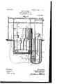
- Figure 1 is a plan view with some parts in horizontal section, illustrating a gas plant embodying the several features of my invention.
- Fig. 2 is a vertical section taken approximately
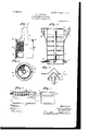
- Fig. 3 is a detail view, partly in side elevation and partly in vertical section. showing one of the improved generating shells or domes and a carbid-holder held within the same.
- Fig. 4 is a horizontal section on the line at as of Fig. 3.
- Fig. 5 is a vertical section taken on the line 00 m of Fig.1.
- Fig. 6 is a vertical section on the line or w of Fig. 1.
- Fig. 7 is a section takenvon the line as m of Fig. 6, and
- Fig. 8 is a detail taken through a portion of the gasometer on the line 00 x of Fig. 1.
- the numeral 1 indicates the walls, and the numeral 2 the ceiling, of the gas-house, the same, as shown, having a concrete or cement floor 3.
- a gasometer well or seat 4 Formed monolithic with the floor 3, and depending therefrom and set into the ground, is a gasometer well or seat 4, a generator-basin 5, and a dry well 6.
- the movable gasometer 7 works within the well 4, is seated in water contained therein, and is guided for true vertical movements by vertical guide-posts 8, anchored in the floor 3 and ceiling 2, and over which run grooved guidewheels 9, mounted in bearings 10, rigid on the upper'portion of the gasometer 7.
- a gas chamber afforded by a metallic reservoir or tank 11, is embedded in the concrete H V of the thick bottom of the generator-basin 5 and is provided with a plurality of stand-pipes 12, the ends of which depend into said tank and are sealed by water 2, contained in said tank.
- the generator-basin 5 is filled with water, preferably, up to the level marked by the line .2 in Fig. 2, and it will be noted that the stand-pipes 12 project upward considerably above this level.
- a gas-delivery pipe 13 extends from the upfirst horizontally into the dry well 6, thence vertically upward to above the floor-level and from thence to a washer, which is indicated as an entirety by the numeral 1 1,
- a pipe 15 connects the washer 14 with the interior of the gasometer, and this pipe extends down through the dry well 6 to a point near the bottom thereof, thence horizontally under the gasometer, and thence axially upward into the same to a point above the waterlevel thereof.
- An outlet-pipe 16 extends downward from the interior of the gasometer from a point above the water-level thereof to a point near the bottom of the dry well 6, thence horizontally into-said dry well, thence upward through the dry well to a point above the floor, thence horizontally to a filter 17 the preferred construction of which will be considered later on.
- a service-pipe 18 leads from the filter 17 and is provided with a back passage 19, afforded by a pipe which leads directly from the pipe 16.
- valves 16, 18, and 19 in the pipes 16, 18, and 19, respectively By the manipulation of valves 16, 18, and 19 in the pipes 16, 18, and 19, respectively, the gas may be caused to pass through the filter or directly through the bypass 19, as may be desired.
- the gas In the elbow portions of the pipes 13, 15, and 16 are depending U-shaped traps or water seals 20, which contain water or other sealing liquid and the upturned ends of which are open. These seals 20 are all located in the dry well 6.
- the numeral 21 indicates a vent-pipe which extends from within the gasometer into the dry well 6 and from thence upward to some suitable point for exhaust. At its elbow portion the vent-pipe 21 within the dry well is provided with sealing-trap 20
- Thenumeral 22 indicatesa drain-pipe which extends from the reservoir 11 into the dry well and is adapted to be closed by a cap 22*.
- This washer acts as a purifier to relieve the gas from foreign matter and as a condenser to condense vaporous matter.
- the so-called filter 17 is illustrated in Fig. 5, wherein the case or shell thereof is provided with a plurality of horizontal partitions 24, of hair, felt, or similar material, through which the gas is caused to pass and by which it is relieved of moisture and other foreign matter and is dried.
- the upper end of the filter-case is closed by a cover 25, which has a depending flange 26, that is seated in a sealing liquid 27, contained in an annular seat 28 on the said case.
- the delivery end of the pipe 15 within the gasometer is provided with a conical hood 29, the depending flange of which has perforations 30, which perforations are slightly below the water-level within the gasometer.
- vent-pipe 21 works loosely within a sleeve 31, carried by the head of the gasometer 7
- the upper end of this sleeve 31 is closed and the lower end thereof depends into the water in the gasometer, thereby sealing the vent-pipe 21 at all times except when the gasometer? is raised to an extreme elevation, whereupon the said vent-pipe is open.
- a guide-rail 32 extends horizontally over the upper ends of the stand-pipes 12 and at its ends is rigidly secured to the walls of the gas-house 1.
- On this rail runs a small truck 33, which carries a block-and-tackle hoisting device 34.
- a generator shell or dome provided within with a carbid-holder.
- a generating-dome of the preferred construction is shown in detail in Figs. 3 and 4, wherein the numeral 35 inclicates the dome, the lower end of which is open and the closed upper end of which is contracted, giving the device very much the form of a bell.
- the carbid-holder 36 which is of cylindrical form, fits telescopically within the enlarged portion of the dome 35 and is provided with an axial guide-tube 37, through which the upper end of one of the stand-pipes 12 is adapted to pass freely.
- lock-rods 38 are, as shown, journaled in the sides of the dome 35 and are provided at their lower ends with laterally-projecting rest-lugs 39 and at their upper ends with finger-pieces 40.
- the rest-lugs 39 when turned under the lower hoop of the carbid-holder 36 securely hold the carbid-holder in position.
- the domes 35 are provided with hooks 41, which adapt them to be readily attached to the hoisting device 34, bymeans of which hoisting device they may be readily carried to and from working and filling positions.
- their carbidholders When in working positions, their carbidholders are of course filled, and they are telescoped onto the upper ends of the stand-pipes 12, as already described.
- domes 35 are provided with laterally-projecting supporting-flanges 42, that are adapted to be rested upon a ledge 43 of the generatorbasin 5 to hold said domes with their open lower ends submerged in the water 2 within the basin 5, but with their vcarbid-holders elevated above the surface of said water.
- it is simply turned far enough to cause its supportingflange 42 to clear the ledge 43, thereby permitting the said dome to drop and throw its carbid-holder into the said water 2.
- the carbid-holders 36 are arranged to contain enough carbid to generate gassufficient to approximately fill the gasometer, and hence it will of course be understood that it is not necessary to very frequently throw the several generating devices successively into action.
- the numeral 44 indicates a drain-pipe which extends from the basin 5 into a residuum-receiving tank or well 45. By the circulation of water the residuum or products of decomposition may be washed from the basin 5 into the well 45.
Landscapes
- Chemical & Material Sciences (AREA)
- Oil, Petroleum & Natural Gas (AREA)
- Organic Chemistry (AREA)
- Filling Or Discharging Of Gas Storage Vessels (AREA)
Description
No. 809,473. PATENTED JAN. 9, 1906. W. J. STINSON.
AGETYLENE GAS PLANT.
APPLICATION FILED DEC. 2, 1904.
3 SHEETSSHEET 1.
PATENTED JAN. 9, 1906.
APPLIOATION FILED DEC. 2. 1904.
3 SHEETS-SHEET 2.
P FW/Wwes PATENTED JAN. 9, 1906.
J. STINSON. AGETYLBNE GAS PLANT.
APPLICATION FILED DEC. 2, 1904.
3 SHEETSSHBBT 3,
0O O o O O 0 Mo 00 0 o o o O 11 1/111 111 II I I .on the line m m of Fig. 1.
UNITED STATES PATENT OFFICE.
Specification of Letters Patent.
Patented Jan. 9, 1906.
Application fil d, December 2,1904. Serial No. 235,176.
To all whom it may concern:
Be it known that I, WVILLIAM J. STINsoN, a citizen of the United States, residing at Minneapolis, in the county of Hennepin and State of Minnesota, have invented certain new and useful Improvements in Acetylene-Gas Plants; and I do hereby declare the following to be a full, clear, and exact description of the invention, such as will enable others skilled in the art to which it appertains to make and use the same.
My invention relates to acetylene-gas plants of large capacitysuch as are adapted for use to supply villages, towns, or large buildings with gas; and it has for its object to improve the same in point of simplicity, durabilty, ease of manipulation, and general efiiciency.
The invention consists of the novel devices and combinations of devices hereinafter described, and defined in the claims. K
In the accompanying drawings, which illustrate my invention, likecharacters indicate like parts throughout the several views.
Figure 1 is a plan view with some parts in horizontal section, illustrating a gas plant embodying the several features of my invention. Fig. 2 is a vertical section taken approximately Fig. 3 is a detail view, partly in side elevation and partly in vertical section. showing one of the improved generating shells or domes and a carbid-holder held within the same. Fig. 4 is a horizontal section on the line at as of Fig. 3. Fig. 5 is a vertical section taken on the line 00 m of Fig.1. Fig. 6 is a vertical section on the line or w of Fig. 1. Fig. 7 is a section takenvon the line as m of Fig. 6, and Fig. 8 is a detail taken through a portion of the gasometer on the line 00 x of Fig. 1.
The numeral 1 indicates the walls, and the numeral 2 the ceiling, of the gas-house, the same, as shown, having a concrete or cement floor 3. Formed monolithic with the floor 3, and depending therefrom and set into the ground, is a gasometer well or seat 4, a generator-basin 5, and a dry well 6. The movable gasometer 7 works within the well 4, is seated in water contained therein, and is guided for true vertical movements by vertical guide-posts 8, anchored in the floor 3 and ceiling 2, and over which run grooved guidewheels 9, mounted in bearings 10, rigid on the upper'portion of the gasometer 7.
A gas chamber, afforded by a metallic reservoir or tank 11, is embedded in the concrete H V of the thick bottom of the generator-basin 5 and is provided with a plurality of stand-pipes 12, the ends of which depend into said tank and are sealed by water 2, contained in said tank. The generator-basin 5 is filled with water, preferably, up to the level marked by the line .2 in Fig. 2, and it will be noted that the stand-pipes 12 project upward considerably above this level.
A gas-delivery pipe 13 extends from the upfirst horizontally into the dry well 6, thence vertically upward to above the floor-level and from thence to a washer, which is indicated as an entirety by the numeral 1 1,
and the preferred form of which will be later noted. A pipe 15 connects the washer 14 with the interior of the gasometer, and this pipe extends down through the dry well 6 to a point near the bottom thereof, thence horizontally under the gasometer, and thence axially upward into the same to a point above the waterlevel thereof. An outlet-pipe 16 extends downward from the interior of the gasometer from a point above the water-level thereof to a point near the bottom of the dry well 6, thence horizontally into-said dry well, thence upward through the dry well to a point above the floor, thence horizontally to a filter 17 the preferred construction of which will be considered later on. A service-pipe 18 leads from the filter 17 and is provided with a back passage 19, afforded by a pipe which leads directly from the pipe 16. By the manipulation of valves 16, 18, and 19 in the pipes 16, 18, and 19, respectively, the gas may be caused to pass through the filter or directly through the bypass 19, as may be desired. In the elbow portions of the pipes 13, 15, and 16 are depending U-shaped traps or water seals 20, which contain water or other sealing liquid and the upturned ends of which are open. These seals 20 are all located in the dry well 6.
The numeral 21 indicates a vent-pipe which extends from within the gasometer into the dry well 6 and from thence upward to some suitable point for exhaust. At its elbow portion the vent-pipe 21 within the dry well is provided with sealing-trap 20 Thenumeral 22indicatesa drain-pipe which extends from the reservoir 11 into the dry well and is adapted to be closed by a cap 22*.
The detail construction of the washer, so called, which 1 preferably employ, is illustrated in Figs. 6 and 7, by reference to which it will be noted that the body or case of the washer is nearly filled with water and is pro- IIO 65 per portion of the gas chamber or reservoir '11, as shown,
vided with a plurality of depending transversely-extended perforated partitions 23, the perforations of which are submerged in the water, so that the gas in passing through the washer is compelled to pass through the water. This washer acts as a purifier to relieve the gas from foreign matter and as a condenser to condense vaporous matter.
The so-called filter 17 is illustrated in Fig. 5, wherein the case or shell thereof is provided with a plurality of horizontal partitions 24, of hair, felt, or similar material, through which the gas is caused to pass and by which it is relieved of moisture and other foreign matter and is dried. As shown, the upper end of the filter-case is closed by a cover 25, which has a depending flange 26, that is seated in a sealing liquid 27, contained in an annular seat 28 on the said case.
As shown in Fig. 8, the delivery end of the pipe 15 within the gasometer is provided with a conical hood 29, the depending flange of which has perforations 30, which perforations are slightly below the water-level within the gasometer. With this construction it follows that the gas in passing from the pipe 15 to the gasometer is passed through the perforations 30, and hence must pass through the water within the gasometer. The water in the said gasometer therefore serves to prevent a flow of gas from said gasometer backward through the pipe 15.
The receiving end of the vent-pipe 21 works loosely within a sleeve 31, carried by the head of the gasometer 7 The upper end of this sleeve 31 is closed and the lower end thereof depends into the water in the gasometer, thereby sealing the vent-pipe 21 at all times except when the gasometer? is raised to an extreme elevation, whereupon the said vent-pipe is open.
A guide-rail 32 extends horizontally over the upper ends of the stand-pipes 12 and at its ends is rigidly secured to the walls of the gas-house 1. On this rail runs a small truck 33, which carries a block-and-tackle hoisting device 34.
For each stand-pipe 12 there is provided a generator shell or dome provided within with a carbid-holder. A generating-dome of the preferred construction is shown in detail in Figs. 3 and 4, wherein the numeral 35 inclicates the dome, the lower end of which is open and the closed upper end of which is contracted, giving the device very much the form of a bell. The carbid-holder 36, which is of cylindrical form, fits telescopically within the enlarged portion of the dome 35 and is provided with an axial guide-tube 37, through which the upper end of one of the stand-pipes 12 is adapted to pass freely. To detachably secure the carbid-holder within the dome, lock-rods 38 are, as shown, journaled in the sides of the dome 35 and are provided at their lower ends with laterally-projecting rest-lugs 39 and at their upper ends with finger-pieces 40. The rest-lugs 39 when turned under the lower hoop of the carbid-holder 36 securely hold the carbid-holder in position. At their extreme upper ends the domes 35 are provided with hooks 41, which adapt them to be readily attached to the hoisting device 34, bymeans of which hoisting device they may be readily carried to and from working and filling positions. When in working positions, their carbidholders are of course filled, and they are telescoped onto the upper ends of the stand-pipes 12, as already described. domes 35 are provided with laterally-projecting supporting-flanges 42, that are adapted to be rested upon a ledge 43 of the generatorbasin 5 to hold said domes with their open lower ends submerged in the water 2 within the basin 5, but with their vcarbid-holders elevated above the surface of said water. When it is desired to throw one of the generatingdomes into an operative position, it is simply turned far enough to cause its supportingflange 42 to clear the ledge 43, thereby permitting the said dome to drop and throw its carbid-holder into the said water 2.
The carbid-holders 36 are arranged to contain enough carbid to generate gassufficient to approximately fill the gasometer, and hence it will of course be understood that it is not necessary to very frequently throw the several generating devices successively into action.
The numeral 44 indicates a drain-pipe which extends from the basin 5 into a residuum-receiving tank or well 45. By the circulation of water the residuum or products of decomposition may be washed from the basin 5 into the well 45.
From what has been said it will of course be understood that the device described is capable of modification within the scope of my invention, as herein set forth and claimed.
What I claim, and desire to secure by Letters Patent of the United States, is as follows:
1. In a gas-generating plant of the character described, the combination with an underground basin and gas-generating means coop crating therewith, of a gasometer having an underground well, an underground dry well and gas-conveying pipes leading from the said gas-generating means, through said dry well, and to said gasometer, substantially as described.
2. The combination with a generating-basin having concrete walls and base, of a gas-reservoir embedded in the concrete bottom of said basin and provided with a plurality of stand-pipes extending upward through. said basin, detachable gas-generators cooperating with the upper ends of said stand-pipes, and a gasometer receiving from said embedded gas-reservoir, substantially as described.
3. The combination with a generating-basin and a supporting-ledge, of a stand-pipe ex- On their sides the but with its carbid-holder out of contact therewith, substantially as described.
In testimony whereof I afiix my signature in presence of two Witnesses.
WILLIAM J. STINSQN.
Witnesses:
JOHN MoRRIs, F. D. MERCHANT.
Priority Applications (1)
| Application Number | Priority Date | Filing Date | Title |
|---|---|---|---|
| US23517604A US809473A (en) | 1904-12-02 | 1904-12-02 | Acetylene-gas plant. |
Applications Claiming Priority (1)
| Application Number | Priority Date | Filing Date | Title |
|---|---|---|---|
| US23517604A US809473A (en) | 1904-12-02 | 1904-12-02 | Acetylene-gas plant. |
Publications (1)
| Publication Number | Publication Date |
|---|---|
| US809473A true US809473A (en) | 1906-01-09 |
Family
ID=2877954
Family Applications (1)
| Application Number | Title | Priority Date | Filing Date |
|---|---|---|---|
| US23517604A Expired - Lifetime US809473A (en) | 1904-12-02 | 1904-12-02 | Acetylene-gas plant. |
Country Status (1)
| Country | Link |
|---|---|
| US (1) | US809473A (en) |
-
1904
- 1904-12-02 US US23517604A patent/US809473A/en not_active Expired - Lifetime
Similar Documents
| Publication | Publication Date | Title |
|---|---|---|
| US809473A (en) | Acetylene-gas plant. | |
| US640054A (en) | Acetylene-gas generator. | |
| US596138A (en) | Acetylene-gas generator | |
| US603205A (en) | raymond | |
| US608985A (en) | Apparatus for producing acetylene gas | |
| US666204A (en) | Acetylene-gas generator. | |
| US606673A (en) | Acetylene-gas generator | |
| US747502A (en) | Acetylene-gas generator. | |
| US674698A (en) | Acetylene-gas apparatus. | |
| US716556A (en) | Acetylene-gas generator. | |
| US663293A (en) | Acetylene-gas apparatus. | |
| US679726A (en) | Acetylene-gas generator. | |
| US639929A (en) | Acetylene-gas generator. | |
| US582546A (en) | Apparatus for generating acetylene gas | |
| US1062301A (en) | Gas-generator. | |
| US636490A (en) | Acetylene-gas generator. | |
| US687469A (en) | Acetylene-gas generator. | |
| US713303A (en) | Acetylene-gas generator. | |
| US663771A (en) | Acetylene-gas apparatus. | |
| US684689A (en) | Acetylene-gas generator. | |
| US602189A (en) | Apparatus for generating acetylene gas | |
| US638448A (en) | Process of generating acetylene gas. | |
| US482583A (en) | Oil purifier and reservoir | |
| US631476A (en) | Acetylene-gas generator. | |
| US926952A (en) | Acetylene-gas generator. |