US80946A - John s - Google Patents
John s Download PDFInfo
- Publication number
- US80946A US80946A US80946DA US80946A US 80946 A US80946 A US 80946A US 80946D A US80946D A US 80946DA US 80946 A US80946 A US 80946A
- Authority
- US
- United States
- Prior art keywords
- lever
- nut
- driving
- punch
- cam
- Prior art date
- Legal status (The legal status is an assumption and is not a legal conclusion. Google has not performed a legal analysis and makes no representation as to the accuracy of the status listed.)
- Expired - Lifetime
Links
- XEEYBQQBJWHFJM-UHFFFAOYSA-N Iron Chemical compound [Fe] XEEYBQQBJWHFJM-UHFFFAOYSA-N 0.000 description 8
- 229910052742 iron Inorganic materials 0.000 description 4
- 101100536354 Drosophila melanogaster tant gene Proteins 0.000 description 1
- 210000005069 ears Anatomy 0.000 description 1
- 230000000284 resting effect Effects 0.000 description 1
Images

Classifications
-
- B—PERFORMING OPERATIONS; TRANSPORTING
- B21—MECHANICAL METAL-WORKING WITHOUT ESSENTIALLY REMOVING MATERIAL; PUNCHING METAL
- B21K—MAKING FORGED OR PRESSED METAL PRODUCTS, e.g. HORSE-SHOES, RIVETS, BOLTS OR WHEELS
- B21K1/00—Making machine elements
- B21K1/64—Making machine elements nuts
Landscapes
- Engineering & Computer Science (AREA)
- Mechanical Engineering (AREA)
- Forging (AREA)
- Punching Or Piercing (AREA)
Description
N. PETERS PMQYWUTHOGRAPNER, WASHINGTON. D C.
nitrh tetra' @anni 'ffire team Paam'lvo. 80,946, and August. 11, 186s.
IMPROVEMENT IN NUT-MACHINES.
@he rlgetute referat 'tu in 'tigen @that tant mit making had nt tigtszma.
To ALL VWHOM IT MAYicoNcERN:
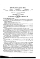
`Be it known thatrI, JOHN S.; HALL, of Pittsburg, in the county of Allegheny, and State of Pennsylvania, have invented .a new and useful Improvement in Nut-Machines; and I do hereby declare that the following is a. full, clear, and exact descriptionthereof, reference being had tothe accompanying drawings, in which- Figure I is a side elevation'. v
'Figure 2 is a vertical section, taken in the line 'x a: of g. 3.
Thenature of my invention consists in the peculiar arrangement ofthe mechanism of a nut-machine, by which means Athe nut is made by blows, 'instead of positive limitedpressure.
By the latter means, if the piece of iron betoo thick, the machine is liable to break,'or if' the viron be too thin, an imperfect nut is made, but by my arrangement this difficulty is obviated.
To'enable others skilled in the'art to make and use my invention, I will proceed. to describe itsconstruction and operation.'
In the drawings, the nachine is represented as in the position when about to make the nut.
A represents the frame of the machine; B, the box, in which the ram C slides;` C, the ram, in which the punch D is firmly held; E, the ram, in which the 4punch F is firmly held; Il', the punch, by which the hole in the nut is made; G, the die, in which the -nut is held while being punched; H, the box, in which the die Gis held; I, the follower; J,-the holder, in which the follower is secured; K; the guide-box, in which'the holder J. works; L, the driving-head, which is connected' to the holder J by .means of rods or bars a.
In the lower part of the driving-head L, one end of the eccentric-lever M is secured. rlhis driving-head `works on a bolt, b, which passes throngh'the journal-boxes N, on the end of the frame A. The lever M extends the length of the machine, and is operated by a cam, O, on lthe shaft c.' Nearthe centre of the leverM is a slot,'d, in which is a crank, P. To the orankLshaft'is attached aweghted lever, Q.
R R representhalf-toggles, one end of each 'being pivoted to the punch-holder C, and the other ends'a're pivoted to the ears underthe shaft of the driving-head S.
'l represents a half toggle, one end of which is pivoted to the ram E, and the other end to the ear on the under side ofthe shaft ofthe driving-head- U. The shafts ofthe driving-heads S U are journalled tothe frame A. i I
Inthe driving-heads SU are secured drop-lerers V W, on the outer ends of which are weights V W. The lever V is operated by the cam X, and the lever W by the cam Y, the three cams O X Y being upon one shaft.
The operation of the machine is as follows:
The hot bar of iron is placed between the faces of the die G and the end of the punch D, as seen in g. 2, itsend being against the adjustable stop e. The power maybe applied, through the shaft c, by any method.
In the drawings, `'the levers V W are represented as resting on the outer edges of the cams X Y. As the cams revolve, when the end of the cam X passes beyond the end, of the weighted drop-lever V, the said lever falls, thereby givinga partial revolution to the shaft of the driving-head S, which, by ineans ofthe half toggles R R, drivesthe ram (land the punch D against the bar of iron, clitting it oi and driving it into the b'ar Gr.
By this timethe end ofthe cam Y has reached the end' of the drop-lever W, ,which falls,.an d gives a' partial revolution to the shaft of the driving-head U, operates the half toggle T, forces the rain E and punch F forward,
and punches the hole in the nut,` the pieces punched from the blank passing out through the opening in the follower I and holder J.
When the nut is punched, the punchesDand F recede, and the cam O strikes the end of the lever M, forcing it down, which gives a forward movement to the follower I, and thus forces out the nut from the inside of the die and it then falls through the opening f in the frameA.`
After the cam O has released the lever 'M from pressure, the said lever is thrown back into its former position, by means of the weighted lever Q, which raises the crank P, which passes through the slot al in the lever M. This completes the'operation, and the machine is in position to repeat its former operation.
Having thus fully described my invention', what I claim, and desire to secure by Letters Patent, is
1. The arrangement of the heling-punch F, cutting-out swagng-punch D, ram C, and half toggies R R, T, with the weighted levers V W, al1 constructed andoperated substantially in the manner described.
2. The arrangement of the perforated foilower I, matrix-box H, and holder J, with slotted lever M and weighted crank-lever P Q, the ivhole constructed and operated as herein shown and described. y
3. The improved machine, as described and shown,`for making nuts from`hot bars of iron, in the manner specified.
I JOHN S. HALL.
Witnesses G. W. WARREN, EDM. F. BROWN.
Publications (1)
| Publication Number | Publication Date |
|---|---|
| US80946A true US80946A (en) | 1868-08-11 |
Family
ID=2150441
Family Applications (1)
| Application Number | Title | Priority Date | Filing Date |
|---|---|---|---|
| US80946D Expired - Lifetime US80946A (en) | John s |
Country Status (1)
| Country | Link |
|---|---|
| US (1) | US80946A (en) |
-
0
- US US80946D patent/US80946A/en not_active Expired - Lifetime
Similar Documents
| Publication | Publication Date | Title |
|---|---|---|
| US80946A (en) | John s | |
| US383200A (en) | Territory | |
| US41861A (en) | Improvement in apparatus for punching and shearing | |
| US75221A (en) | Improved machine foe heading bolts | |
| US53782A (en) | Improvement in nut-machines | |
| US43521A (en) | Improved bolt-heading machine | |
| US49902A (en) | The graphic co | |
| US71181A (en) | Compound tool foe cutting | |
| US46370A (en) | mabbett | |
| US70363A (en) | John root | |
| US53807A (en) | Improvement in machines for making eyelets | |
| US83745A (en) | Island | |
| US36041A (en) | Improvement in machines for making horseshoes | |
| US78576A (en) | Necticut | |
| US82591A (en) | Improved machine | |
| US42608A (en) | Improved machinery for forming hoop-skirt clasps | |
| US51872A (en) | Machine for upsetting wagon-tires | |
| US115868A (en) | Improvement in combined machines for cutting, punching, and bending tires | |
| USRE2434E (en) | William e | |
| US54997A (en) | Improved punching-machine | |
| US114385A (en) | Improvement in machines for shearing metals | |
| US79637A (en) | peters | |
| US207367A (en) | Improvement | |
| US72152A (en) | Abram alexander | |
| US320258A (en) | Horseshoe-bender |