US809463A - Filter. - Google Patents
Filter. Download PDFInfo
- Publication number
- US809463A US809463A US15889503A US1903158895A US809463A US 809463 A US809463 A US 809463A US 15889503 A US15889503 A US 15889503A US 1903158895 A US1903158895 A US 1903158895A US 809463 A US809463 A US 809463A
- Authority
- US
- United States
- Prior art keywords
- casing
- partition
- filter
- openings
- covers
- Prior art date
- Legal status (The legal status is an assumption and is not a legal conclusion. Google has not performed a legal analysis and makes no representation as to the accuracy of the status listed.)
- Expired - Lifetime
Links
- 238000005192 partition Methods 0.000 description 84
- 239000000463 material Substances 0.000 description 37
- 238000001914 filtration Methods 0.000 description 29
- 239000012530 fluid Substances 0.000 description 14
- 238000012856 packing Methods 0.000 description 14
- XLYOFNOQVPJJNP-UHFFFAOYSA-N water Substances O XLYOFNOQVPJJNP-UHFFFAOYSA-N 0.000 description 14
- 239000011521 glass Substances 0.000 description 10
- 239000007788 liquid Substances 0.000 description 6
- 238000010276 construction Methods 0.000 description 4
- 238000005266 casting Methods 0.000 description 2
- 239000008187 granular material Substances 0.000 description 2
- 239000008213 purified water Substances 0.000 description 2
- 239000004576 sand Substances 0.000 description 2
- 239000002699 waste material Substances 0.000 description 2
- FGRBYDKOBBBPOI-UHFFFAOYSA-N 10,10-dioxo-2-[4-(N-phenylanilino)phenyl]thioxanthen-9-one Chemical compound O=C1c2ccccc2S(=O)(=O)c2ccc(cc12)-c1ccc(cc1)N(c1ccccc1)c1ccccc1 FGRBYDKOBBBPOI-UHFFFAOYSA-N 0.000 description 1
- 230000004308 accommodation Effects 0.000 description 1
- 238000004140 cleaning Methods 0.000 description 1
- 230000003292 diminished effect Effects 0.000 description 1
- 239000012535 impurity Substances 0.000 description 1
- 238000007689 inspection Methods 0.000 description 1
- 238000004519 manufacturing process Methods 0.000 description 1
- 239000002245 particle Substances 0.000 description 1
- 229920000136 polysorbate Polymers 0.000 description 1
- 238000009877 rendering Methods 0.000 description 1
- 230000000717 retained effect Effects 0.000 description 1
- 239000012780 transparent material Substances 0.000 description 1
Images


Classifications
-
- B—PERFORMING OPERATIONS; TRANSPORTING
- B01—PHYSICAL OR CHEMICAL PROCESSES OR APPARATUS IN GENERAL
- B01D—SEPARATION
- B01D21/00—Separation of suspended solid particles from liquids by sedimentation
- B01D21/02—Settling tanks with single outlets for the separated liquid
Definitions
- WOIIOIQIVVIIIJIIIQM 5 had-66a;
- My invention consists of an improved device primarily designed for removing impurities from water, the main object of the invention being to provide a filter which while efficiently performing the functions for which it is designed shall in addition be simple to construct, easy to maintain in operative condition, and at the same time occupy but relatively little space for a given capacity.
- a further object of the invention is to provide a filter of such a construction that it shall be possible to conveniently ascertain the condition of certain portions of its interior while it is in operation.
- Figure 1 is a side elevation of my improved filter, showing the piping connections therefor.
- Fig. 2 is a plan view of the filter.
- Fig. 3 is a sectional elevation, illustrating the detail construction of' the interior of my improved filter.
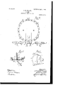
- Fig. 4 is an enlarged sectional elevation of one of the perforated covers employed in the lower portion of my improved filter, as shown in Fig. 3.
- Fig. 5 is a sectional plan view, somewhat enlarged, show- I ing the detail construction of the joint be tween the observation-glass and the filtercasing; and
- Fig. 6 is an elevation showing the detail. construction of the observationglass holder and the mirror therefor.
- the filter-casing proper consists of two cylindrical castings A and A, united to each other by bolts connecting suitable flanged portions, the upper of these castings being provided with a head A and the second with a head A
- the head A has a vertical partition a extending across it in such manner as to divide it into two substantially equal chambers, there being in the portion A a second partition 0/, which divides it also into two chambers and which is recessed alongits top surface for the reception of the lower edge of the partition a.
- This edge is preferably made joint, but will be capable of crowding outwardly said packing, so as to permit the flanges of the sections A and A drawn together.
- a convex partition o in which are a number of preferably circular openings, around each of which is an annular recess, as shown in Fig. 4, both in the upper and lower surface of the partition.
- the head has an annular surface for the reception of the body of packing, and the edge of the partition is beveled, so that the innermost portion of it engages the packing before the outer portion, thus tending to crowd said packing outwardly against the walls of the head.
- Semispherical perforated covers'b are designed to fit over the openings and be held in place in the abovementioned annular grooves or recesses by means of bolts 1), which extend through the openings in the partition-head a and engage the pairs'of covers, so as to firmly confine them in position. Rings of packing are placed within each of the annular grooves, so that a tight joint may be made between the covers and the partition.
- two pipes c and 0 enter the upper portion of the casing proper through suitably-formed bosses c 9 one pipe entering the filter-casing at one side of the partition a and the other on the other side of said partition.
- a pipe c is connected to any suitable source of water-supply and to each of the pipes c and c, it being extended beyond them by means of a section 0 which finally enters a pipe 0 connected to the waste.
- a second pipe 0 unites the two pipes c and c to the supplypipe 0 and I preferably interpose a valve (1 at some point in the length of said pipe 0 I similarly provide a valve d in the connection between the pipe 0 and the point of junction of the two pipes c and 0 also placing a valve (1 in the connection between the pipes c and the point of junction of the pipes c and 0 If desired, a valve (1 may be placed at any desired point of the pipe 0 and there should also be placed valves 66 and d in the pipes c and 0, respectively.
- the cylinder casing is filled with a body of sand or other filtering medium, as shown in Fig. 3, which rests upon the partition a and fills the casing to within a relatively short distance of its top.
- a body of sand or other filtering medium as shown in Fig. 3, which rests upon the partition a and fills the casing to within a relatively short distance of its top.
- I form an opening in the filter-casing in such position that it is bisected by the partition a, as clearly shown in Figs. 3 and 5, covering said opening with a plate of glass E and retaining said plate in position by means of a frame a, provided with lugs e for the accommodation of bolts by which said frame and the glass plate may be held to the side of the casing.
- Suitable gaskets e are provided between the plate E and the filter-casing on one side and the plate and the frame 6 on the other side, so as to prevent breakage of the glass and an uneven tension on the bolts and also to form a water-tight joint with the casing. I also preferably place a gasket e between the glass 'plate and the partition 0,. To the frame 6 I hinge a mirror-frame e", in which is supported a mirror 0 silvered on both sides and provided with an opening a through said silvered portion. As shown in Fig.
- the frame a is hinged to the frame 6, so that it may be caused to reflect light into the interior of the filter-casing upon either side of the partition a, being hung so as to be movable on a vertical aXis passing through or parallel with the center of the circular opening in the casing.
- feet F for supporting the filter-casing above the level of the ground and also provide cocks a through which air collecting in the top of the said casing may be permitted to escape.
- valves d and d In operating the device to supply purified water through the pipe 0 the valves d and d are shut,while the valves (1 and d are opened, as is also the valve d, placed in the length of the pipe 0 between its point of junction with the pipe 0 and the pipe 0 Under such conditions water flows through the pipe 0 passes into the filter-casing through the pipes c and 0 into the chambers formed by the partitions a and a and flows down through the body of filtering material B, through the material 12 contained in the covers (i, into the space between the partition a and the bottom of the head A and finally passes out through the pipes c and 0 the valve (1, and pipes", the valve (1 being opened for this pur ose,while the valve d is closed.
- valves (1, d, and d are closed and the valves (1 and d are opened, water from the source of supply then passing from the pipe 0 into the pipes 0 and c to the pipe 0 and into the bottom of the filter-casing, after which it rises through the body of material B.
- valves 01, 1 and d are closed, while the others are opened, with the result that water passes from the source of supply into the filter through both branch pipes c and c and fiows to waste pipe 0 through pipe 0 such flow being allowed until the outfiowing water is perfectly clear, when valves (1 and d are opened and valve 61 is closed.
- the body of relatively coarse sharp gravel placed in the covers not only serves to prevent the filtering material B from passing into the bottom of the head A but also by its movement as occasioned by the flow of water through said covers automatically keeps clean and free from stoppage the perforations through the same.
- the mirror 6 In using the mirror 6 it is preferably turned on its hinge at an angle to the glass plate E and a light held between it and said plate, so that the rays from the light are strongly thrown into the interior of the filter-casing, and the condition of the material therein may be ascertained by looking through the small hole 6 in the mirror. If it is desired to look into the other side of the filter-casing, the mirror-frame is swung on its hinges and the position of the source of light changed so that rays of light may be thrown as desired.
- a filter consisting of a casing containing filtering material, said casing including a portion having a partition extending across it and a head also having a partition placed to form a continuation of the partition in the first portion, said casing being provided with an inlet and anoutlet for liquid to be filtered substantially as described.
- a filter-casing, .containing filtering material having a head with a vertical partition extending across the same and a body portion to said casing having a partition formed in continuation of the partition in the head, with means for forming a joint between said two partitions, said casing being provided with an inlet and an outlet for liquid to be filtered substantially as described.
- a filter consisting of a casing containing filtering material including a substantially cylindrical section or sections and a head,- section, one of the cylindrical sections having a vertical partition extending across it and the head section also having a partition formed in continuation of the first partition, said casing being provided with an inlet and an outlet for liquid to be filtered substantially as described.
- a casing for a filter the same containing filtering material consisting of two sections each having a partition, one of said partitions being formed with a recess for the reception of the end of the other partition so as to form a'substantially continuous surface therewith, said casing being provided with an inlet and an outlet for liquid to be filtered substantially as described.
- a filter-casing containing filtering material said casing including two sections each having a partition, one of said partitions being formed with a recess and the end of the other partition being tapered and adapted to.
- Afilter having openings for the entrance and exit of fluid and including a plurality of sections, certain-of the same having partitions provided with means for forming a relatively tight oint between them, with filtering material filling the same below the portions having the partitions and partially filltending into the portions of the filter on' both sides of the partitions, substantially as described.
- a casing for a filter including sections having partitions extending across them in substantially the same plane, the end of one of the partitions being enlarged and recessed, packing in said recess, said enlarged end being placed to receive the end of the partition of the other section, said end of the other section being sharpened along the edge contacting with the packing, said casing being provided with an inlet and an outlet for liquid to be filtered substantially as described.
- a filter-casing having a partition in its lower portion, said partition having an opening or a series of openings through it with a plurality of perforated covers for each of said openings, the covers being formed of curved material and one of the same having a portion extending above the partition and the otherv projecting below said partition, said casing containing filtering material and being provided with openings for the entrance and exit of fluid treated, substantially as described.
- a casing having a partition extending across it, said partition being provided with ter thereof, openings through said partition, 6 5
- openings each of which is surrounded by annular recesses in both the upper and lower faces of the partition, with two perforated covers for each opening, said covers having portions entering the recesses and means for holding the covers in position, said casing containing filtering material and being provided with openings for the entrance and exit of fluid treated, substantially as described.
- a casing having a partition extending across it, said partition having a series of openings, each of which is surrounded by annular recesses, there being a recess in the upper and one in the lower face of the partition, two perforated covers for each opening, each extending into one of the recesses and projecting from opposite sides of the partition, and a bolt for connecting said covers, said casing containing filtering material and being provided with openings for the entrance "'arrdexifof fluid treated, substantially as described.
- a filter in a filter, the combination of a casing, having openings for the entrance and exit of fluid treated, a partition having a series of openings and extending across the lower portion of the casing, a pair of perforated covers of curved material projecting beyond the surface of the partition for each opening, one projecting above and the other below said partition, means for holding said covers in position and granular material confined between each pair of said covers, substantially as described.
- a filter in a filter, the combination of a casing, having openings for the entrance and exit of fluid treated, a partition extending across said casing and provided with openings, a pair of similar perforated covers for each of the openings projecting from opposite faces of the partition, means for holding said covers in position, means for making a tight joint between the edges of the covers and the partition, and granular material between each pair of covers, substantially as described.
- a filter-casing consisting of a plurality of sections, one of said sections having a sur face for the reception of a ring of packing, a partition extending across the casing, packing on said surface for engagement by the edge of the partition, said edge being formed to force the packing outwardly from the cenperforated covers for said openings and a body of filtering material carried upon said partition, said casing having openings for the entrance and exit of fluid substantially as described.
- a filter-casing having a verticallyplaced partition extending across it and provided with an opening in its wall extending on both sides of said partition, filtering material in the casing with a plate of transparent material covering said opening and means for forming a tight joint between itself and the edge of the partition and the side of the casing, said casing having openings for the entrance and exit of fluids under treatment substantially as described.
- a filter-casing having a'partition extending across its upper portion and provided with an opening extending on both sides of said partition, filtering material in the casing, a plate of glass closing said opening, with means for projecting light into the casing, said casing having openings for the entrance and exit of fluids under treatment substantially as described.
- a filter-casing having a partition extending across its upper portion and provided with an opening extending on both sides of said partition, filtering material in the casing, a plate of glass closing said opening, and a mirror supported so as to be capable of projecting light into the casing on either side of the partition, said casing having openings for the entrance and exit of fluids under treatment substantially as described.
- a filter-casing having a partition extending across its upper portion and provided with an opening extending on both sides of said partition, filtering material in the casing, a plate of glass closing said opening, and a mirror hinged to the casing so as to be free to swing in a position which will make it possible to project light into the easing on either side of the partition, said casing having openings for the entrance and exit of fluids under treatment substantially as described.
- a casing having a partition extending across it, and provided with an opening ex tending on both sides of the partition, filtering material in the casing, a plate of glass closing said opening, and packing between the wall of the casing and the plate and between the edge of the partition and the plate with means for retaining said plate in position, said casing having openings for the entrance and exit of fluids under treatment substantially as described.
- a casing having a partition extending vertically across it and provided with an opening extending on either side of said partition, filtering material in the casing, a plate
- a partition extending vertically across it and provided with an opening extending on either side of said partition, filtering material in the casing, a plate
Landscapes
- Chemical & Material Sciences (AREA)
- Chemical Kinetics & Catalysis (AREA)
- Filtration Of Liquid (AREA)
Description
No. 809,463. PATENTEDJAN. 9, 1906.
- E. W. ROBERTS.
FILTER.
APPLIGATION FILED MAY 26, 1903.
3 SHEETS-SHEET l.
JJLmrnn m1 \LULLAI PATENTED JAN. 9, 1906. E. W. ROBERTS.
FILTER.
APPLICATION FILED MAY 26, 1903.
3 SHEETS-SHEHT 2.
[ZUWLZEFL l YZwooaZ/V 7805012239,
WOIIOIQIVVIIIJIIIQM 5 had-66a;
PATBNTED JAN. 9, 1906,
E, W. ROBERTS.
FILTER.
nnmumx FILED um 26 s sums-sum '3.-
UNITED STATES ELLwoon W. ROBERTS, or
PATENT OFFICE.-
PHILADELPHIA, PENNSYLVANIA, ASSIGNOR,
BY MESNE ASSIGNMENTS, TO ROBERTS MANUFACTURING COMPANY, INCORPORATED, A CORPORATION OF NEW J ERSEY FILTER.
Patented Jan. 9, 1906.
$0 aZZ whmn it warty concern:
Be it known that I, ELLwooD W. Ron- ERTS, a citizen of-the United States, residing in Philadelphia, Pennsylvania, have invented certain Improvements in Filters, of which the following is a specification.
My invention consists of an improved device primarily designed for removing impurities from water, the main object of the invention being to provide a filter which while efficiently performing the functions for which it is designed shall in addition be simple to construct, easy to maintain in operative condition, and at the same time occupy but relatively little space for a given capacity.
A further object of the invention is to provide a filter of such a construction that it shall be possible to conveniently ascertain the condition of certain portions of its interior while it is in operation.
The above objects I attain as hereinafter set forth, reference being had to the accompanying drawings, in which Figure 1 is a side elevation of my improved filter, showing the piping connections therefor. Fig. 2 is a plan view of the filter. Fig. 3 is a sectional elevation, illustrating the detail construction of' the interior of my improved filter. Fig. 4 is an enlarged sectional elevation of one of the perforated covers employed in the lower portion of my improved filter, as shown in Fig. 3. Fig. 5 is a sectional plan view, somewhat enlarged, show- I ing the detail construction of the joint be tween the observation-glass and the filtercasing; and Fig. 6 is an elevation showing the detail. construction of the observationglass holder and the mirror therefor.
In the above drawings it is seen that the filter-casing proper consists of two cylindrical castings A and A, united to each other by bolts connecting suitable flanged portions, the upper of these castings being provided with a head A and the second with a head A The head A has a vertical partition a extending across it in such manner as to divide it into two substantially equal chambers, there being in the portion A a second partition 0/, which divides it also into two chambers and which is recessed alongits top surface for the reception of the lower edge of the partition a. This edge is preferably made joint, but will be capable of crowding outwardly said packing, so as to permit the flanges of the sections A and A drawn together.
. Near the bottom of the casing proper and extending across the head A is a convex partition o in which are a number of preferably circular openings, around each of which is an annular recess, as shown in Fig. 4, both in the upper and lower surface of the partition. As shown in Fig. 3, the head has an annular surface for the reception of the body of packing, and the edge of the partition is beveled, so that the innermost portion of it engages the packing before the outer portion, thus tending to crowd said packing outwardly against the walls of the head. Semispherical perforated covers'b are designed to fit over the openings and be held in place in the abovementioned annular grooves or recesses by means of bolts 1), which extend through the openings in the partition-head a and engage the pairs'of covers, so as to firmly confine them in position. Rings of packing are placed within each of the annular grooves, so that a tight joint may be made between the covers and the partition.
I preferably place within each of the inclosures formed of the covers I) a mass of relatively coarse sand or gravel b the same being composed of particles larger than the perforations in the heads.
As shown in Figs. 1 and 2, two pipes c and 0 enter the upper portion of the casing proper through suitably-formed bosses c 9 one pipe entering the filter-casing at one side of the partition a and the other on the other side of said partition. A pipe c is connected to any suitable source of water-supply and to each of the pipes c and c, it being extended beyond them by means of a section 0 which finally enters a pipe 0 connected to the waste.
There is an opening into the head A near the bottom of the filter-casing through a pipe whose end is shown at c, which pipe is connected, by means of a section 0 to the waste-pipe c and by means of a section 0 to a pipe 0 leading to a tank or to a distributing to be tightly system for purified water. A second pipe 0 unites the two pipes c and c to the supplypipe 0 and I preferably interpose a valve (1 at some point in the length of said pipe 0 I similarly provide a valve d in the connection between the pipe 0 and the point of junction of the two pipes c and 0 also placing a valve (1 in the connection between the pipes c and the point of junction of the pipes c and 0 If desired, a valve (1 may be placed at any desired point of the pipe 0 and there should also be placed valves 66 and d in the pipes c and 0, respectively.
Under operating conditions the cylinder casing is filled with a body of sand or other filtering medium, as shown in Fig. 3, which rests upon the partition a and fills the casing to within a relatively short distance of its top. At a point approximately on a level with the top surface of this body of filtering material I form an opening in the filter-casing in such position that it is bisected by the partition a, as clearly shown in Figs. 3 and 5, covering said opening with a plate of glass E and retaining said plate in position by means of a frame a, provided with lugs e for the accommodation of bolts by which said frame and the glass plate may be held to the side of the casing. Suitable gaskets e are provided between the plate E and the filter-casing on one side and the plate and the frame 6 on the other side, so as to prevent breakage of the glass and an uneven tension on the bolts and also to form a water-tight joint with the casing. I also preferably place a gasket e between the glass 'plate and the partition 0,. To the frame 6 I hinge a mirror-frame e", in which is supported a mirror 0 silvered on both sides and provided with an opening a through said silvered portion. As shown in Fig. 6, the frame a is hinged to the frame 6, so that it may be caused to reflect light into the interior of the filter-casing upon either side of the partition a, being hung so as to be movable on a vertical aXis passing through or parallel with the center of the circular opening in the casing.
In the device illustrated I provide feet F for supporting the filter-casing above the level of the ground and also provide cocks a through which air collecting in the top of the said casing may be permitted to escape.
In operating the device to supply purified water through the pipe 0 the valves d and d are shut,while the valves (1 and d are opened, as is also the valve d, placed in the length of the pipe 0 between its point of junction with the pipe 0 and the pipe 0 Under such conditions water flows through the pipe 0 passes into the filter-casing through the pipes c and 0 into the chambers formed by the partitions a and a and flows down through the body of filtering material B, through the material 12 contained in the covers (i, into the space between the partition a and the bottom of the head A and finally passes out through the pipes c and 0 the valve (1, and pipes", the valve (1 being opened for this pur ose,while the valve d is closed. When the filter ceases to operate properly, or when the quantity of water delivered in any given time has become diminished to a predetermined extent, as caused by the collection of foreign matter upon the upper surface of the body of filtering material B, I close the valve 61 and proceed to clean the filter. By the proper use of the mirror 6 li ht may be reflected into the interior of the filter-casing, so as to show the condition of'the top surface of the body of filtering material, thus rendering it possible to ascertain at a glance whether the filter is in proper working condition.
In cleaning the filter the valves (1, d, and d are closed and the valves (1 and d are opened, water from the source of supply then passing from the pipe 0 into the pipes 0 and c to the pipe 0 and into the bottom of the filter-casing, after which it rises through the body of material B. Since there is no escape for it from that part of the casing in communication with the pipe 0, all of the infiowing water is caused to pass through the body of filtering material in the chamber formed by the partitions a and a and in communication with the pipe 0, and it will therefore be noted that the whole volume of infiowing water is directed through a relatively small body of said material, so that said body is in a relatively short time thoroughly washed, the dirty water carrying the foreign material passing out through the pipe 0 into the pipe 0 through the valve d and out through the waste-pipe (i When this portion of the filtering material in the casing has been thoroughly cleansed, as may be determined by inspection through the glass-covered opening in the side of the casing, the valve d is shut and the valve (1 is opened, thereby forcing the body of water flowing through the filter to pass through and cleanse the body of material contained in the second chamber, formed by the partitions a and a. After all the filtering material has been thoroughly washed, as above described, valves 01, 1 and d are closed, while the others are opened, with the result that water passes from the source of supply into the filter through both branch pipes c and c and fiows to waste pipe 0 through pipe 0 such flow being allowed until the outfiowing water is perfectly clear, when valves (1 and d are opened and valve 61 is closed.
It will be noted that in constructing my improved filter I preferably employ pipes of the same diameter throughout, so that the water flowing in through the pipes is delivered at full pressure to either of the relatively small volumes of filtering material contained in the chambers formed by the partitions a and a.
The body of relatively coarse sharp gravel placed in the covers not only serves to prevent the filtering material B from passing into the bottom of the head A but also by its movement as occasioned by the flow of water through said covers automatically keeps clean and free from stoppage the perforations through the same.
In using the mirror 6 it is preferably turned on its hinge at an angle to the glass plate E and a light held between it and said plate, so that the rays from the light are strongly thrown into the interior of the filter-casing, and the condition of the material therein may be ascertained by looking through the small hole 6 in the mirror. If it is desired to look into the other side of the filter-casing, the mirror-frame is swung on its hinges and the position of the source of light changed so that rays of light may be thrown as desired.
I claim as my invention 1. A filter consisting of a casing containing filtering material, said casing including a portion having a partition extending across it and a head also having a partition placed to form a continuation of the partition in the first portion, said casing being provided with an inlet and anoutlet for liquid to be filtered substantially as described.
2. A filter-casing, .containing filtering material having a head with a vertical partition extending across the same and a body portion to said casing having a partition formed in continuation of the partition in the head, with means for forming a joint between said two partitions, said casing being provided with an inlet and an outlet for liquid to be filtered substantially as described.
3. A filter consisting of a casing containing filtering material including a substantially cylindrical section or sections and a head,- section, one of the cylindrical sections having a vertical partition extending across it and the head section also having a partition formed in continuation of the first partition, said casing being provided with an inlet and an outlet for liquid to be filtered substantially as described.
4. A casing for a filter, the same containing filtering material consisting of two sections each having a partition, one of said partitions being formed with a recess for the reception of the end of the other partition so as to form a'substantially continuous surface therewith, said casing being provided with an inlet and an outlet for liquid to be filtered substantially as described.-
5. A filter-casing containing filtering material, said casing including two sections each having a partition, one of said partitions being formed with a recess and the end of the other partition being tapered and adapted to.
enter the recess, with packing for said recess, said casing being provided with an inlet and an outlet for liquid to be filtered substantially as described.
6. Afilterhaving openings for the entrance and exit of fluid and including a plurality of sections, certain-of the same having partitions provided with means for forming a relatively tight oint between them, with filtering material filling the same below the portions having the partitions and partially filltending into the portions of the filter on' both sides of the partitions, substantially as described.
8. A casing for a filter, the same containing filtering material, including sections having partitions extending across them in substantially the same plane, the end of one of the partitions being enlarged and recessed, packing in said recess, said enlarged end being placed to receive the end of the partition of the other section, said end of the other section being sharpened along the edge contacting with the packing, said casing being provided with an inlet and an outlet for liquid to be filtered substantially as described.
9. A filter-casing having a partition in its lower portion provided with filtering material, said partition having an opening or series of openings through it with a plurality of perforated covers for each of said openings, each of said covers coacting with the other so that said covers are retained in position over the openings, said covers being of material curved to project beyond the surface of the partition, said casing having openings for the entrance and exit of fluid treated, substantially as described.
10. A filter-casing having a partition in its lower portion, said partition having an opening or a series of openings through it with a plurality of perforated covers for each of said openings, the covers being formed of curved material and one of the same having a portion extending above the partition and the otherv projecting below said partition, said casing containing filtering material and being provided with openings for the entrance and exit of fluid treated, substantially as described.
11. A casing having a partition extending across it, said partition being provided with ter thereof, openings through said partition, 6 5
openings each of which is surrounded by annular recesses in both the upper and lower faces of the partition, with two perforated covers for each opening, said covers having portions entering the recesses and means for holding the covers in position, said casing containing filtering material and being provided with openings for the entrance and exit of fluid treated, substantially as described.
12. A casing having a partition extending across it, said partition having a series of openings, each of which is surrounded by annular recesses, there being a recess in the upper and one in the lower face of the partition, two perforated covers for each opening, each extending into one of the recesses and projecting from opposite sides of the partition, and a bolt for connecting said covers, said casing containing filtering material and being provided with openings for the entrance "'arrdexifof fluid treated, substantially as described.
13. In a filter, the combination of a casing, having openings for the entrance and exit of fluid treated, a partition having a series of openings and extending across the lower portion of the casing, a pair of perforated covers of curved material projecting beyond the surface of the partition for each opening, one projecting above and the other below said partition, means for holding said covers in position and granular material confined between each pair of said covers, substantially as described.
14. In a filter, the combination of a casing, having openings for the entrance and exit of fluid treated, a partition extending across said casing and provided with openings, a pair of similar perforated covers for each of the openings projecting from opposite faces of the partition, means for holding said covers in position, means for making a tight joint between the edges of the covers and the partition, and granular material between each pair of covers, substantially as described.
15. A filter-casing containing filtering material in combination with a perforated partition across the same, said casing having a surface for the reception of the said partition, packing between the said surface and the partition, the edge of the partition being beveled so that the portion thereof nearest the center engages the packing before the portion farther from said center, said casing having openings for the entrance and exit of fluid substantially as described.
16. A filter-casing consisting of a plurality of sections, one of said sections having a sur face for the reception of a ring of packing, a partition extending across the casing, packing on said surface for engagement by the edge of the partition, said edge being formed to force the packing outwardly from the cenperforated covers for said openings and a body of filtering material carried upon said partition, said casing having openings for the entrance and exit of fluid substantially as described.
17. A filter-casing having a verticallyplaced partition extending across it and provided with an opening in its wall extending on both sides of said partition, filtering material in the casing with a plate of transparent material covering said opening and means for forming a tight joint between itself and the edge of the partition and the side of the casing, said casing having openings for the entrance and exit of fluids under treatment substantially as described.
18. A filter-casing having a'partition extending across its upper portion and provided with an opening extending on both sides of said partition, filtering material in the casing, a plate of glass closing said opening, with means for projecting light into the casing, said casing having openings for the entrance and exit of fluids under treatment substantially as described.
19. A filter-casing having a partition extending across its upper portion and provided with an opening extending on both sides of said partition, filtering material in the casing, a plate of glass closing said opening, and a mirror supported so as to be capable of projecting light into the casing on either side of the partition, said casing having openings for the entrance and exit of fluids under treatment substantially as described.
20. A filter-casing having a partition extending across its upper portion and provided with an opening extending on both sides of said partition, filtering material in the casing, a plate of glass closing said opening, and a mirror hinged to the casing so as to be free to swing in a position which will make it possible to project light into the easing on either side of the partition, said casing having openings for the entrance and exit of fluids under treatment substantially as described.
21. A casing having a partition extending across it, and provided with an opening ex tending on both sides of the partition, filtering material in the casing, a plate of glass closing said opening, and packing between the wall of the casing and the plate and between the edge of the partition and the plate with means for retaining said plate in position, said casing having openings for the entrance and exit of fluids under treatment substantially as described.
22. A casing having a partition extending vertically across it and provided with an opening extending on either side of said partition, filtering material in the casing, a plate In testimony whereof I have signed my name to this specification the presence of 10 two subscribing Witnesses.
ELLWOOD W. ROBERTS Witnesses:
WILLIAM E. BRADLEY, Jos. H. KLEIN.
Priority Applications (1)
| Application Number | Priority Date | Filing Date | Title |
|---|---|---|---|
| US15889503A US809463A (en) | 1903-05-26 | 1903-05-26 | Filter. |
Applications Claiming Priority (1)
| Application Number | Priority Date | Filing Date | Title |
|---|---|---|---|
| US15889503A US809463A (en) | 1903-05-26 | 1903-05-26 | Filter. |
Publications (1)
| Publication Number | Publication Date |
|---|---|
| US809463A true US809463A (en) | 1906-01-09 |
Family
ID=2877944
Family Applications (1)
| Application Number | Title | Priority Date | Filing Date |
|---|---|---|---|
| US15889503A Expired - Lifetime US809463A (en) | 1903-05-26 | 1903-05-26 | Filter. |
Country Status (1)
| Country | Link |
|---|---|
| US (1) | US809463A (en) |
-
1903
- 1903-05-26 US US15889503A patent/US809463A/en not_active Expired - Lifetime
Similar Documents
| Publication | Publication Date | Title |
|---|---|---|
| US1945839A (en) | Filtering apparatus | |
| US1090283A (en) | Water filterer or strainer. | |
| US191131A (en) | Improvement in filtering apparatus | |
| US809463A (en) | Filter. | |
| JPS5950367B2 (en) | filtration device | |
| US3278034A (en) | Filter tank and valve assembly | |
| US607155A (en) | Filter | |
| US651173A (en) | Filter. | |
| US788359A (en) | Water-filter. | |
| US2243949A (en) | Refrigerating circuit purifier | |
| US528652A (en) | Filtering apparatus | |
| US2459353A (en) | Liquid filter | |
| US413671A (en) | jewell | |
| US484781A (en) | Filter | |
| US3369669A (en) | Domestic back flush water system filter | |
| US331790A (en) | Filter | |
| JP4951473B2 (en) | Filtration device | |
| US619838A (en) | Zoroaster f | |
| US264011A (en) | Filter | |
| US791647A (en) | Filtering system. | |
| US1846419A (en) | Automatic water softener | |
| US272596A (en) | Benjamin f | |
| US791213A (en) | Water-filter. | |
| US813517A (en) | Water-filter. | |
| US358107A (en) | Machine |