US809458A - Smoke-consuming furnace. - Google Patents
Smoke-consuming furnace. Download PDFInfo
- Publication number
- US809458A US809458A US1905257394A US809458A US 809458 A US809458 A US 809458A US 1905257394 A US1905257394 A US 1905257394A US 809458 A US809458 A US 809458A
- Authority
- US
- United States
- Prior art keywords
- valve
- furnace
- smoke
- pipe
- furnaces
- Prior art date
- Legal status (The legal status is an assumption and is not a legal conclusion. Google has not performed a legal analysis and makes no representation as to the accuracy of the status listed.)
- Expired - Lifetime
Links
- 239000000779 smoke Substances 0.000 description 8
- 238000010276 construction Methods 0.000 description 3
- 239000000446 fuel Substances 0.000 description 3
- 238000002485 combustion reaction Methods 0.000 description 1
- 230000002939 deleterious effect Effects 0.000 description 1
- 230000003467 diminishing effect Effects 0.000 description 1
- 239000003517 fume Substances 0.000 description 1
- 239000007789 gas Substances 0.000 description 1
- 238000000034 method Methods 0.000 description 1
- 239000000047 product Substances 0.000 description 1
Images

Classifications
-
- B—PERFORMING OPERATIONS; TRANSPORTING
- B01—PHYSICAL OR CHEMICAL PROCESSES OR APPARATUS IN GENERAL
- B01D—SEPARATION
- B01D53/00—Separation of gases or vapours; Recovering vapours of volatile solvents from gases; Chemical or biological purification of waste gases, e.g. engine exhaust gases, smoke, fumes, flue gases, aerosols
- B01D53/02—Separation of gases or vapours; Recovering vapours of volatile solvents from gases; Chemical or biological purification of waste gases, e.g. engine exhaust gases, smoke, fumes, flue gases, aerosols by adsorption, e.g. preparative gas chromatography
- B01D53/06—Separation of gases or vapours; Recovering vapours of volatile solvents from gases; Chemical or biological purification of waste gases, e.g. engine exhaust gases, smoke, fumes, flue gases, aerosols by adsorption, e.g. preparative gas chromatography with moving adsorbents, e.g. rotating beds
- B01D53/10—Separation of gases or vapours; Recovering vapours of volatile solvents from gases; Chemical or biological purification of waste gases, e.g. engine exhaust gases, smoke, fumes, flue gases, aerosols by adsorption, e.g. preparative gas chromatography with moving adsorbents, e.g. rotating beds with dispersed adsorbents
- B01D53/12—Separation of gases or vapours; Recovering vapours of volatile solvents from gases; Chemical or biological purification of waste gases, e.g. engine exhaust gases, smoke, fumes, flue gases, aerosols by adsorption, e.g. preparative gas chromatography with moving adsorbents, e.g. rotating beds with dispersed adsorbents according to the "fluidised technique"
-
- Y—GENERAL TAGGING OF NEW TECHNOLOGICAL DEVELOPMENTS; GENERAL TAGGING OF CROSS-SECTIONAL TECHNOLOGIES SPANNING OVER SEVERAL SECTIONS OF THE IPC; TECHNICAL SUBJECTS COVERED BY FORMER USPC CROSS-REFERENCE ART COLLECTIONS [XRACs] AND DIGESTS
- Y10—TECHNICAL SUBJECTS COVERED BY FORMER USPC
- Y10T—TECHNICAL SUBJECTS COVERED BY FORMER US CLASSIFICATION
- Y10T137/00—Fluid handling
- Y10T137/8593—Systems
- Y10T137/86493—Multi-way valve unit
- Y10T137/86574—Supply and exhaust
- Y10T137/86638—Rotary valve
- Y10T137/86646—Plug type
- Y10T137/86654—For plural lines
Definitions
- My invention relates to improvements in furnaces, and particularly to that class or construction denominated as smoke-consuming furnaces; and the object is to make a furnace of the kind named which will operate to accomplish the consumption of the smoke products to the extent that no heavy, thick, or dense and black smoke will issue from the stack during the operation of stok ing or charging the furnace, and this I accomplish by the constructions and appliances fully and clearly illustrated in the annexed drawings, and which will hereinafter be described as prescribed and intended by the statute.
- Figure l is a front view in elevation of a furnace adapted to have the improvements connected thereto. This illustration also shows a dial-plate having suitable graduations marked thereon and an arm or pointer turnable with the valve-operating shaft to indicate what drafts are on and what are cut ofi.
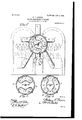
- Fig. 2 is aview in elevation of the rear of the furnace, showing my improved apparatus or device mounted in operative position thereon, the valve or cut-off being shown in transverse section and the valve as being turned in position for carrying the smoke from the lefthand furnace into the right-hand under the grate-bars.
- Fig. 3 is a transverse sectional view through the valve and valve-casing, showing the valve turned to open all the drafts.
- Fig. 1 is a transverse sectional view through the valve and valve-casing, showing the valve turned to open all the drafts.
- FIG. 4 is a transverse sectional view through the valve and valvecasing, showing the valve turned to cut off the lateral pipes and leaving the direct drafts on.
- Fig. 5 is avertical central section through the valve and valve-casing and of the main draft-pipe and the chimney or stack, also showing the shaft for operating the valve from the front of the furnace.
- Fig. 6 is a perspective view of the valve.
- Fig. 7 is a longitudinal vertical section taken through one of the furnaces, indicating the usual draft course, showing the device mounted in position.
- 1 designates the front of the furnace or furnaces, which may be of any approved construction and provided with doors 2, opening into the boiler-space, and other doors 3, leading into the fire-chamber, and doors 4, closing the ash-pit.
- a circular casing 5 having pipe-openings therein, as 6 7 8 9 10 11, the draft-supply pipe 12, opening into the casing through the opening 10, and the opening 7, leading into the stack or chimney 13.
- the opening 6 registers with a pipe 14, opening into the smoke-space of the furnace.
- the opening 8 communicates with a pipe 15, which leads from the smoke-space behind the the furnace.
- the openings 9 and 11 communicate, respectively, with pipes 16 17, which lead into.
- the furnace through the bridge-wall and open under the grate-bars, as indicated in Figs. 2 and 7, being adapted to convey the heavy smoke to delivery under the ate-bars and fire-box;rvhence it is drawn up t ough the fire and consumed;
- valve-casing 5 In the valve-casing 5 is rotatably mounted a valve 18, formed or provided with oppositely positioned chambers 19 20, having rounded end walls and concentric side walls, as shown, the inner edges of the walls being adapted to sweep over the o enings in the back plate of the casing, so tfiat the proper communication between determined or selected pipes may, readily be made.
- the valve-casing 5 is formed with a bearing 21, and the valve is made with a bearing-sleeve 22, wherein is fixed a turning shaft 23, which extends through a bearing 24 in the back wall of the valve-casing and thence to the front of the furnace, and on the projecting end of the shaft is fixedly mounted a sleeve 25, provided with a pointer 26, having a handlepiece 27, whereby the shaft may be turned and the valve operated from the front of the furnace.
- a disk 28 is mounted at the front of the furnace and graduated to indicate the various positions to which the valve must be turned to produce certain prescribed results.
- Fig. 3 is shown the valve in position when it is not consuming smoke during the process of stoking, the draft-tubes being wide open on the furnaces, and in Fig. 4 the side and lateral pipes are cut out and the direct draft effected through pipes 12 and 18 through the valve passage and openings 7 and 10.
- the apparatus or devices are applicable to a plurality of furnaces by extending the pipe arrangement to take in the additional furnaces and, further, that it may be used on a single furnace by moving the valve to take in the downdraft-pipe and opening the direct-draft 1 es.
- the valve is turned to uncover the openingsfi and 9, making a free passa e through the valve from the former into t e latter.
- the valve When the right-hand furnace is to be stoked, the valve is turned to bringthe valvepassage to stand in alinement with the openings 8 and 11, the products of the charged fuel will travel through the furnace, as stated in the aboveFdescribed instance, pass into the smoke-space, through pipe 15, through the valve passage, through opening 11, and thence by the downdraft-pipe 16 under the grate, whence it is burned in passing up through the fire.
- What I claim is 1.
- a smoke-consuming furnace furnaces positioned side by side, a pipe leading from the smoke-space of each furnace, a valve-casing into which said pipes open, a revoluble valve mounted in the casing and formed with oppositely-positioned chambers and a passage between the chambers, downdraft-pipes leading from the valve-casing into the opposite furnaces under the grates thereof, and means to turn the valve to cut off and establish communication between determined pipeopenings in the casing.
Landscapes
- Chemical & Material Sciences (AREA)
- Dispersion Chemistry (AREA)
- Engineering & Computer Science (AREA)
- Analytical Chemistry (AREA)
- General Chemical & Material Sciences (AREA)
- Oil, Petroleum & Natural Gas (AREA)
- Chemical Kinetics & Catalysis (AREA)
- Feeding And Controlling Fuel (AREA)
Description
No. 809,458. PATENTED JAN. 9, 1906.
, W. T. PAXSON. SMOKE GONSUMING FURNACE.
APPLICATION FILED APR. 25, 1905.
3 SHEETS-SHB ET l.
T0 FIRE THIS 20 1 OOZMCZ, ZIZO lbw-809,458 PATBNTEDJAN.9, 1906.
W. T. PAXSON.
SMOKE GONSUMING FURNACE. APPLICATION FILED APR. 25, 1905.
3 SHEETS-BEBE! 2. F 2 v arwentoz mwm sag,
N0. 809,458. PATENTED JAN. 9, 1906.
W. T. PAXSON.
SMOKE GONSUMING FURNACE. APPLICATION FILED APR. 25, 1905.
a snns rs-snnm 3. I \N 1 nmrnn STATES PATENT OFFICE.
WALLACE T. PAXSON, OF WASHINGTON, DISTRICT OF COLUMBIA, ASSIGNOR, BY DIRECT AND MESNE ASSIGNMENTS, TO JACOB B. MAXWELL, OF WASHINGTON, DISTRICT OF COLUMBIA.
SMOKE-CONSUMING FURNACE.
Patented. Jan. 9, 1906.
Application filed April 25, 1905. Serial No. 257.394.
T aZZ whom, it may concern.-
Be it known that LWALLAOE T. PAXsoN, a citizen of the United States, residing at the city of Washington, in the District of Columbia, have invented new and useful Improvements in Smoke- Consuming Furnaces, of which the following is a specification.
My invention relates to improvements in furnaces, and particularly to that class or construction denominated as smoke-consuming furnaces; and the object is to make a furnace of the kind named which will operate to accomplish the consumption of the smoke products to the extent that no heavy, thick, or dense and black smoke will issue from the stack during the operation of stok ing or charging the furnace, and this I accomplish by the constructions and appliances fully and clearly illustrated in the annexed drawings, and which will hereinafter be described as prescribed and intended by the statute.
In the drawings, Figure l is a front view in elevation of a furnace adapted to have the improvements connected thereto. This illustration also shows a dial-plate having suitable graduations marked thereon and an arm or pointer turnable with the valve-operating shaft to indicate what drafts are on and what are cut ofi. Fig. 2 is aview in elevation of the rear of the furnace, showing my improved apparatus or device mounted in operative position thereon, the valve or cut-off being shown in transverse section and the valve as being turned in position for carrying the smoke from the lefthand furnace into the right-hand under the grate-bars. Fig. 3 is a transverse sectional view through the valve and valve-casing, showing the valve turned to open all the drafts. Fig. 4 is a transverse sectional view through the valve and valvecasing, showing the valve turned to cut off the lateral pipes and leaving the direct drafts on. Fig. 5 is avertical central section through the valve and valve-casing and of the main draft-pipe and the chimney or stack, also showing the shaft for operating the valve from the front of the furnace. Fig. 6 is a perspective view of the valve. Fig. 7 is a longitudinal vertical section taken through one of the furnaces, indicating the usual draft course, showing the device mounted in position.
In the drawings similar parts appearing in different illustrations are designated by the same reference-notations.
Reference being made to the drawings, 1 designates the front of the furnace or furnaces, which may be of any approved construction and provided with doors 2, opening into the boiler-space, and other doors 3, leading into the fire-chamber, and doors 4, closing the ash-pit. To the rear walls of the fur- 'naces is rigidly secured a circular casing 5, having pipe-openings therein, as 6 7 8 9 10 11, the draft-supply pipe 12, opening into the casing through the opening 10, and the opening 7, leading into the stack or chimney 13. The opening 6 registers with a pipe 14, opening into the smoke-space of the furnace. The opening 8 communicates with a pipe 15, which leads from the smoke-space behind the the furnace. The openings 9 and 11 communicate, respectively, with pipes 16 17, which lead into. the furnace through the bridge-wall and open under the grate-bars, as indicated in Figs. 2 and 7, being adapted to convey the heavy smoke to delivery under the ate-bars and fire-box;rvhence it is drawn up t ough the fire and consumed;
In the valve-casing 5 is rotatably mounted a valve 18, formed or provided with oppositely positioned chambers 19 20, having rounded end walls and concentric side walls, as shown, the inner edges of the walls being adapted to sweep over the o enings in the back plate of the casing, so tfiat the proper communication between determined or selected pipes may, readily be made. The valve-casing 5 is formed with a bearing 21, and the valve is made with a bearing-sleeve 22, wherein is fixed a turning shaft 23, which extends through a bearing 24 in the back wall of the valve-casing and thence to the front of the furnace, and on the projecting end of the shaft is fixedly mounted a sleeve 25, provided with a pointer 26, having a handlepiece 27, whereby the shaft may be turned and the valve operated from the front of the furnace. To advise as to the proper disposition of the valve, a disk 28 is mounted at the front of the furnace and graduated to indicate the various positions to which the valve must be turned to produce certain prescribed results.
It will be perceived that the location of the chambers in the valve produce a diametrical passage through the valve, so that the valve may be turned to disclose pipe-ports at each end of the passage, as seen in Figs. 2 and 4 of the drawings.
In Fig. 3 is shown the valve in position when it is not consuming smoke during the process of stoking, the draft-tubes being wide open on the furnaces, and in Fig. 4 the side and lateral pipes are cut out and the direct draft effected through pipes 12 and 18 through the valve passage and openings 7 and 10.
It may be stated, as will be also apparent from the foregoing description, that the apparatus or devices are applicable to a plurality of furnaces by extending the pipe arrangement to take in the additional furnaces and, further, that it may be used on a single furnace by moving the valve to take in the downdraft-pipe and opening the direct-draft 1 es. p To disclose the mode of operation as seen in Fig. 2 and indicated in Fig. 7 of the drawings and stoking the left-hand furnace, the valve is turned to uncover the openingsfi and 9, making a free passa e through the valve from the former into t e latter. Then the fumes, gases, and products of combustion emanating from the fuel will pass through under the boiler to the rear, thence reverse and pass through the boiler into the breastspace at the front, thence upward over the boiler into the smoke-space, thence through the pipe 14 into the valve-passage, through the same, then through the downdraft-pipe 17, up through the fuel in that furnace, where the smoke is burned in its passage and freed from all deleterious characteristics and qualities. When the right-hand furnace is to be stoked, the valve is turned to bringthe valvepassage to stand in alinement with the openings 8 and 11, the products of the charged fuel will travel through the furnace, as stated in the aboveFdescribed instance, pass into the smoke-space, through pipe 15, through the valve passage, through opening 11, and thence by the downdraft-pipe 16 under the grate, whence it is burned in passing up through the fire.
Also in the operation of this device there is no diminishing of the draft while consuming the smoke, and as a fuel-saver it is of the first importance, owing to the fact that nothing escapes to the stack unconsumed.
What I claim is 1. In a smoke-consuming furnace, furnaces positioned side by side, a pipe leading from the smoke-space of each furnace, a valve-casing into which said pipes open, a revoluble valve mounted in the casing and formed with oppositely-positioned chambers and a passage between the chambers, downdraft-pipes leading from the valve-casing into the opposite furnaces under the grates thereof, and means to turn the valve to cut off and establish communication between determined pipeopenings in the casing.
2. The combination with adj acently-positioned furnaces the pipes 14 and 15 leading from the smoke-spaces in the furnaces, the draft- pipes 12, 13, and the downdraft- pipes 16, 17, of an inclosed revoluble valve into which all said pipes open, said valve being adapted to cut off and to establish communication between determined pipe-ports, a shaft to turn the valve and extended to the front of the furnace, an arm on the end of the shaft provided with a handle, and a graduated dial over which the arm turns.
In testimony whereof I affix my signature in presence of two subscribing witnesses.
WALLACE T. PAXSON.a
Witnesses:
EDGAR B. SHERRILL, G. L. BAKER.
Priority Applications (1)
| Application Number | Priority Date | Filing Date | Title |
|---|---|---|---|
| US1905257394 US809458A (en) | 1905-04-25 | 1905-04-25 | Smoke-consuming furnace. |
Applications Claiming Priority (1)
| Application Number | Priority Date | Filing Date | Title |
|---|---|---|---|
| US1905257394 US809458A (en) | 1905-04-25 | 1905-04-25 | Smoke-consuming furnace. |
Publications (1)
| Publication Number | Publication Date |
|---|---|
| US809458A true US809458A (en) | 1906-01-09 |
Family
ID=2877939
Family Applications (1)
| Application Number | Title | Priority Date | Filing Date |
|---|---|---|---|
| US1905257394 Expired - Lifetime US809458A (en) | 1905-04-25 | 1905-04-25 | Smoke-consuming furnace. |
Country Status (1)
| Country | Link |
|---|---|
| US (1) | US809458A (en) |
Cited By (1)
| Publication number | Priority date | Publication date | Assignee | Title |
|---|---|---|---|---|
| US2519574A (en) * | 1944-02-28 | 1950-08-22 | James W F Holl | Rotary fluid valve |
-
1905
- 1905-04-25 US US1905257394 patent/US809458A/en not_active Expired - Lifetime
Cited By (1)
| Publication number | Priority date | Publication date | Assignee | Title |
|---|---|---|---|---|
| US2519574A (en) * | 1944-02-28 | 1950-08-22 | James W F Holl | Rotary fluid valve |
Similar Documents
| Publication | Publication Date | Title |
|---|---|---|
| US809458A (en) | Smoke-consuming furnace. | |
| US659161A (en) | Furnace. | |
| US373502A (en) | Smoke-consuming furnace for steam-generators | |
| US652924A (en) | Smokeless furnace. | |
| US205849A (en) | Improvement in smoke-preventing furnaces | |
| US481831A (en) | Air-supply for boiler-furnaces | |
| US464506A (en) | James d | |
| US836745A (en) | Furnace attachment. | |
| US532578A (en) | Smoke-abating furnace | |
| US526657A (en) | Thomas b | |
| US685870A (en) | Furnace. | |
| US1121508A (en) | Furnace. | |
| US268035A (en) | mcauley | |
| US513641A (en) | Furnace | |
| US460359A (en) | Thk mobrts peters co | |
| US390798A (en) | Smokeless furnace | |
| US374285A (en) | And said eichaed d | |
| US951069A (en) | Steam-boiler furnace. | |
| US690581A (en) | Smoke-consuming furnace. | |
| US630703A (en) | Smoke-consumer. | |
| US672480A (en) | Hot-air furnace. | |
| US821961A (en) | Furnace, &c. | |
| US996249A (en) | Furnace. | |
| US888086A (en) | Steam-boiler furnace. | |
| US546178A (en) | murray |