US809455A - Ammunition-hoisting mechanism. - Google Patents
Ammunition-hoisting mechanism. Download PDFInfo
- Publication number
- US809455A US809455A US22444004A US1904224440A US809455A US 809455 A US809455 A US 809455A US 22444004 A US22444004 A US 22444004A US 1904224440 A US1904224440 A US 1904224440A US 809455 A US809455 A US 809455A
- Authority
- US
- United States
- Prior art keywords
- ammunition
- elevator
- car
- transfer
- turret
- Prior art date
- Legal status (The legal status is an assumption and is not a legal conclusion. Google has not performed a legal analysis and makes no representation as to the accuracy of the status listed.)
- Expired - Lifetime
Links
- 238000010276 construction Methods 0.000 description 4
- 230000010006 flight Effects 0.000 description 4
- 230000003028 elevating effect Effects 0.000 description 3
- 239000000843 powder Substances 0.000 description 3
- 241001527902 Aratus Species 0.000 description 2
- 229910000831 Steel Inorganic materials 0.000 description 1
- 238000013459 approach Methods 0.000 description 1
- 230000001174 ascending effect Effects 0.000 description 1
- 230000033001 locomotion Effects 0.000 description 1
- 239000010959 steel Substances 0.000 description 1
Images
Classifications
-
- F—MECHANICAL ENGINEERING; LIGHTING; HEATING; WEAPONS; BLASTING
- F41—WEAPONS
- F41A—FUNCTIONAL FEATURES OR DETAILS COMMON TO BOTH SMALLARMS AND ORDNANCE, e.g. CANNONS; MOUNTINGS FOR SMALLARMS OR ORDNANCE
- F41A9/00—Feeding or loading of ammunition; Magazines; Guiding means for the extracting of cartridges
- F41A9/01—Feeding of unbelted ammunition
- F41A9/06—Feeding of unbelted ammunition using cyclically moving conveyors, i.e. conveyors having ammunition pusher or carrier elements which are emptied or disengaged from the ammunition during the return stroke
- F41A9/09—Movable ammunition carriers or loading trays, e.g. for feeding from magazines
- F41A9/10—Movable ammunition carriers or loading trays, e.g. for feeding from magazines pivoting or swinging
- F41A9/13—Movable ammunition carriers or loading trays, e.g. for feeding from magazines pivoting or swinging in a vertical plane
- F41A9/16—Movable ammunition carriers or loading trays, e.g. for feeding from magazines pivoting or swinging in a vertical plane which is parallel to the barrel axis
Definitions
- Fig. 3 is a side elevation of the hoistingapparatus.
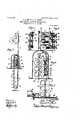
- Fig. 4 is a rear view of one set 'of the transfer-rammers.
- Fig. 5 is a section on the line C of Fig. 4.
- Fig. 6 is an enlarged side view of the upper part of the'chain elevator; and
- Fig. 7 1s a side view of the transfer-carriage, partly broken away.
- the turret comprises a shield covering the guns 2 and a cylindrical chamber 3 ⁇ below the guns, having a floor 4 ⁇ adapted to sup ort the ammunition-hoisting mechanism.
- he present invention does not relate to the particular construction of the turret or the arrangement of the guns in the turret, and hence no detailed descri tion of these parts is necessary.
- Within .the turret are vertically-arranged tracks -5, upon whichl elevator-cars c travel to convey the ammunition from the lower part of the turret to the guns.
- an elevator d for raising the ammunition from the handling-room 6 into the turret.
- a second ser1es of rammers g are located adjacent to the elevatord and adapted to convey the ammunition from the transfercar to the elevating-car c.
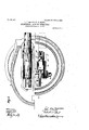
- the elevator d comprises two sprocket-chains. 7, running over sprocket-- ,wheels 8, supported on a stand 9, which is carried by t e floor 4 of the turret.
- Pivotally connectedv to the chains are a series of flights 10, which are curved to convenientlyv hold the ammunition.
- Each of the flights is provided with a spur 11, which rests against a link of the chain and holds lthe 'flight in proper horizontal positionron the ascending ranch of the' chains.
- Each flight is also povided with an arm 12, which' engages av ed projection 13 at the upper end of the frame 9 as the flight approaches the sprocketwheel, and the flight is thus folded in upon the chains and retains this position in passing over the sprocket-wheel and down on the descending branch of theY chains, ⁇ as illustrated in Fig. 6.
- the chain conveyer passes under suitable guide sprockets 14, said sprockets being carried by the floor of the hoist-well, which well rotates with the turret.
- An openin 15 is provided in the floor of the turret for t e passage of the chain conveyer, and a hood or casing 16 covers the conveyer and the opening.
- the shutters are pivoted, and' each set is connected by a link 31.
- the apparatus illustrated and described is capable of handling a charge of ammunition in three parts, which may include, for instance, a projectile and two bags of powder. It will be understood,how ⁇ ever, that either one or more sections of the charge of ammunition may behandled at a time.
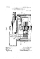
- the transfer-car e Between the chain conveyer'and the lower station of the track for the'elevating-car c is located the transfer-car e. As shown in Figs. 1 and 7 this car. has three compartments adapted to reg ⁇ ister with three 4flights of the chain elevator IOO and to receive three sections of a charge of charges of ammunition are entirely inclosed ammunition. preferably c vlindrical, being thus covered and adapte to protect the powder from sparks.
- the car is provided with wheels l and mounted on suitable rails 18, and means are provided for shifting it from a position registering with the chain conveyer to a posit-ion registering with the elevator-car.
- the ⁇ l said means are an'electrlc motor 19 and a screw 20.
- the elevating-car c maybe of any suitable construction. As shown in Fig. 3, it is provided with three shelves or supports for the ammunition, which register lwith the compartments in the transfer-car when the elevating-car is at its lower station.
- Two sets of transfer-rammers of any suitable construction are provided, one for transferring a charge from the chain elevator to the transfer-car and another for transferring it from the transfer-car to the elevating-car.
- These sets of rammers are substantially similar.
- Referring to Figs. 5 and 6, which represent t-he triple rammerf, 21 indicates three remmers carried by racks 22, which slide in a frame 23 and are operated by pinions 24 on avertical shaft 25.- The shaft 25 is driven bya motor 26 and suitable connections.
- the construction and operation of the rammers g and f may be the same, and a detailed description of the rammers g will therefore be omitted.
- the rammers g are locate between the branches of the chain elevator d, as shown in Figs. 3 and 6.
- the rammers g are driven by an independent motor 27.
- Any suitable oWer mechanism is provided for operating t e elevating-car c and the chain elevator da It will be understood that a complete set of the apparatus above described may be supplied for each gun in the turret and that the apparatus may be in some instances used for supplyin ammunition to guns which are not mounte in revolving turrets. This a paratus greatly expedites the handling of t e ammunition.
- compartments 17 are by the casing and shutters during the.. time they are in the chain elevator and in the transfer-car, thus orreatly reducing the danger of' igniting suoli charges by sparks from the turret.
- ammunit-iomclevating mechanism the combination with a gun, of an elevator adapted to raise ammunition from the handling-room, a second elevator adapted tol deliver the ammunition at the breech of the gun, a transfer-car between said elevators, a rammer adapted to move the ammunition from the first elevator to the transfer-car, and a second rammer adapted to .move the ammunition from the transfre-car to the second elevator.
- ammunition-elevating mechanism the combination with a gun, of a chain elevator adapted to raise the ammunition from the handhn -room, an ⁇ elevating-car adapted to deliver t e ammunition at the breech ot' the gun, a transfer-car between said' elevators, a series of rammers adapted to transfer elevators at said lower stat-ion.
- n ammunition-elevating mechanism the combination with a gun, of an elevator adapted to raise the. ammunition from the handling-room, a second elevator ada ted to deliver ammunition at the breech of t e gun, and a transfer-car between the upper station of the first-named elevator and the lower station of the second elevator, the said stations being laterally displaced and the car being movable to' register with each of said stations.
- the combination with a turret and a gun mounted therein of an elevator adapted to raise ammunition from the handling-room into the turret,- a second elevator within the turret adapted to deliver ammunition at the breech of the gun, the upper station of the former elevator and the lower station of the latter being out of register, and an intermediate transfer-"carl movable to re ister with each of said stations and adapte to hold a charge of ammunition.
Landscapes
- Engineering & Computer Science (AREA)
- General Engineering & Computer Science (AREA)
- Lift-Guide Devices, And Elevator Ropes And Cables (AREA)
Description
190.909,455. PATBNTBD JAN. 9,1906. J. P. MEIGS & 19.1. sToUT. AMMUNITION HOISTING MBGHANISM.-
APPLICATION FILBDVSEPT. 14, 1904.v
` 3 SHEETS-SEEE?I 1.
n@ b4 il M@ PATENTED JAN. 9, 1906.
, s SHEETS-SHEET z.
wvl/tow alito/muws J. F. MEIGS dz R. P. STOUT. AMMUNITION HOISTING MECHANISM. APPLICATION IVILBD s221214, 1904 10.809,455. BATENTED JN. 9,*19o6 J. F. MEIGS & R. P'. sToUT. AMMUNITION HoIsyTING MEGHANISM.
3 SHEETS-SHEET 3.
APPLIOATIDN FILED SEPT. 14, 1904.
wwwnmi hymn/hoz? UNITED sTATEs PATENT oEEIcE.
JOHN F. MEIGS AND ROBERT P. STOUT, vOF SOUTH BETHLEHEM, PENN- 'f SYLVANIA, ASSIGNORSTO BETHLEHEM STEEL COMPANY, OF SOUTH BETHLEHEM, PENNSYLVANIA, A CORPORATION OF PENNSYLVANIA.
ANIMUNITIQN-HOISTING .NIEOHANIS'M- Specication of Letters Patent. Application nea september 14,1004. serial 110,224,440.
Patented Jan. 9, 190e.
To all whom, it may concern.-
Be it known that we, JOHN F. MEIGs and ROBERT P. SToU'T, citizens of the United States, and residents of South Bethlehem, Northampton county, and State of Pennsylvania, have invented certain newand useful Improvements in Ammunition-Hoisting -is.a plan view, partly in section on the line A and partly in section on the line B, Fig. 1. Fig. 3 is a side elevation of the hoistingapparatus. Fig. 4 is a rear view of one set 'of the transfer-rammers. Fig. 5 is a section on the line C of Fig. 4. Fig. 6 is an enlarged side view of the upper part of the'chain elevator; and Fig. 7 1s a side view of the transfer-carriage, partly broken away.
Referring to the drawings, @indicates aV rotating turret or shield mounted on circular bearings 1 in a protecting-wall or barbette b. The turret comprises a shield covering the guns 2 and a cylindrical chamber 3` below the guns, having a floor 4` adapted to sup ort the ammunition-hoisting mechanism. he present invention does not relate to the particular construction of the turret or the arrangement of the guns in the turret, and hence no detailed descri tion of these parts is necessary. Within .the turret are vertically-arranged tracks -5, upon whichl elevator-cars c travel to convey the ammunition from the lower part of the turret to the guns. Near the center of the turret and supported by the licor 4 is an elevator d for raising the ammunition from the handling-room 6 into the turret. Between the. elevator d and the track 5 is a transfer-car e, onto which the= ammunition is loaded by a series of rammers f. A second ser1es of rammers g are located adjacent to the elevatord and adapted to convey the ammunition from the transfercar to the elevating-car c.
I As shown, the elevator d comprises two sprocket-chains. 7, running over sprocket-- ,wheels 8, supported on a stand 9, which is carried by t e floor 4 of the turret. Pivotally connectedv to the chains are a series of flights 10, which are curved to convenientlyv hold the ammunition. Each of the flights is provided with a spur 11, which rests against a link of the chain and holds lthe 'flight in proper horizontal positionron the ascending ranch of the' chains. Each flight is also povided with an arm 12, which' engages av ed projection 13 at the upper end of the frame 9 as the flight approaches the sprocketwheel, and the flight is thus folded in upon the chains and retains this position in passing over the sprocket-wheel and down on the descending branch of theY chains,` as illustrated in Fig. 6. The chain conveyer passes under suitable guide sprockets 14, said sprockets being carried by the floor of the hoist-well, which well rotates with the turret. An openin 15 is provided in the floor of the turret for t e passage of the chain conveyer, and a hood or casing 16 covers the conveyer and the opening. The openings in said casing 16, through .which the rammer o crates and lthrough which ammunition is disc arged into transfer-car e, as also the..openings in each end of said car e, are closed by shutters 30, which shutters are opened onlyA when` necessary to move ammunition into orout of said openings, thus preventing sparks from dropping into the handling-room or from igniting powder charges contained in hoist d in transfer-car e. (See Fig. 7.) As
shown, the shutters are pivoted, and' each set is connected by a link 31.
The apparatus illustrated and described is capable of handling a charge of ammunition in three parts, which may include, for instance, a projectile and two bags of powder. It will be understood,how`ever, that either one or more sections of the charge of ammunition may behandled at a time. Between the chain conveyer'and the lower station of the track for the'elevating-car c is located the transfer-car e. As shown in Figs. 1 and 7 this car. has three compartments adapted to reg` ister with three 4flights of the chain elevator IOO and to receive three sections of a charge of charges of ammunition are entirely inclosed ammunition. preferably c vlindrical, being thus covered and adapte to protect the powder from sparks. The car is provided with wheels l and mounted on suitable rails 18, and means are provided for shifting it from a position registering with the chain conveyer to a posit-ion registering with the elevator-car. The` l said means, as shown, are an'electrlc motor 19 and a screw 20.
- The elevating-car c maybe of any suitable construction. As shown in Fig. 3, it is provided with three shelves or supports for the ammunition, which register lwith the compartments in the transfer-car when the elevating-car is at its lower station.
Two sets of transfer-rammers of any suitable construction are provided, one for transferring a charge from the chain elevator to the transfer-car and another for transferring it from the transfer-car to the elevating-car. These sets of rammers, as'v shown, are substantially similar. Referring to Figs. 5 and 6, which represent t-he triple rammerf, 21 indicates three remmers carried by racks 22, which slide in a frame 23 and are operated by pinions 24 on avertical shaft 25.- The shaft 25 is driven bya motor 26 and suitable connections. The construction and operation of the rammers g and fmay be the same, and a detailed description of the rammers g will therefore be omitted. As compactness is an essential feature of the mechanism, owing to the limited s ace in the turret, the rammers g are locate between the branches of the chain elevator d, as shown in Figs. 3 and 6. The rammers g are driven by an independent motor 27. Any suitable oWer mechanism is provided for operating t e elevating-car c and the chain elevator da It will be understood that a complete set of the apparatus above described may be supplied for each gun in the turret and that the apparatus may be in some instances used for supplyin ammunition to guns which are not mounte in revolving turrets. This a paratus greatly expedites the handling of t e ammunition. While one charge is being placed in the gun from the elevatmg-car c the ,transfer-car is supplied with a succeeding charge and broug t back into position to register with the triple rammer By a slight movement of the chain e evator a third charge is brought into position to register with the triple rammerf, as a number of char es may be carried simultaneously by the cIiain elevator. It will thus be seen that the elevatin -car c may be loaded instantly when it reac es its lower station, and the gun maybe ired as rapidly as the car c can be moved' up and down and the charges placed in the gun. At the same time the handlingroom is practically shut off from the turret and protected from falling sparks. The
These compartments 17 are by the casing and shutters during the.. time they are in the chain elevator and in the transfer-car, thus orreatly reducing the danger of' igniting suoli charges by sparks from the turret. Y
Having described the invention, what we claim, and desire to secure by Letters Patent, is
1'. In ,ammunition-elevatin mechanism, the combination with a gun, o two elevators and an intermediate transfer-car adapted to transfer ammunition from the handlingroom to the gun. y
2. In ammunition-elevatin mechanism, the combination with a gun,y of an elevatingcar adapted to deliver ammunition at the breech of the guna a` second elevator adapted to deliver ammunition at the lower station of the elevatin car, and a transfer-car located between sai 3. In ammunition elevating mechanism, the combination with a gun, of an elevator adapted to deliver ammunition at the breech of the gun, a second elevator adapted to raise ammunition from the handling-room, said elevators being'out of register with each other, and a transfer-car movable to regiters with said elevators alternately.
.4. In ammunit-iomclevating mechanism, the combination with a gun, of an elevator adapted to raise ammunition from the handling-room, a second elevator adapted tol deliver the ammunition at the breech of the gun, a transfer-car between said elevators, a rammer adapted to move the ammunition from the first elevator to the transfer-car, and a second rammer adapted to .move the ammunition from the transfre-car to the second elevator.
5. In ammunition-elevating mechanism, the combination with a gun, of a chain elevator adapted to raise the ammunition from the handhn -room, an `elevating-car adapted to deliver t e ammunition at the breech ot' the gun, a transfer-car between said' elevators, a series of rammers adapted to transfer elevators at said lower stat-ion.
IOO
IOS
IIO
the ammunition from the chain elevator to .the transfer-car, and a second series of ran1- mers adapted to transfer the ammunition from the transfer-car to the elevating-car.
6. The combination with a turret and a gun mounted therein, said turret having a, floor extending over the handling-room, of an elevator extendino through an opening in said Hoor from the handling-room into the- IIS ` extending through an opening in nition, a transfer-car movable on said floor, and a plurality of rammers adapted to move .a number of sections of ammunition simultaneously from said chain elevator to said car. 8. In an ammunition-elevating mechanism, the combination-with a gun, of an elevator adapted to raise the ammunition from the handling-room, a second elevator adapt ed to deliver the ammunition at the breech of the gun, and means, including a rammer, for transferring the ammunition from the first-mentioned elevator to the second elevator.
9. The'combination with a turret and a Vun mounted therein, said turret `having a oor extending over the handling-room, of a chain elevator supported on said floor and the floor to the handling-room, and a casing or cover over said elevator and opening, said elevator being rovided with pivoted flights, and means For folding said flights upon the chains Within said casing whereby a casing of minimum size may be used.
10. In ammunition-hoisting mechanism,
the combination with a cham elevator, a transfer-car, and anelevating-car, of a multiple rammer adapted to move several sec-- tions of ammunition simultaneously from the chain elevator tothe transfer-car, and a second multiple rammer located between the branches of the chain elevator and ada te'd to move several sections of ammunitionl om the transfer-car to the elevating-car.
11. The combination with a turret, and a un mounted therein, said turret having a oor extending over the handling-room, of an elevating ap aratus supported on and extending throug an opening in said oor, and a normally closed casing extending over said elevator, whereby sparks are prevented from assing below the turret-floor said casingv aving openings for the passageof ammunition and means for normally closing the same. 12. The combination with a turret, and al n mounted therein, said turret having a oor extending over the handling-room, of an elevating ap aratus supported on and extending through an opening in said floor, a
normally closed casing extending over sa d elevator,said casing havin o eningsthrou h which the ammunition is sc arged into t e turret, and shutters for normally closing said openin s.
13. n ammunition-elevating mechanism, the combination with a gun, of an elevator adapted to raise the. ammunition from the handling-room, a second elevator ada ted to deliver ammunition at the breech of t e gun, and a transfer-car between the upper station of the first-named elevator and the lower station of the second elevator, the said stations being laterally displaced and the car being movable to' register with each of said stations.
14. In ammunition-elevating mechanism, the combination with a turret and a gun mounted therein, of an elevator adapted to raise ammunition from the handling-room into the turret,- a second elevator within the turret adapted to deliver ammunition at the breech of the gun, the upper station of the former elevator and the lower station of the latter being out of register, and an intermediate transfer-"carl movable to re ister with each of said stations and adapte to hold a charge of ammunition.
15. In ammunition-elevating mechanism,
the combination with a turret and a gun mounted therein, of an elevator adapted to raise ammunition from the handling-room to the turret, a second elevator adapted to deliver the ammunition at gun, each of said elevators being adapted to simultaneously hold a plurality of sections of ammunition and the upper station of the first-named elevator and the lower station of the second elevator being at the same elevation, :but out of register with each other, a vhorizontally-movable transfer-ear arranged between said stations and adapted to register with 'each of them, and rammers adapted to transfer the ammunition fromv the rst elevator-to the transfericar and from the said transfer-car to the second elevator.
In testimony whereof we have signed our the breech ofthe names-to this specification in the presence of two subscribing witnesses.
lJOHN F. MEIGS.
ROBERT P. STOUT.
Priority Applications (1)
| Application Number | Priority Date | Filing Date | Title |
|---|---|---|---|
| US22444004A US809455A (en) | 1904-09-14 | 1904-09-14 | Ammunition-hoisting mechanism. |
Applications Claiming Priority (1)
| Application Number | Priority Date | Filing Date | Title |
|---|---|---|---|
| US22444004A US809455A (en) | 1904-09-14 | 1904-09-14 | Ammunition-hoisting mechanism. |
Publications (1)
| Publication Number | Publication Date |
|---|---|
| US809455A true US809455A (en) | 1906-01-09 |
Family
ID=2877936
Family Applications (1)
| Application Number | Title | Priority Date | Filing Date |
|---|---|---|---|
| US22444004A Expired - Lifetime US809455A (en) | 1904-09-14 | 1904-09-14 | Ammunition-hoisting mechanism. |
Country Status (1)
| Country | Link |
|---|---|
| US (1) | US809455A (en) |
Cited By (1)
| Publication number | Priority date | Publication date | Assignee | Title |
|---|---|---|---|---|
| US5111730A (en) * | 1989-09-18 | 1992-05-12 | Rheinmetall Gmbh | Apportioning apparatus for loading a loading tray with a variable number of propelling charge modules |
-
1904
- 1904-09-14 US US22444004A patent/US809455A/en not_active Expired - Lifetime
Cited By (1)
| Publication number | Priority date | Publication date | Assignee | Title |
|---|---|---|---|---|
| US5111730A (en) * | 1989-09-18 | 1992-05-12 | Rheinmetall Gmbh | Apportioning apparatus for loading a loading tray with a variable number of propelling charge modules |
Similar Documents
| Publication | Publication Date | Title |
|---|---|---|
| US809455A (en) | Ammunition-hoisting mechanism. | |
| US4690031A (en) | Automatic loader for an armored vehicle having a rotatable turret | |
| ES2750178T3 (en) | Device for feeding medium-caliber ammunition with turntable | |
| CA1239043A (en) | Assembly for feeding ammunition in armored vehicle | |
| US2378191A (en) | Ammunition feed | |
| US3170372A (en) | Loader and magazine mechanism | |
| US653071A (en) | Apparatus for supplying ammunition to turret or barbette guns. | |
| US1185249A (en) | Ammunition-hoist. | |
| US704985A (en) | Ammunition-hoist for ordnance. | |
| US20020144590A1 (en) | Automatic loading process and system for a weapon mounted on a ship | |
| US669896A (en) | Apparatus for supplying ammunition to turret or barbette guns. | |
| US1388575A (en) | Furnace | |
| US847917A (en) | Ammunition-hoisting apparatus for ordnance. | |
| US709436A (en) | Ammunition-hoist for ordnance. | |
| US1084947A (en) | Ammunition-hoisting mechanism. | |
| US938560A (en) | Ammunition-hoisting apparatus for heavy ordnance. | |
| US1410895A (en) | Ammunition-hoisting apparatus for ordnance | |
| US877210A (en) | Conveyer. | |
| US1402401A (en) | Ammunition-hoisting apparatus for ordnance | |
| US1188629A (en) | Ammunition hoisting and loading apparatus of heavy ordnance. | |
| US497704A (en) | canet | |
| US1609315A (en) | Hoisting and conveying apparatus | |
| US736075A (en) | Ammunition-hoist for ordnance. | |
| US397310A (en) | schneider | |
| US419921A (en) | Tave adolphe canet |