US809454A - Traversing mechanism. - Google Patents
Traversing mechanism. Download PDFInfo
- Publication number
- US809454A US809454A US25717805A US1905257178A US809454A US 809454 A US809454 A US 809454A US 25717805 A US25717805 A US 25717805A US 1905257178 A US1905257178 A US 1905257178A US 809454 A US809454 A US 809454A
- Authority
- US
- United States
- Prior art keywords
- wheels
- track
- car
- sections
- traction
- Prior art date
- Legal status (The legal status is an assumption and is not a legal conclusion. Google has not performed a legal analysis and makes no representation as to the accuracy of the status listed.)
- Expired - Lifetime
Links
- 238000005266 casting Methods 0.000 description 3
- 230000002093 peripheral effect Effects 0.000 description 3
- 238000006563 Carroll rearrangement reaction Methods 0.000 description 1
- 229910001208 Crucible steel Inorganic materials 0.000 description 1
- 238000010276 construction Methods 0.000 description 1
Images
Classifications
-
- B—PERFORMING OPERATIONS; TRANSPORTING
- B62—LAND VEHICLES FOR TRAVELLING OTHERWISE THAN ON RAILS
- B62D—MOTOR VEHICLES; TRAILERS
- B62D57/00—Vehicles characterised by having other propulsion or other ground- engaging means than wheels or endless track, alone or in addition to wheels or endless track
Definitions
- the invention relates to apparatus for transporting excavators and other heavy machinery from place to place, especially where there is no railroad upon which the machines can be moved, and has for its object to provide machines of the character described with two movable track-sections and duplicate sets of traction-wheels adapted to alternately engage the corresponding track-sections, together with means, preferably operated by power mechanism on the machine,
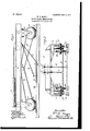
- Figure 1 is a side elevation of a car constituting the support of an excavator or other heavy machine having the invention applied thereto.
- Fig. 2 is an end elevation thereof.
- A indicates the body of a car of the character usually employed in supporting'the operating mechanism of an excavator or steam-shovel or other heavy machine which is intended to be moved from place to place as the conditions of the work may require.
- the car-body may of course have any desired construction; but in machines of this character it is customary to build the car-body of rolled, forged, or cast steel sections.
- two supporting-trucks B B Secured to the car-body are two supporting-trucks B B, which in the present instance consist of a series of clevised racket-castings attached to the car-body frame, the depending arms of said brackets being provided with bearings to receive the axles or pins E of the traction-wheels upon which the car is mounted.
- the car is provided with four such brackets, which constitute trucks for the several sets of traction-wheels.
- the axles or pins E upon which turn the castings F, each of which consists of two wheels G and H and an intermediate s rocket wheel J, the several parts preferalily being formed as an integral structure.
- Each of the wheels G and H has a true circular contour for approximately half of its periphery but the other half of its periphery is flattened out or given an elliptical form, as indicated, the two wheels being substantially alike in form and being arranged with respect to each other, so that the normal or flattened or elliptical half of the other wheel.
- Two track-sections K and M each somewhat longer than the wheel-base of the car, provide a movable way upon which the car is transported or traversed.
- the wheels G run upon the outer set of tracks K, and the wheels H engage the tracks M, and by reason of the peculiar arrangement of the wheels, hereinbefore described, the respective sets of wheels G and H alternately engage the corresponding tracksections K and M.
- the tracks K are connected by cross-bars P, and the tracks M are similarly connected by cross-bars N, which bars serve to hold the tracks pro erly spaced apart and also serve as points of attachment for draft mechanism, by means of which the respective track-sections are advanced or pulled forward, as will be hereinafter described.
- the sprocket-wheels J forming a part of the wheel-castings, are employed to drive the wheels, and for this purpose are connected by sprocket-chains L to a power-shaft T on the car-body, which power-shaft is preferably driven from a prime mover on the car, which of course may be the operating-engine of the excavator or other machine.
- the car is alternately supported on-the sets of wheels G and H and the corresponding tracks K and M, and while the wheels H, for instance, are carrying the car forward on the tracks M the track-section K is free to be slid forward, and while the wheels G are carrying the car forward upon the tracks K the track-section M is relieved from the weight of the machine, and said track-section may then be slid forward.
- any appropriate mechanism for altercircular half of one wheel lies adjacent to the nately sliding the track-sections M and K forward may be employed.
- the means for advancing the track-sections consists of two steam-cylinders S S, the pistons of which are severally connected by ropes or cables R and R to the cross ends P and N. Said cylinders and pistons therefore constitute a simplified form of steam-engine, which serves to drag the connected traclesections forward.
- the cylinders may of course be controlled by suitable valve mechanism which in turn is operated from shaft T or other moving part of the machine, or said cylinders may be constructed without valves, as shown, in which event as the car advances along track-section M, for instance, the piston in cylinder S is pulled forward by cable R by reason of the relative movement of the car and traclvsection until said track-section is relieved of the weight of the car, when the steam-pressure in the cylinder will return the piston to the rear of cylinder S. and pull the track-section. M forward.
- the track-section K is similarly advanced by the operation of cylinder S.
- the invention comprises an automatic mechanism in which the two track-sections are alternately engaged by the corresponding traction-Wheels, the free section being advanced while the car is moving along the other section, so that the machine is capable of being moved to any distance either by way of the wagon-roads or across country upon its own rails.
- the rails in the respective track-sections may be provided with suitable means for varying the direction of the track in order to make the necessary turns or curves of the road or to avoid obstructions.
- Apparatus for traversing or transporting excavators or other heavy machinery comprising two movable parallel track-sections, two sets of traction-wheels on the machine, the wheels of each set having flattened, peripheral portionslying adjacent circular portions of the other set, means for driving the traction-Wheels, and means for advancing the respective track-sections as they are alternately freed from the cooperating traction-wheels.
- Apparatus for traversing or transporting excavators or other heavy machinery comprising two movable parallel track-sections, two sets of traction-wheels on the machine, the Wheels of each set having flattened, peripheral portions lying adjacent circular portions of the other set, means for driving the traction-Wheels, and power mechanism on the machine connected to the respective track-sections for advancing the latter as they are alternately freed from the cooperating traction-wheels.
- Apparatus for traversing or transporting excavators or other heavy machinery comprising two movable parallel track-sec tions, two sets of traction-wheels on the machine, the wheels of each set having flattened, peripheral portions lying adjacent circular portions of the other set, means for driving the traction-wheels, and power mechanism on the machine having cables connected to the respective track-sections for advancing the latter as they are alternately freed from the cooperating traction-wheels.
Landscapes
- Engineering & Computer Science (AREA)
- Chemical & Material Sciences (AREA)
- Combustion & Propulsion (AREA)
- Transportation (AREA)
- Mechanical Engineering (AREA)
- Machines For Laying And Maintaining Railways (AREA)
Description
No- 809,454. PATENTED JAN. 9, 1906.
W. E. MAGIE. TRAVERSING MECHANISM.
APPLICATION FILED APR. 24. 1905.
UNITED STATES PORATION OF WISCONSIN.
PATENT OFFICE.
WILLIAM E. MAGIE, OF SOUTH MILWAUKEE, WISCONSIN, ASSIGNOR TO THE BUCYRUS COMPANY, OF SOUTH MILWAUKEE, IVISCON SIN A COR- TRAVERSING MECHANISM.
Specification of Letters Patent.
Patented Jan. 9, 1906.
Application filed April 24, 1905. Serial No. 257-178.
-do hereby declare the following to be a full, clear, and exact description of the invention,
such as will enable others skilled in the art to which it appertains to make and use the same.
The invention relates to apparatus for transporting excavators and other heavy machinery from place to place, especially where there is no railroad upon which the machines can be moved, and has for its object to provide machines of the character described with two movable track-sections and duplicate sets of traction-wheels adapted to alternately engage the corresponding track-sections, together with means, preferably operated by power mechanism on the machine,
for alternately advancing the respective track-sections when they are disengaged by the wheels.
In the accompanying drawings, Figure 1 is a side elevation of a car constituting the support of an excavator or other heavy machine having the invention applied thereto. Fig. 2 is an end elevation thereof.
Referring to the drawings, A indicates the body of a car of the character usually employed in supporting'the operating mechanism of an excavator or steam-shovel or other heavy machine which is intended to be moved from place to place as the conditions of the work may require. The car-body may of course have any desired construction; but in machines of this character it is customary to build the car-body of rolled, forged, or cast steel sections. Secured to the car-body are two supporting-trucks B B, which in the present instance consist of a series of clevised racket-castings attached to the car-body frame, the depending arms of said brackets being provided with bearings to receive the axles or pins E of the traction-wheels upon which the car is mounted. As illustrated, the car is provided with four such brackets, which constitute trucks for the several sets of traction-wheels. Mounted on the bearings aforesaid are the axles or pins E, upon which turn the castings F, each of which consists of two wheels G and H and an intermediate s rocket wheel J, the several parts preferalily being formed as an integral structure. Each of the wheels G and H has a true circular contour for approximately half of its periphery but the other half of its periphery is flattened out or given an elliptical form, as indicated, the two wheels being substantially alike in form and being arranged with respect to each other, so that the normal or flattened or elliptical half of the other wheel. Two track-sections K and M, each somewhat longer than the wheel-base of the car, provide a movable way upon which the car is transported or traversed. The wheels G run upon the outer set of tracks K, and the wheels H engage the tracks M, and by reason of the peculiar arrangement of the wheels, hereinbefore described, the respective sets of wheels G and H alternately engage the corresponding tracksections K and M. The tracks K are connected by cross-bars P, and the tracks M are similarly connected by cross-bars N, which bars serve to hold the tracks pro erly spaced apart and also serve as points of attachment for draft mechanism, by means of which the respective track-sections are advanced or pulled forward, as will be hereinafter described.
The sprocket-wheels J, forming a part of the wheel-castings, are employed to drive the wheels, and for this purpose are connected by sprocket-chains L to a power-shaft T on the car-body, which power-shaft is preferably driven from a prime mover on the car, which of course may be the operating-engine of the excavator or other machine.
It will be seen that the car is alternately supported on-the sets of wheels G and H and the corresponding tracks K and M, and while the wheels H, for instance, are carrying the car forward on the tracks M the track-section K is free to be slid forward, and while the wheels G are carrying the car forward upon the tracks K the track-section M is relieved from the weight of the machine, and said track-section may then be slid forward. Thus the car rolls ahead, while the track-sections M and K are alternately advanced as they are freed from engagement with the corresponding traction-wheels.
Any appropriate mechanism for altercircular half of one wheel lies adjacent to the nately sliding the track-sections M and K forward may be employed. In the form of the invention illustrated the means for advancing the track-sections consists of two steam-cylinders S S, the pistons of which are severally connected by ropes or cables R and R to the cross ends P and N. Said cylinders and pistons therefore constitute a simplified form of steam-engine, which serves to drag the connected traclesections forward. The cylinders may of course be controlled by suitable valve mechanism which in turn is operated from shaft T or other moving part of the machine, or said cylinders may be constructed without valves, as shown, in which event as the car advances along track-section M, for instance, the piston in cylinder S is pulled forward by cable R by reason of the relative movement of the car and traclvsection until said track-section is relieved of the weight of the car, when the steam-pressure in the cylinder will return the piston to the rear of cylinder S. and pull the track-section. M forward. The track-section K is similarly advanced by the operation of cylinder S.
As thus described, the invention comprises an automatic mechanism in which the two track-sections are alternately engaged by the corresponding traction-Wheels, the free section being advanced while the car is moving along the other section, so that the machine is capable of being moved to any distance either by way of the wagon-roads or across country upon its own rails. Of course the rails in the respective track-sections may be provided with suitable means for varying the direction of the track in order to make the necessary turns or curves of the road or to avoid obstructions.
What I claim is 1. Apparatus for traversing or transporting excavators or other heavy machinery,
comprising two movable parallel track-sections, inner and outer sets of traction-wheels on the machine cooperating with the respective track-sections, the Wheels of each set having flattened portions, the flat portions of the respective sets lying adjacent the nor mal portions of the other set, whereby the machine is alternately supported by the respective sets of Wheels, and means for advancing the respective track-sections as they are disengaged from the cooperating set of wheels.
2. Apparatus for traversing or transporting excavators or other heavy machinery, comprising two movable parallel track-sections, two sets of traction-wheels on the machine, the wheels of each set having flattened, peripheral portionslying adjacent circular portions of the other set, means for driving the traction-Wheels, and means for advancing the respective track-sections as they are alternately freed from the cooperating traction-wheels.
3. Apparatus for traversing or transporting excavators or other heavy machinery, comprising two movable parallel track-sections, two sets of traction-wheels on the machine, the Wheels of each set having flattened, peripheral portions lying adjacent circular portions of the other set, means for driving the traction-Wheels, and power mechanism on the machine connected to the respective track-sections for advancing the latter as they are alternately freed from the cooperating traction-wheels.
4. Apparatus for traversing or transporting excavators or other heavy machinery, comprising two movable parallel track-sec tions, two sets of traction-wheels on the machine, the wheels of each set having flattened, peripheral portions lying adjacent circular portions of the other set, means for driving the traction-wheels, and power mechanism on the machine having cables connected to the respective track-sections for advancing the latter as they are alternately freed from the cooperating traction-wheels.
In testimony whereof I aflix my signature in presence of two witnesses.
WM. E. MAGIE.
Witnesses:
H. B. HAYDEN, P. C. Bonn.
Priority Applications (1)
| Application Number | Priority Date | Filing Date | Title |
|---|---|---|---|
| US25717805A US809454A (en) | 1905-04-24 | 1905-04-24 | Traversing mechanism. |
Applications Claiming Priority (1)
| Application Number | Priority Date | Filing Date | Title |
|---|---|---|---|
| US25717805A US809454A (en) | 1905-04-24 | 1905-04-24 | Traversing mechanism. |
Publications (1)
| Publication Number | Publication Date |
|---|---|
| US809454A true US809454A (en) | 1906-01-09 |
Family
ID=2877935
Family Applications (1)
| Application Number | Title | Priority Date | Filing Date |
|---|---|---|---|
| US25717805A Expired - Lifetime US809454A (en) | 1905-04-24 | 1905-04-24 | Traversing mechanism. |
Country Status (1)
| Country | Link |
|---|---|
| US (1) | US809454A (en) |
-
1905
- 1905-04-24 US US25717805A patent/US809454A/en not_active Expired - Lifetime
Similar Documents
| Publication | Publication Date | Title |
|---|---|---|
| US809454A (en) | Traversing mechanism. | |
| CN102229402A (en) | Rubber-tired container gantry crane and steering device thereof | |
| US1209209A (en) | Motor-truck. | |
| US1189501A (en) | Agricultural machine. | |
| US686004A (en) | Radial hoist. | |
| US894916A (en) | Traveling hoist. | |
| US3257967A (en) | Drives for overhead haulage vehicles | |
| US284147A (en) | Road-engine | |
| US1346152A (en) | Loading and hauling automobile-truck | |
| US962398A (en) | Axle construction for car-trucks. | |
| US1007412A (en) | Machine for turning car-axle journals. | |
| US564597A (en) | dayies | |
| US963387A (en) | Trolley. | |
| CN223100845U (en) | Bottom support device of self-unloading freight box | |
| US491933A (en) | Crane | |
| US797301A (en) | Traversing mechanism. | |
| DE386539C (en) | Device for steering caterpillars with roller support frames | |
| US681632A (en) | Cable-power. | |
| US213143A (en) | Improvement in hydraulic elevators | |
| US1121751A (en) | Horseless farm-vehicle. | |
| US767865A (en) | Brake for overhead electrically-driven locomotives. | |
| US882618A (en) | Locomotive. | |
| US1091125A (en) | Universal carriage-locomotive. | |
| US509758A (en) | morgan | |
| KR20200025677A (en) | Excavator that can run railroad |