US809391A - Type-writing machine. - Google Patents
Type-writing machine. Download PDFInfo
- Publication number
- US809391A US809391A US19803304A US1904198033A US809391A US 809391 A US809391 A US 809391A US 19803304 A US19803304 A US 19803304A US 1904198033 A US1904198033 A US 1904198033A US 809391 A US809391 A US 809391A
- Authority
- US
- United States
- Prior art keywords
- spacing
- spacing member
- vibratory
- carriage
- movement
- Prior art date
- Legal status (The legal status is an assumption and is not a legal conclusion. Google has not performed a legal analysis and makes no representation as to the accuracy of the status listed.)
- Expired - Lifetime
Links
- 230000033001 locomotion Effects 0.000 description 72
- 230000007246 mechanism Effects 0.000 description 68
- 238000010276 construction Methods 0.000 description 12
- 230000001276 controlling effect Effects 0.000 description 10
- 230000004048 modification Effects 0.000 description 6
- 238000012986 modification Methods 0.000 description 6
- 230000000977 initiatory effect Effects 0.000 description 5
- 230000009471 action Effects 0.000 description 4
- 238000004804 winding Methods 0.000 description 3
- 230000006870 function Effects 0.000 description 2
- 230000006978 adaptation Effects 0.000 description 1
- 230000008901 benefit Effects 0.000 description 1
- 238000006243 chemical reaction Methods 0.000 description 1
- 230000001419 dependent effect Effects 0.000 description 1
- 230000000694 effects Effects 0.000 description 1
- 230000008030 elimination Effects 0.000 description 1
- 238000003379 elimination reaction Methods 0.000 description 1
- JCCNYMKQOSZNPW-UHFFFAOYSA-N loratadine Chemical compound C1CN(C(=O)OCC)CCC1=C1C2=NC=CC=C2CCC2=CC(Cl)=CC=C21 JCCNYMKQOSZNPW-UHFFFAOYSA-N 0.000 description 1
- 238000012423 maintenance Methods 0.000 description 1
- 229920000136 polysorbate Polymers 0.000 description 1
- 230000001105 regulatory effect Effects 0.000 description 1
- 238000009877 rendering Methods 0.000 description 1
- 230000013707 sensory perception of sound Effects 0.000 description 1
Images
Classifications
-
- B—PERFORMING OPERATIONS; TRANSPORTING
- B41—PRINTING; LINING MACHINES; TYPEWRITERS; STAMPS
- B41J—TYPEWRITERS; SELECTIVE PRINTING MECHANISMS, i.e. MECHANISMS PRINTING OTHERWISE THAN FROM A FORME; CORRECTION OF TYPOGRAPHICAL ERRORS
- B41J19/00—Character- or line-spacing mechanisms
- B41J19/18—Character-spacing or back-spacing mechanisms; Carriage return or release devices therefor
- B41J19/34—Escapement-feed character-spacing mechanisms
- B41J19/40—Escapements having a single pawl or like detent
Definitions
- My invention relates to type-writing machines, and more particularly to the carriagefeed mechanism thereof.
- the main object of the invention is to provide a carriage-feed mechanism for typewriting machines wherein, the detaining member and the spacing member may both be carried in their entirety upon the rockerarm or vibratory member and the said spacing member will be so constructed and arranged as to be controlled during the printing interval and the feeding interval by the movement thereof relative to and in conjunction with the resulting pressure thereon from the carriage-controlling mechanism.
- a further object is to provide-such a mech anism wherein the initial movement of the spacing member to permit the feed of the carriage will be coincident with the reversal of the direction of movement of the vibratory member and with the resultant reversal of the direction of pressure thereon from the carriage-controlling mechanism, wherein the continued movement of said member will permit a rapid yet continuous feed of the car riage and an even and noiseless movement thereof and wherein a substantially constant load on the finger-keys will be maintained during the printing interval.
- a still further object is to provide such a mechanism wherein the feed of the carriage
- a still further object is to provide such a mechanism wherein the movement of the spacing member thereof during the spacing interval will be positive-that is to say, not dependent upon opposed spring tensions-thus permitting a construction and an arrangement of parts which in use will not require 'a fine adjustment relative to other parts of or spring tensions on the machine,
- a still further object is to provide such a mechanism wherein the spacing member will be operative to initiate the feeding movement of the carriage instantly upon the re versal ofthe direction of movement of said vibratory member irrespective of the extent of the direct movement thereof requisite to permit the imprint of the type.
- a still further object is to provide such a mechanism wherein the parts will be simple in construction and compact in arrangement, which will be durable and eflicient in use and which when once assembled will be adapted to meet the requirements of general use and of the various classes and styles of operators without further adjustment or regulation; and a still further object is to provide such a mechanism wherein the detaining member and spacing member may be set well apart without liability of the carriage-controlling mechanism escaping therefrom in a manner to occasion a double spacing thereof.
- the invention consists, primarily, in providing in a type-writing machine a carriage feed mechanism comprising a carriage-controlling mechanism, a vibratory member, a detaining member, and a rotary spacing member carried thereby, the axis of said spacing member being substantially at right angles to the contact-face thereof; means whereby pressure from the engagement of the carriagecontrolling mechanism with said spacing member during the direct movement of said vibratory member holds said spacing mem ber stationary and said spacing member is tial reversal of movement of said vibratory member, such rotation of said spacing member permitting axial movement thereof; means whereby said spacing member is re- V permitted to rotate instantly upon the ini- 10o stored to its normal position after each spac- 1o 5 ing, and connections between said vibratory member and the several key-levers whereby said detaining member and said spacing member are caused to successively engage said carriage-controlling mechanism, and in such 11o other novel features of construction and arrangement of parts as are hereinafter set forth and described, and more particularly pointed out in the claims
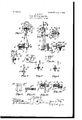
- Figure 1 is a rear elevation of a carriage-feed mechanism embodying the preferred form of my invention.
- Fig. 2 is a side elevation thereof.
- Fig. 3 is a plan view thereof.
- Fig. 4 is an en larged view of the spacing member, showing the means by which the rotation of said mem ber permits axial movement thereof.
- Fig. 5 is an enlarged view of the spacing member in connection with the rack member of the carriage-controlling mechanism, illustrating one construction of the contacting face of said rack member.
- Figs. 6, 7, and 8 are diagrammatic views showing, respectively, the relation of the several parts when at rest at the limit of the direct movement of the vibratory member and at the instant of the reversal of the direction of movement of said vibratory member.
- Fig. 9 is a modification of the means by whichthe rotation of the spacing member permits axial movement thereof.
- Fig. 10 is an enlarged sectional view thereof.
- Figs. 11 and 12 illustrate a still further modification of such means, showing a back elevation and a plan thereof, respectively.
- Fig. 13 is an enlarged view illustrating a desirable construction of the rack member of the carriage-controlling mechanism.
- Fig. 14 is a side view of the rotary spacing-member support, showing the means whereby the spacing-member-returning spring may be tensioned in assembling the device; and
- Fig. 15 is a side view of the preferred form of spacing and detaining members, on an enlarged scale.
- the spacing member is operative largely through pressure thereon from the carriage-controlling mechanism, which term contemplates v not only the star-wheel or other rack member but the mainspring of the carriage. Not shown.
- the vibratory member or rocker-arm 6 mounted with the usual retracting-spring b and its tensioning means b ,'buflers c and c for limiting the extent of vibration of said arm in each direction, and a cross-bar d, by means of which said rocker-arm is connected by the links (1 to the universal bar (not shown) and actuated by the several key-levers. (Also not shown.)
- the detaining member 0 mounted on the said vibratory member I) is the detaining member 0, adapted to normally engage the rack member a and hold the carriage-controlling mechanism stationary.
- this detaining member being well known to this art will not be herein described beyond that it is pivotally mounted on said rocker-arm, is provided with a spring e to cause it to fly backward upon its release from engagement with the rack member into position to more readily engage the succeeding tooth thereof upon its return movement, and preferably is provided with an extension 6 which follows the periphery of the spacing member 7b to prevent the rack member skipping during the spacing interval or printing interval.
- This invention relates more particularly, however, to the construction of the spacing member and inits arrangement in relation to these other or equivalent elements.
- the said spacing member is carried by a yoke formed by angular plates f g, mounted on the vibi atory member I), having oppositely-disposed bearings therein.
- this member comprises an annular flange it, made integrally with an axle or shaft h, the axis or which is substantially at right angles to the contact-face of said flange.
- This axle is mounted in the bearings in the plates f g and is free to both rotate and move axially therein, as will more fully appear here'- inafter.
- various means for limiting the axial movement thereof in conjunction with the plate f may be employed.
- I provide the shaft 71/ with a shoulder 7L3, formed by turning the end thereof down in such relation to the said plate that the axial movement of said shaft and its flange will be. limited to one-half a letter-space.
- the detaining member 6 and the spacing member h are reciprocated by the vibratory member I), so as to alternately engage the rack membenof the carriage controlling mechanism.
- the pressure of the carriage spring tends to give said spacing member axial movement; but through the frictional engagement between said rack member and said spacing member the movement of the vibratory member controls the direction of this pressure in a manner to tend to rotate said spacing member.
- I provide means whereby the tendency of said spacing member to rotate thereunder during the direct movement of the vibratory member will prevent axial movement of said rotary spacing member and instantly with the reversal of the direction of movement of said vibratory member will'permit said spacing member to rotatev and move axially under the reversed direction of pressure thereon.
- I may also after the initiation of the feeding interval take advantage of the normal direct pressure from the carriage-controlling mechanism to expedite the feed.
- this means takes the form of a winding way 72, passing about the shaft or axle h, the pitch of or the number of such winds per inch regulating to a great extent the speed of operation of the spacing member.
- a guide-pin g Carried by the plate g and seated in said way 71, is a guide-pin g, which to permit the regulationof the relation of the said pin and the walls of the way is preferably screw-threaded above its point-bearing.
- the pin g and the walls of the way It constitute opposed bearings, one of which is graduated and movable relative to the other, and which through the rotation of the spacing member 72, control the feed of said member through the pressure thereon from the carriage-controlling mechanism.
- Figs. 11 and 12 I show a modification of the spacing member h, which differs from the preferred form in the following respects
- the shaft h is provided with a bearing-pin h, which in addition to controlling the movement of the said spacing member h, as heretofore described, limits the amount of its feed by contact with the shoulder 9 formed on the yoke-plate g.
- This'plate is provided with an opposed bearing with which the pin 7L contacts and by reason of which the tendency of said shaft to rotate in one direction serves to prevent movement thereof and its rotation in the opposite direction permits an axial feed thereof. To minimize friction at this point,
- this bearing may, if desired, comprise a small antifriction-roller 9 with the periphery of which the pin h engages.
- Figs. 9 and 10 I show a still further modification relating to this feature of my invention
- means for returning the spacing member h to normal after disengagement with the rack member a is provided, preferably consisting of the spring 'i, which is adapted to rotate the shaft 7L.
- This spring is of very light tension, as merely power enough to overcome the friction on the various bearings is required for this purpose. To facilitate the adjustment of this spring in assembling, I
- a torsion-spring is desirable as giving the proper reversal of movement of the flange h with a compact structure
- the normal position of the spacing member may be fixed by the collar on the axle or shaft h, as shown in Figs. 1 to 4, inclusive, or by engagement of said flange with the plate g, as shown in Figs. 11 and 12.
- the above is the sole function of the spring 'i, and while I have shown a torsion-spring in the drawings any spring acting axially or torsionally of'said shaft would so operate.
- the arrangement of these parts is such as to bring the spacing member into alinement with the detaining member, with the result that the disengagement of the one and the engagement of the other occurs upon the same plane, avoiding that drop which tends in practice to vary the load on the key-levers and which might tend to prevent the balancing of parts hereinafter referred to.
- Figs. 5 and 13 I have shown two forms of rack-member teeth, which are applicable in connection with the spacing mechanism heretofore described. Each of these is designed to occasion what maybe termed a va riable radial contact between the flange h and the rack member, first to insure stability upon the direct movement of the vibratory member; second, to expedite the feeding movement after the initiation thereof. Incident to each of these constructions is the absence of corners, which would tend to contact with the spacing member, and, as has been demonstrated, to break and chip thereon. The form shown in Fig.
- Fig. 13 consists of a widened tooth with one corner scarfed off laterally, as at M,
- scarfed portion extends substantially tangentially of the spacing member, with the result substantially as above except that the variance in the radial contact results from the movement of the vibratory member and that the detaining member need not be provided with the extension e.
- this rotation of the flange 7L and its shaft or axle it permits the carriage to feed forward, the way 7L2 following the guidepin g to permit both rotary and axial movement.
- the number of winds per inch of the way 71 will of course regulate the extent of rotation required to permit a definite quantity of feed, the fewer the winds or less the pitch of said way the greater being the speed of feed.
- the shoulder k serves to limit the quantity of axial feed of the spacing member, which preferably is, as stated heretofore, a half of a letter-space only, to enable an operator by aising the space bar with a slight double touch to cause the said spacing member, and hence the carriage, to feed forward a halfspaoe while under the control of said spacing member, thus permitting the splitting of spaces to facilitate the correction of copy.
- the spring i is tensioned by the forward feed of the member h and immediately upon the disengagement of the rack member a from said spacing member restores said spacing member to its normal position.
- said spring causes it to rotate in a direction opposite to that in feeding, not only bringing the flange to rest on the same plane as the detaining member 0, but giving it all the rotary movement required to take up all looseness due to structural inequalities of or wear on the opposed bearing-faces, permitting the feed, thus avoiding movement coextensive with such looseness upon the engagement of the said spacing member 7L with the rack member a.
- the pin 9 may be adjusted to take up such wear or looseness, if desired; but the action of the spring 71 is such as to always bring the opposed hearings in contact, as above described, irrespective of the quantity of such wear or looseness, whether these faces comprise the side of the way 7L2 and pin 9, Figs. 1 to 4, or the fixed guide 9 Figs. 9 and 10, or of the pin 7L and the roller g Figs. 11 and 12.
- the first engagement of the wheela with the spacing member h is adjacent to the periphery of the latter above the scarfed end of the tooth, which insures the application of the pressure prior to the initial feed upon a long radius.
- the wheel turns so as to bring the scarfed end into action adjacent to the axle or shaft h or upon 12 5 a short radius, thus minimizing the pressure due to movement of the vibratory member and causing the direct pressure herein referred to to act substantially along the axis of the spacing member, which accelerates the 1 0 feed through the elimination of friction between these members due to the rotation of the said flange.
- the pin h is forced downward upon the graduated opposed bearing, the periphery of the roller 9 Upon the reversal of this pressure the pin h rises and follows the periphery of said roller through the feeding movement until it overrides said roller and contacts with the shoulder 9 which limits the feed of said spacing member and the carriage controlling mechanism while under its control.
- this mode of operation is substantially identical with that of the preferred form, as the spring i in this form also will always maintain that contact between the pin h and the roller 9 necessary to avoid looseness and that the diameter of the roller 9 corresponds with the pitch of the way 7L2.
- the detaining member 6 operates in the usual manner to insure a reengagement with the rack member a.
- the spacing member h is held perfectly stationary during the direct movement of the vibratory member I), and by reason of its contact-face being on the same plane as that of the detaining member the carriage is not permitted to move until the end of such direct movement as ordinarily limited by the buffer 0, which is coincident, or substantially so, with the imprint of the type.
- the spacing member becomes operative and, as heretofore described, both permits the rapid, even, and continuous feed of the carriage and aids in the return of the vibratory member.
- the spring I) is used principally to cause a quick initiation of the return of the rocker-arm or vibratory member.
- the bufler 0 acts in the usual way to limit the extent of holding contact of the rack member with the detaining member e.
- a carriagefeed mechanism comprising a carriage controlling mechanism, a vibratory member, a detaining member and a rotary spacing member carried thereby, the axis of said spacing member being substantially at right angles to the contact-face thereof, means whereby pressure from the engagement of the carriagecontrolling mechanism with said spacing member during the direct movement of said vibratory member holds said spacing member stationary and said spacing member is permitted to rotate instantly upon the initial reversal of movement of said vibratory member, such rotation of said spacing member permitting axial movement thereof, means whereby said spacing member is restored to its normal position after each spacing and connections between said vibratory member and the several key-levers whereby said detaining member and said spacing member are caused to successively engage said carriagecontrolling mechanism.
- a carriagefeed mechanism comprising a carriage controlling mechanism, a vibratory member, a detaining member and a rotary spacing member consisting of a flange and an axle or shaft therefor extending at substantially right angles to the contact face thereof, carried by said vibratory member, opposed bearings carried respectively by said vibratory member and said shaft whereby pressure from the engagement of the carriage-controlling mechanism with said spacing member during the direct movement of said vibratory member,
- a carriage- I 5 feed mechanism comprising a carriage controlling mechanism, a vibratory member, a detaining member and a rotary spacing member consisting of a flange and an axle or shaft therefor extending at substantially right angles to the contact-face thereof, carried by said vibratory member, opposed bearings carried respectively by said vibratory mem ber and said shaft whereby pressure from the engagement of the carriage-controlling mechanism with said spacing member, during the direct movement of said vibratory member, holds said spacing member stationary, and said spacing member is permitted to rotate instantly upon the initial reversal of move- 0 ment of said vibratory member, said rotation of said spacing member permitting axial movement thereof, means whereby the axial movement of said spacing member is limited to a portion of a letter-space, a spring where- 3 5 by said spacing member is restored to its normal position after each spacing, and connections between said vibratory member and the several key-levers whereby said detaining member and said spacing member are caused 0 to successively engage said carriage-
- a carriagefeed mechanism comprising a carriage corrtrolling mechanism, a vibratory member, a
- detaining member and a rotary spacing member consisting of a flange and an axle or shaft therefor extending at substantially right angles to the contact-face thereof, carried by said vibratory member, opposed bearings carried by said vibratory member and said shaft respectively whereby pressure from the engagement of the carriage-controlling mechanism with said spacing member during the direct movement of said vibratory member holds said spacing member stationary and said spacing member is permitted to rotate instantly upon the initial reversal of movement of said vibratory member, such rotation of said spacing member permitting axial 6o movement thereof, a spring adapted to rotate said shaft whereby said spacing member is restored to its normal position after each spacing and said opposed bearings are forced into intimate contact with each other, and
- a carriagefeed mechanism comprising a carriage-controlling mechanism a vibratory member, a detaining member and a rotary spacing mem ber consisting of a flange and an axle or shaft therefor extending at substantially right angles to the contact-face thereof, carried by said vibratory member, opposed bearings carried respectively by said vibratory member and said shaft whereby pressure from the engagement of the carriage-controlling mechanism with said spacing member during the direct movement of said vibratory member, holds the spacing member stationary, and said spacing member is permitted to rotate instantly upon the initial reversal of movement of said vibratory member, such rotation permitting axial movement thereof, a spring whereby said spacing member is restored to its normal position after each spacing, said carriage-controlling mechanism comprising arack member, the teeth of which present contact faces to said spacing member on different planes whereby engagement of said parts will be at different radii during the printing and the spacing intervals, and connections between said vibratory member and the several key-levers, whereby said detaining member and said spacing
- a carriagefeed mechanism comprising a carriagecontrolling mechanism, a vibratory member, a yoke carried thereby having oppositely-dis posed bearings therein, a detaining member mounted on said vibratory member, a spacing member comprising a flange and an axle or shaft having awinding way therein mounted in said bearings and extending at substantially right angles to the contact-face of said flange, a guide carried by said yoke and engaging said way whereby pressure from the engagement of the carriage-controlling mechanism with said spacing member during the direct movement of said vibratory member holds said'spacing member stationary, and said spacing member is permitted to rotate instantly upon the initial reversal of movement of said vibratory member, such rotation of said spacing member permitting axial movement thereof, a spring whereby said spacing member is restored to its normal position after each spacing, and connections between said vibratory member and the several key-levers whereby said detaining member and said spacing member are caused to successively engage said carriage controlling mechanism.
- a carriagefeed mechanism comprising a carriage-controlling mechanism, a vibratory'member, a yoke carried thereby having oppositely-disposed bearings therein, a detaining member mounted on said vibratory member, a spacing member comprising a flange and an axle or shaft therefor having a winding Way therein, mounted in said bearings and extending at substantially right angles to the contactface of said flange, a guide comprising a screw-threaded point-bearing carried by said yoke and engaging said way whereby pressure from the engagement of the carriagecontrolling (mechanism with said spacing member during the direct movement of said vibratory member holds said spacing member stationary, and said spacing member is permitted to rotate instantly upon the initial reversal of movement of said vibratorymemb er,
- a carriagefeed mechanism comprising a carriage controlling mechanism, a vibratory member, a yoke carried thereby having oppositely-disposed bearings therein, a detaining member mounted on said vibratory member, a spacing member comprising a flange and an axle or shaft having a winding way therein mounted in said bearings and extending at substantially right angles to the contact-face of said flange,
- a carriagefeed mechanism comprising a carriagecontrolling mechanism, a vibratory member, a detaining member and a rotary spacing member consisting of a flange and an axle or shaft therefor extending at substantially right angles to the contact -face thereof, carried by said vibratory member, opposed bearings carried respectively by said vibratory member and said shaft whereby pressure from the engagement of the carriage-controlling mechanism with said spacing member during the direct movement of said vibratory member holds said spacing member stationary, and said spacing member is permitted to rotate instantly upon the initial reversal of movement of said vibratory member, such rotation of said spacing member permitting axial movement thereof, a spring whereby said spacing member is restored to its normal position after each spacing and connections between said vibratory member and the several key-levers whereby said detaining member and said spacing member are caused to successively engage said carriage controlling mechanism, said detaining member being provided with an extension alined with and following the top periphery of said spacing member;
Landscapes
- Character Spaces And Line Spaces In Printers (AREA)
Description
No'. 809,391. PATENTED JAN. 9, 1906.
L. G. NEPF. TYPE WRITING MACHINE.
APPLICATION FILED MAR.14, 1904.
* UNITED STATES LOUIS C. NEFF, OFNEW YORK, N. Y.
TYPE-WRITING MACHINE.
Specification of Letters Patent.
Patented Jan. 9, 1906.
Application filed March 14,1904. Serial No. 198,033.
To all whom, it may concern.
Be it known that I, LoUrs C. NEFF, a citizen of the United States, residing in the borough of Brooklyn, city of New York, county of Kings, and'State of New York, have in vented certain new and useful Improvements in Type-Writing Machines, of which the following is a specification, reference being had therein to the accompanying drawings, which form a part thereof. I
My invention relates to type-writing machines, and more particularly to the carriagefeed mechanism thereof.
The main object of the invention is to provide a carriage-feed mechanism for typewriting machines wherein, the detaining member and the spacing member may both be carried in their entirety upon the rockerarm or vibratory member and the said spacing member will be so constructed and arranged as to be controlled during the printing interval and the feeding interval by the movement thereof relative to and in conjunction with the resulting pressure thereon from the carriage-controlling mechanism.
A further object is to provide-such a mech anism wherein the initial movement of the spacing member to permit the feed of the carriage will be coincident with the reversal of the direction of movement of the vibratory member and with the resultant reversal of the direction of pressure thereon from the carriage-controlling mechanism, wherein the continued movement of said member will permit a rapid yet continuous feed of the car riage and an even and noiseless movement thereof and wherein a substantially constant load on the finger-keys will be maintained during the printing interval.
A still further object is to provide such a mechanism wherein the feed of the carriage A still further object is to provide such a mechanism wherein the movement of the spacing member thereof during the spacing interval will be positive-that is to say, not dependent upon opposed spring tensions-thus permitting a construction and an arrangement of parts which in use will not require 'a fine adjustment relative to other parts of or spring tensions on the machine,
A still further object is to provide such a mechanism wherein the spacing member will be operative to initiate the feeding movement of the carriage instantly upon the re versal ofthe direction of movement of said vibratory member irrespective of the extent of the direct movement thereof requisite to permit the imprint of the type.
A still further object is to provide such a mechanism wherein the parts will be simple in construction and compact in arrangement, which will be durable and eflicient in use and which when once assembled will be adapted to meet the requirements of general use and of the various classes and styles of operators without further adjustment or regulation; and a still further object is to provide such a mechanism wherein the detaining member and spacing member may be set well apart without liability of the carriage-controlling mechanism escaping therefrom in a manner to occasion a double spacing thereof.
The invention consists, primarily, in providing in a type-writing machine a carriage feed mechanism comprising a carriage-controlling mechanism, a vibratory member, a detaining member, and a rotary spacing member carried thereby, the axis of said spacing member being substantially at right angles to the contact-face thereof; means whereby pressure from the engagement of the carriagecontrolling mechanism with said spacing member during the direct movement of said vibratory member holds said spacing mem ber stationary and said spacing member is tial reversal of movement of said vibratory member, such rotation of said spacing member permitting axial movement thereof; means whereby said spacing member is re- V permitted to rotate instantly upon the ini- 10o stored to its normal position after each spac- 1o 5 ing, and connections between said vibratory member and the several key-levers whereby said detaining member and said spacing member are caused to successively engage said carriage-controlling mechanism, and in such 11o other novel features of construction and arrangement of parts as are hereinafter set forth and described, and more particularly pointed out in the claims hereto appended.
Referring to the drawings, Figure 1. is a rear elevation of a carriage-feed mechanism embodying the preferred form of my invention. Fig. 2 is a side elevation thereof. Fig. 3 is a plan view thereof. Fig. 4 is an en larged view of the spacing member, showing the means by which the rotation of said mem ber permits axial movement thereof. Fig. 5 is an enlarged view of the spacing member in connection with the rack member of the carriage-controlling mechanism, illustrating one construction of the contacting face of said rack member. Figs. 6, 7, and 8 are diagrammatic views showing, respectively, the relation of the several parts when at rest at the limit of the direct movement of the vibratory member and at the instant of the reversal of the direction of movement of said vibratory member. Fig. 9 is a modification of the means by whichthe rotation of the spacing member permits axial movement thereof. Fig. 10 is an enlarged sectional view thereof.
. Figs. 11 and 12 illustrate a still further modification of such means, showing a back elevation and a plan thereof, respectively. Fig. 13 is an enlarged view illustrating a desirable construction of the rack member of the carriage-controlling mechanism. Fig. 14 is a side view of the rotary spacing-member support, showing the means whereby the spacing-member-returning spring may be tensioned in assembling the device; and Fig. 15 is a side view of the preferred form of spacing and detaining members, on an enlarged scale.
Like letters refer to like parts throughout the several views.
In the accompanying drawings I have shown my invention as applied to a wellknown type of wheel and rocker-arm mechanism and will describe it more particularly in connection therewith, although it is capable of adaptation with but slight mechanical variation to various constructions of feed mechanisms employing a rack member and a dog-support, one of which is movable relative to and across the other.
The spacing member, as will more fully appear hereinafter, is operative largely through pressure thereon from the carriage-controlling mechanism, which term contemplates v not only the star-wheel or other rack member but the mainspring of the carriage. Not shown.)
Mounted below the wheel or rack member a in hangers carried by the frame of the machine is the vibratory member or rocker-arm 6, provided with the usual retracting-spring b and its tensioning means b ,'buflers c and c for limiting the extent of vibration of said arm in each direction, and a cross-bar d, by means of which said rocker-arm is connected by the links (1 to the universal bar (not shown) and actuated by the several key-levers. (Also not shown.) Mounted on the said vibratory member I) is the detaining member 0, adapted to normally engage the rack member a and hold the carriage-controlling mechanism stationary. The construction and function of this detaining member being well known to this art will not be herein described beyond that it is pivotally mounted on said rocker-arm, is provided with a spring e to cause it to fly backward upon its release from engagement with the rack member into position to more readily engage the succeeding tooth thereof upon its return movement, and preferably is provided with an extension 6 which follows the periphery of the spacing member 7b to prevent the rack member skipping during the spacing interval or printing interval. This invention relates more particularly, however, to the construction of the spacing member and inits arrangement in relation to these other or equivalent elements. The said spacing member is carried by a yoke formed by angular plates f g, mounted on the vibi atory member I), having oppositely-disposed bearings therein. Preferably this member comprises an annular flange it, made integrally with an axle or shaft h, the axis or which is substantially at right angles to the contact-face of said flange. This axle is mounted in the bearings in the plates f g and is free to both rotate and move axially therein, as will more fully appear here'- inafter. In feeding the carriage the extent of movement of the spacing member must be definite, and in this type of spacing member various means for limiting the axial movement thereof in conjunction with the plate f may be employed. Preferably, however, I provide the shaft 71/ with a shoulder 7L3, formed by turning the end thereof down in such relation to the said plate that the axial movement of said shaft and its flange will be. limited to one-half a letter-space.
The detaining member 6 and the spacing member h are reciprocated by the vibratory member I), so as to alternately engage the rack membenof the carriage controlling mechanism. During this operation the pressure of the carriage spring tends to give said spacing member axial movement; but through the frictional engagement between said rack member and said spacing member the movement of the vibratory member controls the direction of this pressure in a manner to tend to rotate said spacing member.
To utilize this pressure in controlling the spacing member, I provide means whereby the tendency of said spacing member to rotate thereunder during the direct movement of the vibratory member will prevent axial movement of said rotary spacing member and instantly with the reversal of the direction of movement of said vibratory member will'permit said spacing member to rotatev and move axially under the reversed direction of pressure thereon. I may also after the initiation of the feeding interval take advantage of the normal direct pressure from the carriage-controlling mechanism to expedite the feed. In the preferred form .of the invention this means takes the form of a winding way 72, passing about the shaft or axle h, the pitch of or the number of such winds per inch regulating to a great extent the speed of operation of the spacing member. Carried by the plate g and seated in said way 71, is a guide-pin g, which to permit the regulationof the relation of the said pin and the walls of the way is preferably screw-threaded above its point-bearing. The pin g and the walls of the way It constitute opposed bearings, one of which is graduated and movable relative to the other, and which through the rotation of the spacing member 72, control the feed of said member through the pressure thereon from the carriage-controlling mechanism.
In Figs. 11 and 12 I show a modification of the spacing member h, which differs from the preferred form in the following respects The shaft h is provided with a bearing-pin h, which in addition to controlling the movement of the said spacing member h, as heretofore described, limits the amount of its feed by contact with the shoulder 9 formed on the yoke-plate g. This'plate is provided with an opposed bearing with which the pin 7L contacts and by reason of which the tendency of said shaft to rotate in one direction serves to prevent movement thereof and its rotation in the opposite direction permits an axial feed thereof. To minimize friction at this point,
which is desirable owing to the long radius on which the pin h acts, this bearing may, if desired, comprise a small antifriction-roller 9 with the periphery of which the pin h engages. In Figs. 9 and 10 I show a still further modification relating to this feature of my invention,
appertaining more particularly, however, to
mechanical details by which the pin g is dispensed with and a fixed guide 9 corresponding in pitch with the way 7L2, 1S broached or otherwise formed integrally with the yokeplate g.
In each of the forms of the invention described means for returning the spacing member h to normal after disengagement with the rack member a is provided, preferably consisting of the spring 'i, which is adapted to rotate the shaft 7L. This spring is of very light tension, as merely power enough to overcome the friction on the various bearings is required for this purpose. To facilitate the adjustment of this spring in assembling, I
provide the plate f with concentric openings f, adapted, respectively, to receive the end of the spring i. A torsion-spring is desirable as giving the proper reversal of movement of the flange h with a compact structure, and,
furthermore, as producing a slight cushioning effect toward the end of the feeding interval. The normal position of the spacing member may be fixed by the collar on the axle or shaft h, as shown in Figs. 1 to 4, inclusive, or by engagement of said flange with the plate g, as shown in Figs. 11 and 12. The above is the sole function of the spring 'i, and while I have shown a torsion-spring in the drawings any spring acting axially or torsionally of'said shaft would so operate. -Preferably the arrangement of these parts is such as to bring the spacing member into alinement with the detaining member, with the result that the disengagement of the one and the engagement of the other occurs upon the same plane, avoiding that drop which tends in practice to vary the load on the key-levers and which might tend to prevent the balancing of parts hereinafter referred to.
In Figs. 5 and 13 I have shown two forms of rack-member teeth, which are applicable in connection with the spacing mechanism heretofore described. Each of these is designed to occasion what maybe termed a va riable radial contact between the flange h and the rack member, first to insure stability upon the direct movement of the vibratory member; second, to expedite the feeding movement after the initiation thereof. Incident to each of these constructions is the absence of corners, which would tend to contact with the spacing member, and, as has been demonstrated, to break and chip thereon. The form shown in Fig. 5 varies from the ordinary star-wheel in having the contact-face of each tooth scarfed off toward the point, as at a, so that the teeth when on a vertical plane will contact with the flange adjacent to its periphery and the scarfed portion will engage the flange near the axle h immediately after the initial feed. The form shown in Fig. 13 consists of a widened tooth with one corner scarfed off laterally, as at M,
which scarfed portion extends substantially tangentially of the spacing member, with the result substantially as above except that the variance in the radial contact results from the movement of the vibratory member and that the detaining member need not be provided with the extension e.
The operation of 'my carriage-feed mechanism, as illustrated in the accompanying drawings, is substantially as follows: With the depression of each key lever the vibratory member or rocker-arm b is reciprocated, thus disengaging the rack member a of the carriage-controlling mechanism and the detaining member 6, which normally are as shown in Fig. 6, and transferring the pressure therefrom to the spacing member h. The faces of said members being parallel insures a perfectly smooth even action without ar or noise. This transfer is accomplished without permitting the rack member to escape from the spacing member through the extension 0 on the detaining member in the construction shown in Figs. 1 to 5, inclusive, or through the increased width and scarfed corner of the rack member in the construction shown in Fig. 13. Both of these constructions insure a substantially simultaneous disengagement of the rack member from the detaining member and engagement thereof with the spacing member and a quick reversal of the operation during the spacing interval, thus permitting said members to be well set apart to insure proper clearance. Further direct movement of said vibratory member results in such a frictional engagement of the rack member and flange h as results in so diverting the pressure of the carriagecontrolling mechanism as to tend to turn this flange upon its axis in the direction of the arrow, Fig. 7. This action, through the way 7L2 and pin g, Figs. 1 to 4, or fixed guide 9 Figs. 9 and 10, and pin 7L and roller 9 Figs. 11 and 12, or other opposed bearings, tends to force the spacing member and carriage-controlling mechanism backward, a. tendency which is opposed by the same degree of pressure causing it, (or by the collary' or plate 9,) thus producing a balanced condition, resulting in the maintenance of the carriage stationary during the printing interval or the entire direct movement of the vibratory member. Instantly upon the reversal of the direction of movement of said vibratory member and substantially simultaneously with the imprint of the type, irrespective of the extent of this di rect movement, the direction of pressure from the rack member a upon the spacing member h is reversed, as indicated by the arrow in Fig. 8, thus tending to rotate the member 7L in the opposite direction. In the preferred form of the invention this rotation of the flange 7L and its shaft or axle it permits the carriage to feed forward, the way 7L2 following the guidepin g to permit both rotary and axial movement. The number of winds per inch of the way 71, will of course regulate the extent of rotation required to permit a definite quantity of feed, the fewer the winds or less the pitch of said way the greater being the speed of feed.
I have found that in use the above rotary axial-movement relieves the flange h from radial pressure to an extent to occasion the continued feed of the spacing member largely through the direct pressure thereon from the carriagecontrolling mechanism, the rotation of said member being after the initiation of the feed merely incidental to the continuance thereof. I have also found that through continued rotation under direct pressure the radial travel of the flange 7L tends to be greater than the movement of the vibratory member, so that the engagement thereof with the rack member occasions a reaction upon the said vibratory member which tends to restore the parts to their former position, thus aiding in causing thevibratory member to act uniformly with the imprint of the type and also rendering a light tension on the retractingspring feasible.
In the preferred form of the invention the shoulder k serves to limit the quantity of axial feed of the spacing member, which preferably is, as stated heretofore, a half of a letter-space only, to enable an operator by aising the space bar with a slight double touch to cause the said spacing member, and hence the carriage, to feed forward a halfspaoe while under the control of said spacing member, thus permitting the splitting of spaces to facilitate the correction of copy.
The slight resistance due to the friction be tween the pin 9 and the walls of the way if is sufficient, in conjunction with the tensioning of the spring 11, to avoid a decided drop of the spacing member during the feeding interval, thus eliminating to a limited extent the noise incident to the carriage-feed.
The spring i is tensioned by the forward feed of the member h and immediately upon the disengagement of the rack member a from said spacing member restores said spacing member to its normal position. In restoring the spacing member to its former position said spring causes it to rotate in a direction opposite to that in feeding, not only bringing the flange to rest on the same plane as the detaining member 0, but giving it all the rotary movement required to take up all looseness due to structural inequalities of or wear on the opposed bearing-faces, permitting the feed, thus avoiding movement coextensive with such looseness upon the engagement of the said spacing member 7L with the rack member a. In the preferred form of the invention the pin 9 may be adjusted to take up such wear or looseness, if desired; but the action of the spring 71 is such as to always bring the opposed hearings in contact, as above described, irrespective of the quantity of such wear or looseness, whether these faces comprise the side of the way 7L2 and pin 9, Figs. 1 to 4, or the fixed guide 9 Figs. 9 and 10, or of the pin 7L and the roller g Figs. 11 and 12.
In the modification shown in Fig. 5 the first engagement of the wheela with the spacing member h is adjacent to the periphery of the latter above the scarfed end of the tooth, which insures the application of the pressure prior to the initial feed upon a long radius. After the initiation of the feed the wheel turns so as to bring the scarfed end into action adjacent to the axle or shaft h or upon 12 5 a short radius, thus minimizing the pressure due to movement of the vibratory member and causing the direct pressure herein referred to to act substantially along the axis of the spacing member, which accelerates the 1 0 feed through the elimination of friction between these members due to the rotation of the said flange.
In the modification shown in Fig. 13 the upper part of the scarfed portion a of the rack member first engages the flange upon a long radius, and this radius shortens in proportion to the extent of such engagement. This form of rack member also avoids that breaking or chipping of corners incidental to.
tory member I), the pin h is forced downward upon the graduated opposed bearing, the periphery of the roller 9 Upon the reversal of this pressure the pin h rises and follows the periphery of said roller through the feeding movement until it overrides said roller and contacts with the shoulder 9 which limits the feed of said spacing member and the carriage controlling mechanism while under its control. It will be observed that this mode of operation is substantially identical with that of the preferred form, as the spring i in this form also will always maintain that contact between the pin h and the roller 9 necessary to avoid looseness and that the diameter of the roller 9 corresponds with the pitch of the way 7L2. The detaining member 6 operates in the usual manner to insure a reengagement with the rack member a.
In all forms of the invention heretofore described the spacing member h is held perfectly stationary during the direct movement of the vibratory member I), and by reason of its contact-face being on the same plane as that of the detaining member the carriage is not permitted to move until the end of such direct movement as ordinarily limited by the buffer 0, which is coincident, or substantially so, with the imprint of the type. Immediately'upon the initial return movement of said vibratory member the spacing member becomes operative and, as heretofore described, both permits the rapid, even, and continuous feed of the carriage and aids in the return of the vibratory member. The spring I) is used principally to cause a quick initiation of the return of the rocker-arm or vibratory member. The bufler 0 acts in the usual way to limit the extent of holding contact of the rack member with the detaining member e.
The proper disengagement of the spacing member from the rack member results from the speed of escapement in conjunction with the contour of the flange h of the spacing member, it being quite immaterial whether the spacing member be set into the detaining member 6 or the rack member broadened to compensate for the gap between the tops of the members h and e.
Inasmuch as the spacing member is operative at the instant of imprint of the type, it is apparent that the speed of escapement is coextensive with that of the operator, so that a uniform adjustment is in practice suitable for various styles and classes of operators and neither a double spacing nor a piling of type is possible.
It is not my intention to limit the invention to the precise details herein shown and described, as it is apparent that such may be varied without departing from the spirit and scope of my invention. I believe it to be new to provide a rotary spacing member having its contact-face at substantially right angles to its axis and means whereby its tendency to rotate in one direction will hold it stationary and its rotation in the reverse'direction will permit it to move axially to accomplish the feed and intend herein to claim such broadly.
Having described the invention, what I claim as new, and desire to have protected by Letters Patent, is-
1. In a type-writing machine, a carriagefeed mechanism comprising a carriage controlling mechanism, a vibratory member, a detaining member and a rotary spacing member carried thereby, the axis of said spacing member being substantially at right angles to the contact-face thereof, means whereby pressure from the engagement of the carriagecontrolling mechanism with said spacing member during the direct movement of said vibratory member holds said spacing member stationary and said spacing member is permitted to rotate instantly upon the initial reversal of movement of said vibratory member, such rotation of said spacing member permitting axial movement thereof, means whereby said spacing member is restored to its normal position after each spacing and connections between said vibratory member and the several key-levers whereby said detaining member and said spacing member are caused to successively engage said carriagecontrolling mechanism.
2. In a type-writing machine, a carriagefeed mechanism comprising a carriage controlling mechanism, a vibratory member, a detaining member and a rotary spacing member consisting of a flange and an axle or shaft therefor extending at substantially right angles to the contact face thereof, carried by said vibratory member, opposed bearings carried respectively by said vibratory member and said shaft whereby pressure from the engagement of the carriage-controlling mechanism with said spacing member during the direct movement of said vibratory member,
holds said spacing member stationary, and said spacing member is permitted to rotate instantly upon the initial reversal of move ment of said vibratory member, such rotation of said spacing member permitting axial movement thereof, a spring whereby said spacing member is restored to its normal position after each spacing, and connections between said vibratory member and the sev- IO eral key-levers whereby said detaining member and said spacing member are caused to successively engage said carriage-controlling mechanism.
3. In a type-writing machine, a carriage- I 5 feed mechanism comprising a carriage controlling mechanism, a vibratory member, a detaining member and a rotary spacing member consisting of a flange and an axle or shaft therefor extending at substantially right angles to the contact-face thereof, carried by said vibratory member, opposed bearings carried respectively by said vibratory mem ber and said shaft whereby pressure from the engagement of the carriage-controlling mechanism with said spacing member, during the direct movement of said vibratory member, holds said spacing member stationary, and said spacing member is permitted to rotate instantly upon the initial reversal of move- 0 ment of said vibratory member, said rotation of said spacing member permitting axial movement thereof, means whereby the axial movement of said spacing member is limited to a portion of a letter-space, a spring where- 3 5 by said spacing member is restored to its normal position after each spacing, and connections between said vibratory member and the several key-levers whereby said detaining member and said spacing member are caused 0 to successively engage said carriage-controlling mechanism.
4. In a type-writing machine, a carriagefeed mechanism comprising a carriage corrtrolling mechanism, a vibratory member, a
detaining member and a rotary spacing member consisting of a flange and an axle or shaft therefor extending at substantially right angles to the contact-face thereof, carried by said vibratory member, opposed bearings carried by said vibratory member and said shaft respectively whereby pressure from the engagement of the carriage-controlling mechanism with said spacing member during the direct movement of said vibratory member holds said spacing member stationary and said spacing member is permitted to rotate instantly upon the initial reversal of movement of said vibratory member, such rotation of said spacing member permitting axial 6o movement thereof, a spring adapted to rotate said shaft whereby said spacing member is restored to its normal position after each spacing and said opposed bearings are forced into intimate contact with each other, and
connections between said vibratory member and the several key-levers whereby said detaining member and said spacing member are caused to successively engage said carriage-controlling mechanism.
5. In a type-writing machine, a carriagefeed mechanism comprising a carriage-controlling mechanism a vibratory member, a detaining member and a rotary spacing mem ber consisting of a flange and an axle or shaft therefor extending at substantially right angles to the contact-face thereof, carried by said vibratory member, opposed bearings carried respectively by said vibratory member and said shaft whereby pressure from the engagement of the carriage-controlling mechanism with said spacing member during the direct movement of said vibratory member, holds the spacing member stationary, and said spacing member is permitted to rotate instantly upon the initial reversal of movement of said vibratory member, such rotation permitting axial movement thereof, a spring whereby said spacing member is restored to its normal position after each spacing, said carriage-controlling mechanism comprising arack member, the teeth of which present contact faces to said spacing member on different planes whereby engagement of said parts will be at different radii during the printing and the spacing intervals, and connections between said vibratory member and the several key-levers, whereby said detaining member and said spacing member are caused to successively engage said carriagecontrolling-mechanism rack member.
6. In a type-writing machine, a carriagefeed mechanism comprising a carriagecontrolling mechanism, a vibratory member, a yoke carried thereby having oppositely-dis posed bearings therein, a detaining member mounted on said vibratory member, a spacing member comprising a flange and an axle or shaft having awinding way therein mounted in said bearings and extending at substantially right angles to the contact-face of said flange, a guide carried by said yoke and engaging said way whereby pressure from the engagement of the carriage-controlling mechanism with said spacing member during the direct movement of said vibratory member holds said'spacing member stationary, and said spacing member is permitted to rotate instantly upon the initial reversal of movement of said vibratory member, such rotation of said spacing member permitting axial movement thereof, a spring whereby said spacing member is restored to its normal position after each spacing, and connections between said vibratory member and the several key-levers whereby said detaining member and said spacing member are caused to successively engage said carriage controlling mechanism.
7. In a type-writing machine, a carriagefeed mechanism comprising a carriage-controlling mechanism, a vibratory'member, a yoke carried thereby having oppositely-disposed bearings therein, a detaining member mounted on said vibratory member, a spacing member comprising a flange and an axle or shaft therefor having a winding Way therein, mounted in said bearings and extending at substantially right angles to the contactface of said flange, a guide comprising a screw-threaded point-bearing carried by said yoke and engaging said way whereby pressure from the engagement of the carriagecontrolling (mechanism with said spacing member during the direct movement of said vibratory member holds said spacing member stationary, and said spacing member is permitted to rotate instantly upon the initial reversal of movement of said vibratorymemb er,
such rotation of said spacing member permitting axial movement thereof, aspring whereby said spacing member is restored to its normal position after each spacing, and connec tions between said vibratory member and the several key levers, whereby said detaining member and said spacing member are caused to successively engage said carriage-controlling mechanism.
8. In a type-writing machine, a carriagefeed mechanism comprising a carriage controlling mechanism, a vibratory member, a yoke carried thereby having oppositely-disposed bearings therein, a detaining member mounted on said vibratory member, a spacing member comprising a flange and an axle or shaft having a winding way therein mounted in said bearings and extending at substantially right angles to the contact-face of said flange,
.a guide carried by said yoke engaging said way whereby pressure from the engagement of said carriage-controlling mechanism with said spacing member during the direct movement of said vibratory member holds said spacing member stationary and said spacing member is permitted to rotate instantly upon the initial reversal of movement of said vibratory member, such rotation of said spacing member permitting axial movement thereof, means whereby axial movement of said spacing member is limited to a portion of a letter-space, a spring whereby said spacing member is restored to its normal position after each spacing, and connections between said vibratory member and the several key-levers whereby said detaining member andsaid spacing member are caused to successively engage said carriage-controlling mechanism.
9. In a type-writing machine, a carriagefeed mechanism comprising a carriagecontrolling mechanism, a vibratory member, a detaining member and a rotary spacing member consisting of a flange and an axle or shaft therefor extending at substantially right angles to the contact -face thereof, carried by said vibratory member, opposed bearings carried respectively by said vibratory member and said shaft whereby pressure from the engagement of the carriage-controlling mechanism with said spacing member during the direct movement of said vibratory member holds said spacing member stationary, and said spacing member is permitted to rotate instantly upon the initial reversal of movement of said vibratory member, such rotation of said spacing member permitting axial movement thereof, a spring whereby said spacing member is restored to its normal position after each spacing and connections between said vibratory member and the several key-levers whereby said detaining member and said spacing member are caused to successively engage said carriage controlling mechanism, said detaining member being provided with an extension alined with and following the top periphery of said spacing member;
In witness whereof I have hereunto affixed my signature, this 11th day of March, 1904,, in the presence of two witnesses.
LOUIS (1- NEFE.
WVitnesses:
WM. H. BLAIN, F. T. WENTWORTH.
Priority Applications (1)
| Application Number | Priority Date | Filing Date | Title |
|---|---|---|---|
| US19803304A US809391A (en) | 1904-03-14 | 1904-03-14 | Type-writing machine. |
Applications Claiming Priority (1)
| Application Number | Priority Date | Filing Date | Title |
|---|---|---|---|
| US19803304A US809391A (en) | 1904-03-14 | 1904-03-14 | Type-writing machine. |
Publications (1)
| Publication Number | Publication Date |
|---|---|
| US809391A true US809391A (en) | 1906-01-09 |
Family
ID=2877872
Family Applications (1)
| Application Number | Title | Priority Date | Filing Date |
|---|---|---|---|
| US19803304A Expired - Lifetime US809391A (en) | 1904-03-14 | 1904-03-14 | Type-writing machine. |
Country Status (1)
| Country | Link |
|---|---|
| US (1) | US809391A (en) |
-
1904
- 1904-03-14 US US19803304A patent/US809391A/en not_active Expired - Lifetime
Similar Documents
| Publication | Publication Date | Title |
|---|---|---|
| US2796966A (en) | Type element driving mechanism | |
| US809391A (en) | Type-writing machine. | |
| US1963285A (en) | Computing and typewriting machine | |
| US2275759A (en) | Typewriting machine | |
| US2344167A (en) | Typewriting machine | |
| US2717685A (en) | Adjustable power operating mechanism for typewriting machines | |
| US2818152A (en) | Impression control for typewriting machine | |
| US871373A (en) | Ribbon-feeding mechanism for type-writers. | |
| US727340A (en) | Escapement mechanism for type-writers. | |
| US427652A (en) | George w | |
| US804938A (en) | Type-writing machine. | |
| US1123463A (en) | Type-writing machine. | |
| US605264A (en) | Type writing machine | |
| US2192627A (en) | Typewriting machine | |
| US981657A (en) | Stop for universal bars of type-writing machines. | |
| US620961A (en) | pratt | |
| US682020A (en) | Type-writer. | |
| US944794A (en) | Escapement mechanism for type-writing machines. | |
| US1090321A (en) | Type-writing machine. | |
| JPS61154869A (en) | Position-adjusting mechanism for printing head | |
| US1010418A (en) | Type-writing machine. | |
| US1154304A (en) | Carriage for recording-machines. | |
| US573868A (en) | Type-writing machine | |
| US410627A (en) | Type-writing machine | |
| US801763A (en) | Type-writing machine. |