US809385A - Apparatus for discharging liquids in vacuo. - Google Patents
Apparatus for discharging liquids in vacuo. Download PDFInfo
- Publication number
- US809385A US809385A US1904230393A US809385A US 809385 A US809385 A US 809385A US 1904230393 A US1904230393 A US 1904230393A US 809385 A US809385 A US 809385A
- Authority
- US
- United States
- Prior art keywords
- valve
- receptacle
- vacuum
- plug
- float
- Prior art date
- Legal status (The legal status is an assumption and is not a legal conclusion. Google has not performed a legal analysis and makes no representation as to the accuracy of the status listed.)
- Expired - Lifetime
Links
Images

Classifications
-
- F—MECHANICAL ENGINEERING; LIGHTING; HEATING; WEAPONS; BLASTING
- F16—ENGINEERING ELEMENTS AND UNITS; GENERAL MEASURES FOR PRODUCING AND MAINTAINING EFFECTIVE FUNCTIONING OF MACHINES OR INSTALLATIONS; THERMAL INSULATION IN GENERAL
- F16T—STEAM TRAPS OR LIKE APPARATUS FOR DRAINING-OFF LIQUIDS FROM ENCLOSURES PREDOMINANTLY CONTAINING GASES OR VAPOURS
- F16T1/00—Steam traps or like apparatus for draining-off liquids from enclosures predominantly containing gases or vapours, e.g. gas lines, steam lines, containers
- F16T1/20—Steam traps or like apparatus for draining-off liquids from enclosures predominantly containing gases or vapours, e.g. gas lines, steam lines, containers with valves controlled by floats
- F16T1/26—Steam traps or like apparatus for draining-off liquids from enclosures predominantly containing gases or vapours, e.g. gas lines, steam lines, containers with valves controlled by floats of upright-open-bucket type
- F16T1/28—Steam traps or like apparatus for draining-off liquids from enclosures predominantly containing gases or vapours, e.g. gas lines, steam lines, containers with valves controlled by floats of upright-open-bucket type using levers
-
- Y—GENERAL TAGGING OF NEW TECHNOLOGICAL DEVELOPMENTS; GENERAL TAGGING OF CROSS-SECTIONAL TECHNOLOGIES SPANNING OVER SEVERAL SECTIONS OF THE IPC; TECHNICAL SUBJECTS COVERED BY FORMER USPC CROSS-REFERENCE ART COLLECTIONS [XRACs] AND DIGESTS
- Y10—TECHNICAL SUBJECTS COVERED BY FORMER USPC
- Y10T—TECHNICAL SUBJECTS COVERED BY FORMER US CLASSIFICATION
- Y10T137/00—Fluid handling
- Y10T137/2931—Diverse fluid containing pressure systems
- Y10T137/2937—Gas pressure discharge of liquids feed traps [e.g., to boiler]
- Y10T137/2947—Gas pressure controlled by amount of liquid in trap
- Y10T137/2956—Gravitating vessel
- Y10T137/2959—Sinking or bucket type float
-
- Y—GENERAL TAGGING OF NEW TECHNOLOGICAL DEVELOPMENTS; GENERAL TAGGING OF CROSS-SECTIONAL TECHNOLOGIES SPANNING OVER SEVERAL SECTIONS OF THE IPC; TECHNICAL SUBJECTS COVERED BY FORMER USPC CROSS-REFERENCE ART COLLECTIONS [XRACs] AND DIGESTS
- Y10—TECHNICAL SUBJECTS COVERED BY FORMER USPC
- Y10T—TECHNICAL SUBJECTS COVERED BY FORMER US CLASSIFICATION
- Y10T137/00—Fluid handling
- Y10T137/2931—Diverse fluid containing pressure systems
- Y10T137/3003—Fluid separating traps or vents
- Y10T137/3021—Discriminating outlet for liquid
- Y10T137/304—With fluid responsive valve
- Y10T137/3052—Level responsive
- Y10T137/3056—Weight or pressure
- Y10T137/3059—Gravitating vessel
- Y10T137/3062—Sinking or bucket type float
-
- Y—GENERAL TAGGING OF NEW TECHNOLOGICAL DEVELOPMENTS; GENERAL TAGGING OF CROSS-SECTIONAL TECHNOLOGIES SPANNING OVER SEVERAL SECTIONS OF THE IPC; TECHNICAL SUBJECTS COVERED BY FORMER USPC CROSS-REFERENCE ART COLLECTIONS [XRACs] AND DIGESTS
- Y10—TECHNICAL SUBJECTS COVERED BY FORMER USPC
- Y10T—TECHNICAL SUBJECTS COVERED BY FORMER US CLASSIFICATION
- Y10T137/00—Fluid handling
- Y10T137/7287—Liquid level responsive or maintaining systems
- Y10T137/7313—Control of outflow from tank
- Y10T137/7316—Self-emptying tanks
Definitions
- My invention therefore provides for an automatic apparatus for effecting the discharge of the liquid extracted by the separator as fast as it accumulates.
- Fig. 2 is an end elevation of the same.
- Fig. 3 is a sectional elevation of the snifting or quick-acting controlling-valve mechanism.
- Fig. 4 is a sectional plan of the plug-casing, taken on the line 1 2 in Fig. 2, the cylindrical plug being removed.
- Fig. 5 is an elevation of the apertured cylindrical discharge-plug and its shafts or spindles.
- Fig. 6 is an end elevation of the plug, showing the snifting-valve-operating lever.
- Fig. 7 is an end elevation of the plug, showing the spindle for hand operation thereof.
- Fig; 8 is a part elevation of the receptacle and the float-operating partly-toothed wheel and its holding-pawl.
- Fig. 9 is a part elevation of the snifting valve bonnet arranged for steam connection.
- Fig. 10 is a sectional elevation of the snifting controlling-valve adapted to use steam or compressed air to blow out the receptacle when it is-located below the sewer or point of discharge.
- the inlet-valve 5 is usually provided with a suitable strainer to prevent sand and other particles from entering the receptacle and interfering with the proper closure of the valve.
- the end 4 is the discharge end of the receptacle and has preferably a more or less angle, so that its upper portion extends outwardly, as shown.
- the end 4 has an opening 4 near the bottom 2 of the chamberl, over which is exteriorly placed the plug-casing 5 and secured by means of the bolts 5 upon the flange 5 6 is a divergent discharge-cavity in the plugcasing 5, which corresponds to the area of the opening or aperture 1 in the end 4 of the receptacle, and its object being to allow for the angular movement of the float-stem, as shown by the dotted lines in Fig. 1.
- the plug 10 is the cylindrical plug and is provided with a discharge-aperture 10, into which the hollow float-stem 11 is secured by screw means to the sleeve 12, placed at a tangent to the hollow float 13 and removably fitted thereto by the union 14c.
- the float 13 is provided with perforations 13, Fig. 1, for the water and oil to enter and be discharged through the stem 11, and are placed at an angle so that when the float is elevated by the liquid-level in the receptacle the perforations will be in an ap proximate horizontal position or as indicated by the dotted lines in Fig. 1.
- the plug is provided with spindles and 15, and are capable of being removed at will by means of the nuts 17.
- the rod 19 is provided with an offset or bracket 20, placed at right angles to it, through which passes the lower or screwed portion 21 of the sniftingvalve stem 21.
- 22 is the snifting or controlling valve, and 22, Fig. 3, is a chamber formed by the valvecasing. The construction and operation of the snifting-valve will be more fully explained hereinafter.
- connection 23 is an opening or pipe from the interior of the receptacle 1 to the snifting-valve, which effects a connection to a part of the separator in constant communication with the condenser or above the water-line in the extractor.
- the communication between the connection 23 and the equalizing-pipe 24 is controlled by certain valves, which will be more fully pointed out hereinafter.
- 25 is a spring encompassing the sniftingvalve spindle 21 atits threaded portion 21.
- the spring is placed above the offset 20, as
- FIG. 27 is a hand-wheel secured upon the end of the plug-spindle 15, Figs. 5 and 6, and is pro vided with ratchet-teeth 28 for engagement with the pawl 29, supported by a pin 29, and is normally held from contact with the teeth by the spring 30.
- the spring 30 is secured at one end to a pin 29, passing through it, and the nut or washer 29, as shown at 29 the other end of the spring being secured to the pawl, as at 30.
- the object of the wheel is to operate the float 13 from the exterior of the receptacle, also to elevate the float a certain distance from the bottom 2 and to hold it in that position by the pawl 29, so that the valve 22 is open to the condenser when the apparatus is first placed in position.
- the buoyancy of the float loosens the pawl 29,
- 22 is the snifting-valve casing forming the chamber 22 at the termination of the connections 31 and 32, which also correspond to the pipes shown at 23 and 24, respectively, in Fig. 1.
- the object of the equalizing-pipe 24 is to afford a passage for the air which may leak into the chamber or receptacle 1 in addition to the exhaustion thereof by the pipe, so as not to interfere with the liquid entering the receptacle through the opening or pipe 3.
- valve 33 is the puppet snifting-valve, normally held away from the seat 34 and opening the connection 32 to the condenser, though in Fig. 3 the valve is shown closed to the vacuum, in which position the receptacle is being discharged.
- the valve 33 is beveled or rounded, as at 34, to fit into the seat 34, which is correspondingly beveled in order to form a tight connection between it and the valve.
- valve 34 is a disk-shaped upper portion formed with the valve 33, its object. being to delay the full opening from the condenser after the beveled portion 34 has left the seat 34, the disk portion 34 being of a slightly-smaller diameter than the valve-seat opening.
- the valve 33 is provided with wings 35, which are long enough to afford a guide for the valve until a piston, to be described later, has cut off communication with the atmosphere.
- a neck or sleeve to which is attached a piston of some expansible material, preferably of rubber, which is held against the collar 39 by the washer 40 and the adjusting-nut 41. Pressure is exerted by means of the nut, which expands the piston, so as to enable it to movably fit air-tight in the sleeve 42 when the valve 33 leaves its seat.
- Fig. 2 represents connections for the water-gage 48.
- the stem 21 is screwed into the sleeve 36, as indicated by dotted lines.
- the piston 38 having a smaller area than the valve, it will not offer the same resistance to the spring when the vacuum is established as the valve when it is closed. As already described, when the valve 33 opens it causes the piston 38 to cut off communication with the atmosphere, in which instance the liquid matter will flow into the inlet-valve 3 the outlet-valve 9 being held shut by the atmos- 5 pheric pressure.
- snifting,equalizing,or controlling valve mechanism adapted to discharge the receptacle by steam or compressed-air pressure when it is located below the point of discharge-for instance, in large buildings having the steam plant located from ten to twenty feet below the sewer-pipe line, in which case my invention would not be adapted for such use unless it was provided with a pressure connection to blow out the receptacle or a pump attached to the discharge-outlet when the liquid can-
- the snifting-valve is provided with a cylindrical piston or plug 53, which is a part of the spindle 21 and is held against the sleeve 36 of the valve 33 at the joint 53, by which they may be detached.
- a vacuum-trap comprising a casing having a pressure-controlling device for admitting a fluid under pressure into the casinga vacuum-controlling device for exhausting the casing of pressure, and mechanism controlling the said devices to alternately connect the casing with a pressure-supply and a vacuum apparatus.
- an apparatus for receiving and discharging liquids from separators and the like comprising a receptacle having a normally open connection to the vacuum and closed to the atmosphere, means for closing the vacuum connection when discharging to the atmosphere and in a reverse order, and float-actuated exterior means connected to the vacuum source and the atmosphere for controlling the said opening and closing of the receptacle to the vacuum and the exterior thereof; as clescribed.
- valve means connected to the vacuous-receptacle interior and the atmosphere and governing the said connections, means for opening the receptacle interior to the vacuum during the filling thereof, means for admitting atmospheric pressure to the said receptacle when discharging, and exterior means for causing a discharge of the receptacle independent of the float; as described.
- an apparatus for discharging liquids in oacuo comprising a closed receptacle having an outlet connection and a normally open vacuum -communicating inlet-valve, a floatcontrolled snifting-valve normally open to the vacuum, means for simultaneously closing the said snifting-valve to the vacuum and opening thereof to the atmosphere; as described.
- an apparatus for discharging liquids under a vacuum comprising a vacuum-chamber having inlet and outlet valves normally closed by atmospheric pressure, an exteriorlydisposed snifting-valve having a normal communication with the said chamber and the vacuum source, float controlling means for simultaneously closing the said snifting-valve to the vacuum connection and opening the same to the atmosphere when discharging the chamber, and means for delaying the full opening of the snifting-valve; as described.
- an apparatus for collecting and discharging liquids under a vacuum comprising a vacuous receiving-chamber having a liquidinlet valve normally open to the said chamber and the vacuum source, means for closing the said inlet-valve when air is admitted to the connected to the vacuum source and the in-* terior of the chamber, means for causing the said controlling-valve to remain open to the vacuum and the chamber during the filling thereof, and means for closing the controlling-valve to the vacuum and admitting air to the chamber during its discharge; as described.
- an apparatus for discharging liquids under a vacuum the combination with a vacuous-closed receptacle, a vacuum-connected normally open inlet-valve, a normally closed discharge-valve, an angle controlling sniftingvalve connected to and normally open to the vacuum and the interior of the receptacle, means for simultaneously closing the said controlling-valve and admitting the atmosphere to the receptacle, float means for regulating the opening and closing of the controllingvalve, and means for closing the vacuum connections of the receptacle by automatic means when discharging; as described.
- an apparatus for automatically discharging liquids under a vacuum comprising a closed chamber having a vacuum-connected liquid-inlet valve, a normally closed outlet- Valve, an opening at one end of the receptacle, a flanged eXteriorly-disposed plug-casinghavin g an inward divergent cavity, a plug-seat centrally located in the said cavity, a float-actuated apertured plug normally oscillating in the seat during changes in the liquid-level in the receptacle, the said plug adapted to rest upon the seat partially on its circumference, a discharge-orifice at the smaller end of the divergent cavity for the said outlet-valve, and
- a float-controlled perforated cylindrical plug adapted for rotary movement in the raised seat, means for discharging the chamber through the plug to the-outlet-valve; as described.
- the combination comprising a vacuous receptacle having an inlet connected to the source of liquid and the vacuum, a discharge-valve, a plug-casing disposed upon the exterior of the receptacle, a transversely-disposed partly-cylindrical seat inclosed therein, a cylindrical plug in the seat having a diametrical perforation therethrough, an interiorlydivergent cavity within the said plug-casing on both sides of the plug-seat to the interior of the receptacle and the outlet-valve, a floatconnected stem secured in the said plug perforation, means for causing a, semirotary movement of the plug by the said stem when actuated by the liquid-level in the receptacle, means for effecting a discharge of the liquid through the stem to the outlet-valve and the atmosphere, and means for opening the said outlet-valve by the hydrostatic head of the liquid when a plenum is established in the receptacle
- a connecting-rod having an apertured bracket pivoted to the said lever and resiliently connected to the angle-valve, a spring encompassing the said spindle of the angle-valve below the said bracket, means for opening the receptacle interior to the vacuum against the pressure of the atmosphere bythe said spring and connecting-rod, a series of adjusting and locking nuts for regulating the spring compression, a bufler-spring encircling the said angle-valve spindle above the connecting-rod bracket, and means for cushioning the impact of the float upon the bottom of the receptacle by the said buffer-spring; as described.
- an angle controlling-valve comprising a valvecasing having connection to the vacuum and the interior of the receptacle at right angles to each other, a partly-threaded valve-stem a beveled valve-seat in the said valve-casing, a convex-flange winged puppet-valve opening to the said receptacle interior and the vacuum, a threaded sleeve portion on the said puppetvalve, a bearing-collar on the sleeve, an expansible perforatedpiston encircling thevalvestem, a nut-adjusted collar on the said valvestem, means for compressing the-said piston by the collar, a nut-secured interiorly-sleeved bonnet on the said valve-casing, means for causing a sliding closure of the said sleeve by the piston when the puppet-
- a controlling-valve comprising a valve-casing, a vacuum connection and a connection to the said receptacle interior, a float-operated stem, a tapering valve-seat, a convex-flanged puppet-valve secured to the said stem, a threaded sleeve on the said puppet-valve, a piston enlargement on the valve-stem, a plug removably fitted to the said valve-casing and provided with a pressure-chamber, a cylindrical bore in the said plug for the piston movement, a balancing cylindrical enlargement on the lower end of the valve-stem and fitting air and steam tight in the plug, a compressed-air and steam inlet in the said plug, means for causing a pressure to enter the receptacle when the puppet-valve is seated for discharging its contents, and means for causing the piston to
- an angle control-and shifting valve comprising a valve-casing having a vacuum and a receptacle connection, a float-operated spindle, a plug in the said casing having a cylindrical bore and a pressure-chamber, a perforation in the plug for admitting pressure therein and to the receptacle, a beveled flanged puppet-valve normally open to the vacuum,
- apiston slidably fitting in the said bore, means for simultaneously closing the said puppetvalve and admitting pressure into the receptacle to discharge its contents, means for closing the said bore by the piston when the puppet-valve is open to the vacuum and the interior of the receptacle, means for releasing an excess of pressure in the receptacle, and spring means for resiliently connecting the said puppet-valve, piston and the spindle to the float mechanism; as described.
Landscapes
- Engineering & Computer Science (AREA)
- General Engineering & Computer Science (AREA)
- Mechanical Engineering (AREA)
- Self-Closing Valves And Venting Or Aerating Valves (AREA)
Description
No. 809,385. PATENTED JAN. 9, 1906.
J. W. LYTTON.
3 SHBETSSHEBT l.
No. 809,385. PATENTED JAN. 9, 1906.
J. W. LYTTON.
APPARATUS FOR DISOHARGING LIQUIDS IN VAUUO. APPLICATION FILED 00T.28,1904.
3 SHEETS-SHEET 2.
mm A
J BF E. T ll awzntoz J. W. LYTTON.
APPARATUS FOR DISGHARGING LIQUIDS IN VAGUO. APPLICATION FILED OOT.28,1904.
3 SHEETS-SHEET 3.
FigH
Y attozwzzg PATENTED JAN; 9 1906.
UNITED STATES PATENT OFFICE.
APPARATUS FOR DISCHARGING LIQUIDS IN VACUO.
Specification of Letters Patent.
Patented Jan. 9, 1906.
Application filed October 28, 1904. Serial No. 230,393.
To (tZZ whom it may concern:
Be'it known that 1, JARARDW. LYTTON, a
citizen of the United States, residing at Portswater of condensation is again used for feeding the boilers, it is customary to place an oiland-Water separator in theeXha-ust-pipe to' prevent, as much as possible, any oil being carried to the boilers,which would cause priming. In connection with oil extractors or separators it is necessary to provide a large tank for collecting the oil and water caught by the separator, the operation of which is entirely manual and subject to attention in order to empty the tank by shutting off the connections to the condenser and opening the airinlet, together with the water and oil discharge valve.
My invention therefore provides for an automatic apparatus for effecting the discharge of the liquid extracted by the separator as fast as it accumulates.
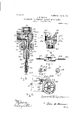
The invention consists of certain novel features shown in simple embodiments in the accompanying drawings, forming a part of this specification, in which Figure 1 is a sectional elevation of the re-.
ceptacle or chamber. Fig. 2 is an end elevation of the same. Fig. 3 is a sectional elevation of the snifting or quick-acting controlling-valve mechanism. Fig. 4 is a sectional plan of the plug-casing, taken on the line 1 2 in Fig. 2, the cylindrical plug being removed. Fig. 5 is an elevation of the apertured cylindrical discharge-plug and its shafts or spindles. Fig. 6 is an end elevation of the plug, showing the snifting-valve-operating lever. Fig. 7 is an end elevation of the plug, showing the spindle for hand operation thereof. Fig; 8 is a part elevation of the receptacle and the float-operating partly-toothed wheel and its holding-pawl. Fig. 9 is a part elevation of the snifting valve bonnet arranged for steam connection. Fig. 10 is a sectional elevation of the snifting controlling-valve adapted to use steam or compressed air to blow out the receptacle when it is-located below the sewer or point of discharge.
In the drawings like reference-numerals indicate similar parts in all the views.
1 is the receiving chamber or receptacle, provided with a cover 1*, which is rendered removable by the stud bolts and nuts 1 2 is the bottom of the receptacle 1, which has an inclination toward the inlet 3 and the inlet non-return valve 3, the latter being placed at or near the upper part of the receptacle 1, as shown in Fig. 1, and adapted to deliver the water and oil from the separator or extractor to the receptacle. The inlet-valve 5 is usually provided with a suitable strainer to prevent sand and other particles from entering the receptacle and interfering with the proper closure of the valve.
4. is the discharge end of the receptacle and has preferably a more or less angle, so that its upper portion extends outwardly, as shown. The end 4: has an opening 4 near the bottom 2 of the chamberl, over which is exteriorly placed the plug-casing 5 and secured by means of the bolts 5 upon the flange 5 6 is a divergent discharge-cavity in the plugcasing 5, which corresponds to the area of the opening or aperture 1 in the end 4 of the receptacle, and its object being to allow for the angular movement of the float-stem, as shown by the dotted lines in Fig. 1.
7 is the plug-seat formed at the narrowest portion of the cavity 6 and terminating with the shoulder 8, thus allowing a bearing for the plug 10 on the upper and lower part of its circumference, Figs. 1 and 4.
8 is a screwed end on the casing 5 for connection with the discharge non-return valve 9, normally held shut by the atmospheric pressure, which is in turn connected to a suitable outlet-pipe 9.
10 is the cylindrical plug and is provided with a discharge-aperture 10, into which the hollow float-stem 11 is secured by screw means to the sleeve 12, placed at a tangent to the hollow float 13 and removably fitted thereto by the union 14c. The float 13 is provided with perforations 13, Fig. 1, for the water and oil to enter and be discharged through the stem 11, and are placed at an angle so that when the float is elevated by the liquid-level in the receptacle the perforations will be in an ap proximate horizontal position or as indicated by the dotted lines in Fig. 1. The plug is provided with spindles and 15, and are capable of being removed at will by means of the nuts 17.
18 is a lever secured to the square end 18 of the plug-spindle 15, Fig. 5, and transmits motion to the snifting-valve by means of the connecting-rod 19, having a rib 19 upon one of its sides to prevent flexure. The rod 19 is provided with an offset or bracket 20, placed at right angles to it, through which passes the lower or screwed portion 21 of the sniftingvalve stem 21.
22 is the snifting or controlling valve, and 22, Fig. 3, is a chamber formed by the valvecasing. The construction and operation of the snifting-valve will be more fully explained hereinafter.
23 is an opening or pipe from the interior of the receptacle 1 to the snifting-valve, which effects a connection to a part of the separator in constant communication with the condenser or above the water-line in the extractor. The communication between the connection 23 and the equalizing-pipe 24 is controlled by certain valves, which will be more fully pointed out hereinafter.
25 is a spring encompassing the sniftingvalve spindle 21 atits threaded portion 21. The spring is placed above the offset 20, as
shown in Fig. 2, and its compression is regulated by the nut 25, so as to act as a cushion to bring the float 13 quietly at rest upon the bottom 2 of the receptacle when discharging.
26 is a spring encircling the stem 21, Figs. 1, 2, and 3, below the bracket or offset 20 and is for the purpose of overcoming the atmospheric pressure acting upon the puppetvalve of the snifting mechanism,which quickly pulls it from its seat. The compression of the spring 26 is regulated and the adjustments retained by means of the nuts 26 in Fig. 2.
27 is a hand-wheel secured upon the end of the plug-spindle 15, Figs. 5 and 6, and is pro vided with ratchet-teeth 28 for engagement with the pawl 29, supported by a pin 29, and is normally held from contact with the teeth by the spring 30. The spring 30 is secured at one end to a pin 29, passing through it, and the nut or washer 29, as shown at 29 the other end of the spring being secured to the pawl, as at 30.
The object of the wheel is to operate the float 13 from the exterior of the receptacle, also to elevate the float a certain distance from the bottom 2 and to hold it in that position by the pawl 29, so that the valve 22 is open to the condenser when the apparatus is first placed in position. When thereceptacle fills, the buoyancy of the float loosens the pawl 29,
which is kept in contact with the teeth 28 by the weight of the float and its stem, and therefore becomes instantly disengaged by the spring from the teeth when sufficientliquid has entered the receptacle to slightly increase the elevation of the float. As the liquid does not fall below a certain level, as in Fig. 1, the necessity of filling the receptacle when itis first set up for operation is avoided, and the pawl 29 is therefore out of service except for the purpose of cleaning.
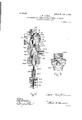
Referring to Fig. 3, 22 is the snifting-valve casing forming the chamber 22 at the termination of the connections 31 and 32, which also correspond to the pipes shown at 23 and 24, respectively, in Fig. 1.
The object of the equalizing-pipe 24 is to afford a passage for the air which may leak into the chamber or receptacle 1 in addition to the exhaustion thereof by the pipe, so as not to interfere with the liquid entering the receptacle through the opening or pipe 3.
33 is the puppet snifting-valve, normally held away from the seat 34 and opening the connection 32 to the condenser, though in Fig. 3 the valve is shown closed to the vacuum, in which position the receptacle is being discharged. The valve 33 is beveled or rounded, as at 34, to fit into the seat 34, which is correspondingly beveled in order to form a tight connection between it and the valve.
34 is a disk-shaped upper portion formed with the valve 33, its object. being to delay the full opening from the condenser after the beveled portion 34 has left the seat 34, the disk portion 34 being of a slightly-smaller diameter than the valve-seat opening.
The valve 33 is provided with wings 35, which are long enough to afford a guide for the valve until a piston, to be described later, has cut off communication with the atmosphere.
36 is a neck or sleeve to which is attached a piston of some expansible material, preferably of rubber, which is held against the collar 39 by the washer 40 and the adjusting-nut 41. Pressure is exerted by means of the nut, which expands the piston, so as to enable it to movably fit air-tight in the sleeve 42 when the valve 33 leaves its seat.
43 is a beveled upper portion of the sleeve 42 to more readily cause the piston to enter it.
44 is an annular clamping-flange on the sleeve 42 in order to secure it at the proper distance in the chamber 22 by means of the clamping nut or ring 44.
45 is a bonnet portion of the sleeve 42 and is provided with suitable perforations 46 to enable the atmospheric pressure to flow into the chamber 22 and therefore into the receptacle 1 when the valve 33 is seated, as in Fig. 3.
47, Fig. 2, represents connections for the water-gage 48.
49 is a drain-opening.
is a combined pressure and vacuum gage,
51 being a pipe from the point of connection 52 onthe cover 1 to the gage.
As shown in Fig. 3, the stem 21 is screwed into the sleeve 36, as indicated by dotted lines.
I will now describe my invention as equipped with the snifting mechanism shown in Fig. 3. The pressure-connected snifting-valve will be described hereinafter.
As already described, after the apparatus is connected to the oil-separator or vacuum device it is necessary to move the wheel 27 to the right and cause the pawl 29 to engage a tooth thereof in order to hold the float a certain distance from the bottom of the receptacle, which causes the valve 33 to be open, and thus produces a vacuum within the receptacle, 1 and at the same time excluding the atmosphere by means of the piston 38, which enters the sleeve 42 simultaneously with the opening of the valve 33. After the float has risen to the top of the receptacle, as shown by dotted lines in Fig. 1, it will fill and settle to the bottom, as in Fig. 1, thereby closing communication with the condenser by means of the valve 33 and opening the interior of the receptacle to the atmosphere, which instantly closes the inle t-valve 3 and when this takes place the outlet-valve 9 will open and the water or other liquid will flow from the receptacle through the stem 11 and the plug 10 by gravity until the liquid-level has fallen to about the height indicated in Fig. 1. At this point the float will empty through its steam causing it to rise its buoyancy, which will compress the spring 26 to a proper degree to enable it to overcome the atmospheric pressure and quickly pull the valve 33 from its seat. The receptacle will then proceed to fill. The piston 38 having a smaller area than the valve, it will not offer the same resistance to the spring when the vacuum is established as the valve when it is closed. As already described, when the valve 33 opens it causes the piston 38 to cut off communication with the atmosphere, in which instance the liquid matter will flow into the inlet-valve 3 the outlet-valve 9 being held shut by the atmos- 5 pheric pressure.
Referring to Fig. 10, in which is shown the snifting,equalizing,or controlling valve mechanism adapted to discharge the receptacle by steam or compressed-air pressure when it is located below the point of discharge-for instance, in large buildings having the steam plant located from ten to twenty feet below the sewer-pipe line, in which case my invention would not be adapted for such use unless it was provided with a pressure connection to blow out the receptacle or a pump attached to the discharge-outlet when the liquid can- The snifting-valve is provided with a cylindrical piston or plug 53, which is a part of the spindle 21 and is held against the sleeve 36 of the valve 33 at the joint 53, by which they may be detached.
The piston 53 is connected to the valve-stem enlargement 54 by the spindle portion 5 1. The piston 53, the stem enlargement 54:, the upper stem portion 54, and the stem 21 are preferably in one piece. The piston 53 and the cylindrical enlargement 54. are of equal diameters for the purpose of balancing them when the valve 33 is open to the condenser. 55 is a plug-casing having a screwed portion 55 for attachment to the main valve-casing 22 and forms a cylindrical or annular bevelended passage, as at 56 and 56 to be opened and closed by the piston 53. The cavity 57 forms a passage for the steam or compressed air from the aperture 57 and the pipe 57 attached to a suitable pressure-supply. 58 is packing material compressed to a proper degree to render the stem enlargement 5 L steam and air tight by means of the gland 58 and the clamp-nut 58 In using the steam injection an excess of pressure within the receptacle 1 is relieved by the safety-valve 59 in Fig. 1. The operation of the mechanism described is precisely the same as that of the valve shown in Fig. 3, with the exception that steam or compressed air is being admitted into the receptacle instead of the atmosphere when discharging its contents, as in the position shown in Fig. 10, until the valve 33 leaves its seat 34: and closes the steam inlet through the cavity or passage 56 and opens the receptacle to the vacuum.
I am not confined to the exact details of construction shown, as I may make such modifications as may be deemed advisable without departing t'rom the subject-matter claimed.
Having described my invention, what I claim, and desire to secure by Letters Patent, 1s-
1. A vacuum-trap comprising a casing having a pressure-controlling device for admitting a fluid under pressure into the casinga vacuum-controlling device for exhausting the casing of pressure, and mechanism controlling the said devices to alternately connect the casing with a pressure-supply and a vacuum apparatus.
2. A vacuum-trap comprising a casing having an inlet and a discharge, a pressure-controlling device for admitting a fluid under pressure into the said casing, a vacuum-controlling device for exhausting the casing of pressure,'and a float-controlled mechanism actuated by the rising and falling of the liquid in the said casing and controlling the said devices. v
3. A vacuum-trap comprising a casing having an inlet and a discharge, a pressure-controlling device for admitting a fluid under pressure into the said casing, a vacuum-controlling device for exhausting the casing of pressure, and a float-controlled mechanism actuated by the rising and falling of the liquid in the said casing and controlling the safety devices, to alternately connect the said casing with a pressure-supply and a vacuum apparatus.
4C. In an apparatus of the class described comprising a liquid-receptacle, means for connecting the said receptacle to a vacuum, valve means forming an outlet for the receptacle to the atmosphere, means for alternately closing the said vacuum connection and the outlet, and exterior controlling means for governing the period of opening and closing to the vacuum source and the outlet to the atmosphere; as described.
5. In an apparatus for receiving and discharging liquids from separators and the like comprising a receptacle having a normally open connection to the vacuum and closed to the atmosphere, means for closing the vacuum connection when discharging to the atmosphere and in a reverse order, and float-actuated exterior means connected to the vacuum source and the atmosphere for controlling the said opening and closing of the receptacle to the vacuum and the exterior thereof; as clescribed.
6. In an apparatus of the class described, of a closed receptacle having a normally open inlet connection to a vacuum and liquid source, a normally closed outlet connection to the atmosphere, automatic means for closing the vacuum and liquid connection when the said atmospheric connection is open, means for closing the said connections in a reverse order, means for closing one connection before opening the other, exterior-disposed vacuum and atmospheric-pressure communicating means actuated by the float for controlling the receptacle connections, and pressure means for forcing the receptacle contents to the atmosphere; as described.
7. In an apparatus of the class described comprisingaclosed vacuous receptacle, means for receiving liquids from oil separators and extractors under a vacuum from and discharging the same to the atmosphere, a vacuum-communicating connection to the vacuum source and the liquid, a discharge connection normally closed to the receptacle interior, floatcontrolled. valve means connected to the vacuous-receptacle interior and the atmosphere and governing the said connections, means for opening the receptacle interior to the vacuum during the filling thereof, means for admitting atmospheric pressure to the said receptacle when discharging, and exterior means for causing a discharge of the receptacle independent of the float; as described.
8. In an apparatus of the class described comprising a closed liquid-receptacle having connection to a source of vacuum and the liquid, an outlet connection normally closed by atmospheric pressure, a liquid-level-actuated exteriorly-disposed valve means connected to the vacuum and the atmosphere, means controlled by the said valve for excluding the atmosphere when the receptacle is filling with the liquid, means for admitting the atmosphere when the receptacle is discharging, and automatic means controlled by the float for closing one receptacle connection before another is open; as described.
9. In an apparatus of the class described comprising avacuous receptacle having a normally open vacuum communicating liquid-inlet, an outlet to the exterior of the receptacle normally closed by atmospheric pressure, equalizing means connected to the vacuum source and the receptacle interior, means controlled by the said equalizing means for maintaining a vacuum when the receptacle is filling with the liquid, means controlled by the equalizing means to close the vacuum connection and admit atmospheric air When the receptacle is discharging to the exterior of the said receptacle, liquid-level controlling means for automatically operating the equalizing means and means exterior to the receptacle for actuating the equalizing means independent of the liquid-level in the receptacle; as described.
10. In an apparatus for discharging liquids in oacuo, comprising a closed receptacle having an outlet connection and a normally open vacuum -communicating inlet-valve, a floatcontrolled snifting-valve normally open to the vacuum, means for simultaneously closing the said snifting-valve to the vacuum and opening thereof to the atmosphere; as described.
11. In an apparatus for discharging liquids under a vacuum comprising a vacuum-chamber having inlet and outlet valves normally closed by atmospheric pressure, an exteriorlydisposed snifting-valve having a normal communication with the said chamber and the vacuum source, float controlling means for simultaneously closing the said snifting-valve to the vacuum connection and opening the same to the atmosphere when discharging the chamber, and means for delaying the full opening of the snifting-valve; as described.
12. In an apparatus for discharging liquids in cacao comprising a closed vacuous receptacle, a vacuum-connected inlet-valve normally discharging into the said vacuous receptacle, a discharge-valve normally closed by atmospheric pressure, afloat-actuated controlling-valve normally in communication with the vacuum and the receptacle interior, means for simultaneously closing the said controllingvalve to the vacuum and the receptacle and admitting the atmosphere thereto during a discharge of the liquid, and means for forcing the discharge of the receptacle by pressure; as described.
13. In an apparatus for collecting and discharging liquids under a vacuum comprising a vacuous receiving-chamber having a liquidinlet valve normally open to the said chamber and the vacuum source, means for closing the said inlet-valve when air is admitted to the connected to the vacuum source and the in-* terior of the chamber, means for causing the said controlling-valve to remain open to the vacuum and the chamber during the filling thereof, and means for closing the controlling-valve to the vacuum and admitting air to the chamber during its discharge; as described.
1 1. In an apparatus for discharging accumulated liquids under a vacuum the combination with a normally vacuous receptacle, a vacuumconnected normally open inlet-valve, a normally closed receptacle discharge-valve, a float-controlled normally open angle-valve for connection to the vacuum source and the receptacle interior, means for simultaneously closing the said angle-valve to the vacuum and the said receptacle interior and admitting the atmosphere thereto, means for closing the said inlet-valve to the vacuum and liquid by atmospheric pressure, and means for opening the said discharge-valve by the weight of the liquid for emptying the receptacle when the atmosphere is admitted; as described.
15. In an apparatus for discharging liquids under a vacuum, the combination with a vacuous-closed receptacle, a vacuum-connected normally open inlet-valve, a normally closed discharge-valve, an angle controlling sniftingvalve connected to and normally open to the vacuum and the interior of the receptacle, means for simultaneously closing the said controlling-valve and admitting the atmosphere to the receptacle, float means for regulating the opening and closing of the controllingvalve, and means for closing the vacuum connections of the receptacle by automatic means when discharging; as described.
16. In an apparatus for automatically discharging liquids under a vacuum, comprising a closed chamber having a vacuum-connected liquid-inlet valve, a normally closed outlet- Valve, an opening at one end of the receptacle, a flanged eXteriorly-disposed plug-casinghavin g an inward divergent cavity, a plug-seat centrally located in the said cavity, a float-actuated apertured plug normally oscillating in the seat during changes in the liquid-level in the receptacle, the said plug adapted to rest upon the seat partially on its circumference, a discharge-orifice at the smaller end of the divergent cavity for the said outlet-valve, and
means for keeping the liquid in the receptacle in contact with the outlet-valve until the opening thereof; as described.
17. In an apparatus for discharging liquids in a vacuum, the combination with a closed vacuum-chamber having an inlet and outlet valve connection, an aperture in the said chamber, a plug-casing exteriorly fixed over the said aperture, the said casing having an inwardly-divergent cavity, a raised seat therein, 7
a float-controlled perforated cylindrical plug adapted for rotary movement in the raised seat, means for discharging the chamber through the plug to the-outlet-valve; as described.
18. In an apparatus for discharging liquids in a vacuum, the combination comprising a vacuous receptacle having an inlet connected to the source of liquid and the vacuum, a discharge-valve, a plug-casing disposed upon the exterior of the receptacle, a transversely-disposed partly-cylindrical seat inclosed therein, a cylindrical plug in the seat having a diametrical perforation therethrough, an interiorlydivergent cavity within the said plug-casing on both sides of the plug-seat to the interior of the receptacle and the outlet-valve, a floatconnected stem secured in the said plug perforation, means for causing a, semirotary movement of the plug by the said stem when actuated by the liquid-level in the receptacle, means for effecting a discharge of the liquid through the stem to the outlet-valve and the atmosphere, and means for opening the said outlet-valve by the hydrostatic head of the liquid when a plenum is established in the receptacle; as described.
19. In an apparatus for discharging liquids under a vacuum, the combination with a vacuous liquid-receiving chamber having an inlet and outlet connection, an angle air and vacuum controlling valve, a detachable cover on the said chamber, an eXteriorly-disposed plugcasing connected to the said chamber and outletvalve, a rotary perforated plug seated centrally within thecasing, a hollow dischargestem fitted at one end to the said plug perforation, a perforated float connected to the other end of the stem, means for discharging the chamber and float through the perforations thereof to the outlet, means for maintaining a channel-way for the liquid to the outlet-valve at any inclination of the said floatstem, means for breaking the vacuum in the chamber during a discharge thereof, and means for automatically restoring the vacuous condition in the chamber after the said discharge; as described.
20. In an apparatus for discharging liquids under a vacuum, the combination with a vacuous receptacle having inlet and outlet connection, an eXteriorly-connected flanged partlycylindrical casing upon the said receptacle, a rotary plug provided with an axial spindle on both sides thereof, centrally located in the said casing, the said plug having a diametrical aperture therethrough, a hollow stem secured in the said aperture, an angular perforated float connected to one end of the stem, an angle vacuum and air valve controlling the passage from the vacuum and the interior of the receptacle, a lever on one of the said plugspindles, connecting means from the said lever for controlling the said angle-valve by the float; as described.
21. In an apparatus for receiving and discharging liquids under a vacuum, the combination with a normally closed vacuous receptacle having inlet and outlet connection, an outside connected flanged plug-casing having the said outlet-valve thereon, a rotary apertured spindle-provided plug centrally disposed within the said casing, a hollow stem fixed at one end to the plug, a hollow liquid-receiving discharge-float attached to the said stem at a tangent thereof, the said float having perforations placed at an angle and adapted to assume an approximate horizontal position when elevated, an angle valve connected to the source of vacuum and the interior of the receptacle, an arm on one of the plug-spindles, means for operating the angle-valve by the said arm, and a wheel on the other plug-spindle for manually raising and lowering the float from the exterior of the receptacle; as described.
22. In an apparatus for discharging liquids in a vacuum, the combination with a collecting vacuous chamber having inlet and outlet valves, an outside connected flanged plug-casing, a rotary movable perforated plug having axial spindles on both ends thereof working air-tight in the casing, aseries of compressionnut stuffing-boxes on the casing for the said spindles, an angular perforated hollow float, a hollow discharging-stem connected to the said float and plug, a lever on one of the said plug-spindles, an angle-valve controlling the opening to the source of vacuum and the interior of the chamber, an operating-stem for opening and closing the angle-valve connections, a connecting-rod having a perforated offset end at right angles to the rod, means for yieldably connecting the said angle-valve spindle to the said rod and through the offset portion, means for opening the said anglevalve to the vacuum by the said yieldableconnection and the connecting-rod, a ratchettoothed hand-wheel on one of the plug-spindles, a spring-pressed pawl engaging with the teeth of the said wheel, means for operating the float from the exterior of the chamber, means for holding the float and stem with the attached mechanism at any point by the said wheel and pawl, and means for disengaging the float and stem by the pawl and spring thereof through the buoyancy of the inclosed float; as described.
.23. In an apparatus for discharging liquids in cacao, the combination with a vacuous receptacle having inlet and outlet connection,
an exteriorly-disposed plug-casing attached thereto, a rotary perforated plug having spindles thereon and seated in the said casing, a stem connected at one of its ends to the plug, a hollow float having angular perforations connected to the other end of the stem, an angle combined airinlet and vacuum cut-off valve for the said receptacle, a partly-threaded working spindle for the angle-valve, an
operating-lever on one of the plug-spindles, a connecting-rod having an apertured bracket pivoted to the said lever and resiliently connected to the angle-valve, a spring encompassing the said spindle of the angle-valve below the said bracket, means for opening the receptacle interior to the vacuum against the pressure of the atmosphere bythe said spring and connecting-rod, a series of adjusting and locking nuts for regulating the spring compression, a bufler-spring encircling the said angle-valve spindle above the connecting-rod bracket, and means for cushioning the impact of the float upon the bottom of the receptacle by the said buffer-spring; as described.
v 24:. In an apparatus for receiving and discharging liquids c'n cacao, the combination with a vacuous receptacle having inlet and outlet connection for the liquid, an angle snifting-valve comprising a valve-casing provided with a connection to the vacuum and a connection to the interior of the receptacle, a bonnet having an inner hollow cylindrical portion and an outer rounded end perforated air-inlet portion, a partly-threaded stem for float-operating the valve mechanism, a beveled valve-seat, a bevel flanged puppet-valve screw-connected to the inner part of the valvestem, a threaded sleeve forming a part of the said puppet-valve, an expansible piston movably closing the bore of the hollow cylindrical bonnet portion when the puppet-valve is unseated for communication with the vacuum, a fixed and movable collar on the said puppetvalve sleeve, screw-and-nut means for compressing the collars'to expand the piston to fill the bore of the cylindrical or sleeved bonnet portion, connecting-rod-actuated spring means for simultaneously unseating the said puppet-valve against atmospheric pressure and closing the said cylindrical bonnet portion to exclude the atmosphere as described.
25. In an apparatus for discharging liquids in mono, the combination of a vacuous receptacle having inlet and outlet connection, an angle controlling-valve comprising a valvecasing having connection to the vacuum and the interior of the receptacle at right angles to each other, a partly-threaded valve-stem a beveled valve-seat in the said valve-casing, a convex-flange winged puppet-valve opening to the said receptacle interior and the vacuum, a threaded sleeve portion on the said puppetvalve, a bearing-collar on the sleeve, an expansible perforatedpiston encircling thevalvestem, a nut-adjusted collar on the said valvestem, means for compressing the-said piston by the collar, a nut-secured interiorly-sleeved bonnet on the said valve-casing, means for causing a sliding closure of the said sleeve by the piston when the puppet-valve is unseated, a perforated outer portion of the said bonnet, means for drawing air through the said perforations to the interior of the receptacle when the puppetvalve is seated, and spring means for the quick opening of the said puppet-valve against the atmospheric pressure; as described.
26. In an apparatus for discharging liquids in cacao, the combination of a vacuous receptacle having inlet and outlet connection, a controlling-valve comprising a valve-casing, a vacuum connection and a connection to the said receptacle interior, a float-operated stem, a tapering valve-seat, a convex-flanged puppet-valve secured to the said stem, a threaded sleeve on the said puppet-valve, a piston enlargement on the valve-stem, a plug removably fitted to the said valve-casing and provided with a pressure-chamber, a cylindrical bore in the said plug for the piston movement, a balancing cylindrical enlargement on the lower end of the valve-stem and fitting air and steam tight in the plug, a compressed-air and steam inlet in the said plug, means for causing a pressure to enter the receptacle when the puppet-valve is seated for discharging its contents, and means for causing the piston to close the said cylindrical bore when the puppet-valve is open, to exclude the pressure; as
described.
27. In an apparatus for discharging liquids in 'UCbC'LLO, the combination with a vacuous receptacle having inlet and outlet connection, of an angle control-and shifting valve comprising a valve-casing having a vacuum and a receptacle connection, a float-operated spindle, a plug in the said casing having a cylindrical bore and a pressure-chamber, a perforation in the plug for admitting pressure therein and to the receptacle, a beveled flanged puppet-valve normally open to the vacuum,
apiston slidably fitting in the said bore, means for simultaneously closing the said puppetvalve and admitting pressure into the receptacle to discharge its contents, means for closing the said bore by the piston when the puppet-valve is open to the vacuum and the interior of the receptacle, means for releasing an excess of pressure in the receptacle, and spring means for resiliently connecting the said puppet-valve, piston and the spindle to the float mechanism; as described.
In testimony whereof I have hereunto aifixed my signature in the presence of two witnesses.
JARARD W. LYTTON.
, Witnesses:
J ETHRO PEEK, ROBERT C. IRWIN.
Priority Applications (1)
| Application Number | Priority Date | Filing Date | Title |
|---|---|---|---|
| US1904230393 US809385A (en) | 1904-10-28 | 1904-10-28 | Apparatus for discharging liquids in vacuo. |
Applications Claiming Priority (1)
| Application Number | Priority Date | Filing Date | Title |
|---|---|---|---|
| US1904230393 US809385A (en) | 1904-10-28 | 1904-10-28 | Apparatus for discharging liquids in vacuo. |
Publications (1)
| Publication Number | Publication Date |
|---|---|
| US809385A true US809385A (en) | 1906-01-09 |
Family
ID=2877866
Family Applications (1)
| Application Number | Title | Priority Date | Filing Date |
|---|---|---|---|
| US1904230393 Expired - Lifetime US809385A (en) | 1904-10-28 | 1904-10-28 | Apparatus for discharging liquids in vacuo. |
Country Status (1)
| Country | Link |
|---|---|
| US (1) | US809385A (en) |
-
1904
- 1904-10-28 US US1904230393 patent/US809385A/en not_active Expired - Lifetime
Similar Documents
| Publication | Publication Date | Title |
|---|---|---|
| US1779319A (en) | Sewage-ejecting mechanism | |
| US3520321A (en) | Venting valve for a beverage filler | |
| US809385A (en) | Apparatus for discharging liquids in vacuo. | |
| US2399111A (en) | Trap | |
| US4025236A (en) | Apparatus for returning condensate | |
| US1096788A (en) | Flushing apparatus. | |
| US1157583A (en) | Multiplier of efficiency for float apparatus. | |
| US674696A (en) | Water-supply valve. | |
| US598386A (en) | Air-valve for water pipe-lines | |
| US2564548A (en) | Liquid piston air compressor | |
| US2582105A (en) | Device for shutting off gases from pipe lines | |
| US1386301A (en) | Apparatus for transferring liquids | |
| US477381A (en) | Air-compressor | |
| US625904A (en) | The nqrftts peters co | |
| US396405A (en) | Automatic compressed-air water-elevator | |
| US1200764A (en) | Beer-dispensing apparatus. | |
| US571621A (en) | Hydraulic engine | |
| US555701A (en) | Steam separator and trap | |
| US2378748A (en) | Steam trap | |
| US1316843A (en) | Return-trap | |
| US708996A (en) | Steam-trap. | |
| US862295A (en) | Steam-trap. | |
| US158593A (en) | Improvement in faucets | |
| US658728A (en) | Automatic gravity boiler-feeder. | |
| US719028A (en) | Steam-trap. |