US809371A - Voting-machine. - Google Patents
Voting-machine. Download PDFInfo
- Publication number
- US809371A US809371A US24203705A US1905242037A US809371A US 809371 A US809371 A US 809371A US 24203705 A US24203705 A US 24203705A US 1905242037 A US1905242037 A US 1905242037A US 809371 A US809371 A US 809371A
- Authority
- US
- United States
- Prior art keywords
- voting
- lever
- machine
- tube
- actuators
- Prior art date
- Legal status (The legal status is an assumption and is not a legal conclusion. Google has not performed a legal analysis and makes no representation as to the accuracy of the status listed.)
- Expired - Lifetime
Links
- 230000007246 mechanism Effects 0.000 description 5
- 230000005484 gravity Effects 0.000 description 2
- 238000005266 casting Methods 0.000 description 1
- 238000010276 construction Methods 0.000 description 1
- 230000000881 depressing effect Effects 0.000 description 1
- 230000003028 elevating effect Effects 0.000 description 1
- 239000000463 material Substances 0.000 description 1
- 239000002184 metal Substances 0.000 description 1
- 230000004048 modification Effects 0.000 description 1
- 238000012986 modification Methods 0.000 description 1
- 230000010355 oscillation Effects 0.000 description 1
- 230000000630 rising effect Effects 0.000 description 1
Images
Classifications
-
- G—PHYSICS
- G07—CHECKING-DEVICES
- G07C—TIME OR ATTENDANCE REGISTERS; REGISTERING OR INDICATING THE WORKING OF MACHINES; GENERATING RANDOM NUMBERS; VOTING OR LOTTERY APPARATUS; ARRANGEMENTS, SYSTEMS OR APPARATUS FOR CHECKING NOT PROVIDED FOR ELSEWHERE
- G07C13/00—Voting apparatus
Definitions
- A is the bottom plate, having an annular Be it known that I, ELIZA A. HARRINGTON, ring or flange A cast thereon. a citizen of the United States, residing in A" is an inwardly-inclined or conical ring 55 Lyndhurst, in the county of Bergen and State forming a deck having at the outer edge a de- 5 of New Jersey, executrix of the last will and pending flange or ring A of the same diamtestarnent of CHARLES F. HARRINGTON, deeter as the ring A, and on the inner edge is ceased, late a citizen of the United States, dean upwardly-extending short flange of less clare that the said CHARLES E.
- HARRINGTON diameter above which, but separated there- 60 did invent a certain new and useful Improvefrom by a narrow annular slot (0, is a cylin- IO ment in Voting-Machines, of which the foldrical ring A.
- a second inclined deck A lowing is a specification. has a downwardly-extending flange A of the Theinvention relates to that class of votingsame diameter as A and an upturned short machines in which the registering mechanisms flange A of less diameter separated by asec- 65 are operated by actuators arranged to be ond annular slot c from a flange A on the I5 moved into operable relation with such mechthird deck A having on its inner edge a anisms.
- a machine of this character is shown short flange A separated by a slot a" from a and described in an application for Letters depending flange A on the outer edge of the Patent of the United States by the same intop plate A
- the top plate carries an annductor, filed October 10, 1904, Serial No. lar flange or fence A cast thereon.
- a vertical shaft B extends axially of the more particularly to means for registering or casing and is supported therein by means (not receiving ballots for independent candidates shown) with liberty to partially rotate. for oflice whose names do not appear on any Through the annular slot (0 projects the end 7 5 of the party tickets as candidates for such of an actuator C, forming one of a series 2 5 oflice adapted for service with the machine loosely mounted on the shaft and adapted to described in such application. be swunghorizontally. Only one of the series The object of the invention is to provide is shown. Itis preferably of sheet metal and simple, easily-operated,and reliable mechanconsists of flat horizontal portion C, through 0 ism for receiving such independent ballots. which the shaft B extends, and a vertical The invention consists in certain novel feaouter portion having two arms C" and C, one
- Fig. 2 is a side view, partly in to be arranged radially on the decks A A in vertical section, showing theindependent votgroups corresponding to the offices to be filled 5 ing mechanism on a larger scale.
- Fig. 3 is a and that the actuators may be swung by the corresponding elevation at a right angle to finger-pieces into line with any name selected.
- G is a sleeve loosely encircling the upper Similar letters of reference indicate the portion of the shaft B and extending through same parts in all the figures.
- the top plate A within the fence A The 100
- the casing in the form of a circular turret sleeve has an annular groove g on its exterior,
- each arm G From the outer end of each arm G hangs a rod 'G, supporting a ring G near the bottom of the casing and a similar ring G at a higher level.
- the rings carry counters F, each having an operating star-wheel F, one for each name on the corresponding deck, and at suitable intervals, preferably one for each oflice, means for actuating an independent ballot-receiving mechanism.
- the latter consists of a plate H, attached to the deck, having a flattened tube or chute H extending downwardly from a slot 7t and terminating within the casing.
- the lower end of the tube is normally closed by a swinging gate H, held in position by gravity, aided, if necessary, by a spring H and supported on a pivot H, set in a lug on the upper portion of the tube.
- H is a lever fulerumed in a support H, secured to the supporting-ring G and having a tail H occupying the same relative position as one of the star-wheels and of about the same thickness.
- To the upturned opposite end of the lever H is pivoted one end of a link H the other end of which is pivoted to the gate H at H.
- the gate uncovers the lower end of the tube H and permits a ballot, preferably in the form of aslip of cardboard upon which the voter has written the name selected, to pass through the tube and fall into the receptacle H from which at the close of the polls the accumulated ballots for the candid ates for that oflice receiving,independent votes may be removed, sorted, and counted.
- the lowering of the rings G G11 permits the gate to close by gravity or the force of the spring H or both, ready to receive another ballot, the return movement being arrested by the lower edge of the lever H strikinga horizontal portion H of the support H.
- the opening through the tube should be only suflicient to receive a single ballot, which, as above stated, may be of thick cardboard or may be of thinner material adapted to be received in any suitable carrier of a thickness to match the tube.
- a cylindrical casing having an annular slot therein, actuators radially mounted in said casing and each having a portion projecting through said slot whereby it may be swung horizontally, a tube extending from the exterior of said casing to the interior and adapted to receive a ballot, a swinging gate normally closing the lower end of said tube, a support adapted to be moved vertically within said casing, a lever carried by said support, a link from one end of said lever to said gate, the other end of said lever arranged when moved vertically with said support, to contact with one of said actuators presented in its path, and thereby move said gate to open said tube.
Landscapes
- Physics & Mathematics (AREA)
- General Physics & Mathematics (AREA)
- Refuge Islands, Traffic Blockers, Or Guard Fence (AREA)
Description
No. 809,371. PATENTED JAN. 9, 1906. G. F. HARRINGTON, DBOD.
B. A. HARRINGTON, EXEGUTRIX.
VOTING MAGHINE.
APPLIGATIONTILED JAN. 20, 1905.
1 UNITED STATES PATENT OFFICE.
ELIZA A. HARRINGTON, OF LYNDHUEST, NEW JERSEY, EXECUTRIX OF CHARLES F. HARRINGTON, DECEASED, ASSIGNOR TO THE DIAL VOT- ING MACHINE COMPANY, OF LYN DHURST, NEW JERSEY, A CORPORA- TION OF NEW JERSEY.
VOTING-MACHINE.
No. 809,371. Specification of Letters Patent. Patented Jan. 9, 1906. Application filed January 20. 1905. Serial 110.242.08'7.
T who?" it W concern: A is the bottom plate, having an annular Be it known that I, ELIZA A. HARRINGTON, ring or flange A cast thereon. a citizen of the United States, residing in A" is an inwardly-inclined or conical ring 55 Lyndhurst, in the county of Bergen and State forming a deck having at the outer edge a de- 5 of New Jersey, executrix of the last will and pending flange or ring A of the same diamtestarnent of CHARLES F. HARRINGTON, deeter as the ring A, and on the inner edge is ceased, late a citizen of the United States, dean upwardly-extending short flange of less clare that the said CHARLES E. HARRINGTON diameter, above which, but separated there- 60 did invent a certain new and useful Improvefrom by a narrow annular slot (0, is a cylin- IO ment in Voting-Machines, of which the foldrical ring A. A second inclined deck A lowing is a specification. has a downwardly-extending flange A of the Theinvention relates to that class of votingsame diameter as A and an upturned short machines in which the registering mechanisms flange A of less diameter separated by asec- 65 are operated by actuators arranged to be ond annular slot c from a flange A on the I5 moved into operable relation with such mechthird deck A having on its inner edge a anisms. A machine of this character is shown short flange A separated by a slot a" from a and described in an application for Letters depending flange A on the outer edge of the Patent of the United States by the same intop plate A The top plate carries an annuventor, filed October 10, 1904, Serial No. lar flange or fence A cast thereon.
227,800, and the present invention relates A vertical shaft B extends axially of the more particularly to means for registering or casing and is supported therein by means (not receiving ballots for independent candidates shown) with liberty to partially rotate. for oflice whose names do not appear on any Through the annular slot (0 projects the end 7 5 of the party tickets as candidates for such of an actuator C, forming one of a series 2 5 oflice adapted for service with the machine loosely mounted on the shaft and adapted to described in such application. be swunghorizontally. Only one of the series The object of the invention is to provide is shown. Itis preferably of sheet metal and simple, easily-operated,and reliable mechanconsists of flat horizontal portion C, through 0 ism for receiving such independent ballots. which the shaft B extends, and a vertical The invention consists in certain novel feaouter portion having two arms C" and C, one
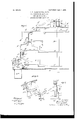
tures and details of construction by which the arm C extending through the slot (4 and terabove objects are attained, to be hereinafter minating in a finger-piece C, the other arm described and claimed. C of less length and terminating in a widened 8 5 The accompanying drawings forma part of toe C The upper series of actuators, one
3 5 this specification and show a preferred form of which is shown, (marked 1),) is similarly of the invention. mounted on the shaft at D, and each has a Figure l is a diametrical vertical section finger-piece D and toe D The upper slot {4" through a part of a voting-machine equipped is also provided with a series of actuators. 90
with the invention, certain portions being (Not shown.)
4.0 shown in elevation and certainother portions For the purposes of this description the of the machine being omitted for clearness of names of the candidates may be understood illustration. Fig. 2 is a side view, partly in to be arranged radially on the decks A A in vertical section, showing theindependent votgroups corresponding to the offices to be filled 5 ing mechanism on a larger scale. Fig. 3 is a and that the actuators may be swung by the corresponding elevation at a right angle to finger-pieces into line with any name selected.
the view in the preceding figure. G is a sleeve loosely encircling the upper Similar letters of reference indicate the portion of the shaft B and extending through same parts in all the figures. the top plate A within the fence A The 100 The casing in the form of a circular turret sleeve has an annular groove g on its exterior,
comprises a series of rings or annular castings in which are received the ends of two pins G arranged one above the other and supported G, extending through the skirt of a second by brackets (not shown) formed on each. sliding sleeve G rotating with the shaft, but
free to be raised or lowered thereon by depressing or elevating the free end of an operating-lever Gd, fulcrumed on an antifriction-roller G"on the opposite end of the lever; The latter is engaged with the sliding sleeve G by pins G, screwed into opposite sides of a yoke G forming part of the lever encircling the upper end of the shaft and extending into corresponding holes in the sliding sleeve. The rising and sinking movements of the lever are thus communicated, to the sleeve G and its radial arms Gr without partaking in the partial rotations of the shaft due to horizontal oscillations of the lever.
From the outer end of each arm G hangs a rod 'G, supporting a ring G near the bottom of the casing and a similar ring G at a higher level. The rings carry counters F, each having an operating star-wheel F, one for each name on the corresponding deck, and at suitable intervals, preferably one for each oflice, means for actuating an independent ballot-receiving mechanism. The latter consists of a plate H, attached to the deck, having a flattened tube or chute H extending downwardly from a slot 7t and terminating within the casing. The lower end of the tube is normally closed by a swinging gate H, held in position by gravity, aided, if necessary, by a spring H and supported on a pivot H, set in a lug on the upper portion of the tube.
H is a lever fulerumed in a support H, secured to the supporting-ring G and having a tail H occupying the same relative position as one of the star-wheels and of about the same thickness. To the upturned opposite end of the lever H is pivoted one end of a link H the other end of which is pivoted to the gate H at H.
When the sleeve G, with its arms G, is elevated, the rings 6 and G also rise and carry with them all the counters F and levers H. Those that find no actuators in their paths are unaeted upon; but if an actuator be swung to a name to be voted the star-wheel of the counter corresponding to that name will strike that actuator and be moved to register one vote on the counter, as set forth in the aboveidentified application, and if an actuator be swung to the space or symbol for independent voting the tail H" of the correspondinglever H will strike such actuator and be tilted to the position shown in dotted lines in Fig. 2, in which the gate uncovers the lower end of the tube H and permits a ballot, preferably in the form of aslip of cardboard upon which the voter has written the name selected, to pass through the tube and fall into the receptacle H from which at the close of the polls the accumulated ballots for the candid ates for that oflice receiving,independent votes may be removed, sorted, and counted. The lowering of the rings G G11 permits the gate to close by gravity or the force of the spring H or both, ready to receive another ballot, the return movement being arrested by the lower edge of the lever H strikinga horizontal portion H of the support H.
The opening through the tube should be only suflicient to receive a single ballot, which, as above stated, may be of thick cardboard or may be of thinner material adapted to be received in any suitable carrier of a thickness to match the tube.
The mechanisms for setting all the actuators simultaneously to the names on a party ticket or to all the independent symbols or spaces and for resetting the actuators to the original or no-vote positions ready for the next voter are omitted from this application and form part of the subject-matter of the aboveidentifiedapplication for patent in which these and other features are fully shown and described.
Modifications may be made in the forms and proportions of the parts as found necessary or desirable in adapting the independent voting mechanism for service in other forms of voting-machines without departingfrom the principle of the invention or sacrificing its advantages.
Having thus described the invention, what is claimed as new and desired to be secured by Letters Patent, is
In a voting-machine, a cylindrical casing having an annular slot therein, actuators radially mounted in said casing and each having a portion projecting through said slot whereby it may be swung horizontally, a tube extending from the exterior of said casing to the interior and adapted to receive a ballot, a swinging gate normally closing the lower end of said tube, a support adapted to be moved vertically within said casing, a lever carried by said support, a link from one end of said lever to said gate, the other end of said lever arranged when moved vertically with said support, to contact with one of said actuators presented in its path, and thereby move said gate to open said tube.
In testimony whereof I have signed my name to this specification in the presence of two subscribing witnesses.
ELlZA A. HARRIN l" ON, filrccafiriu: of the last will (and testament of 0/11/0106 .F. [liar/Layton, dreamed. Witnesses:
HARRY (J. HARRINGTON, CrninLus R. SEARL'E.
Priority Applications (1)
| Application Number | Priority Date | Filing Date | Title |
|---|---|---|---|
| US24203705A US809371A (en) | 1905-01-20 | 1905-01-20 | Voting-machine. |
Applications Claiming Priority (1)
| Application Number | Priority Date | Filing Date | Title |
|---|---|---|---|
| US24203705A US809371A (en) | 1905-01-20 | 1905-01-20 | Voting-machine. |
Publications (1)
| Publication Number | Publication Date |
|---|---|
| US809371A true US809371A (en) | 1906-01-09 |
Family
ID=2877852
Family Applications (1)
| Application Number | Title | Priority Date | Filing Date |
|---|---|---|---|
| US24203705A Expired - Lifetime US809371A (en) | 1905-01-20 | 1905-01-20 | Voting-machine. |
Country Status (1)
| Country | Link |
|---|---|
| US (1) | US809371A (en) |
-
1905
- 1905-01-20 US US24203705A patent/US809371A/en not_active Expired - Lifetime
Similar Documents
| Publication | Publication Date | Title |
|---|---|---|
| US809371A (en) | Voting-machine. | |
| US783156A (en) | Voting-machine. | |
| US703787A (en) | Voting-machine. | |
| US717297A (en) | Ballot-marker. | |
| US879114A (en) | Voting-machine. | |
| US428679A (en) | Cash indicator and register | |
| US1172548A (en) | Voting-machine. | |
| US672938A (en) | Voting-machine. | |
| US2301908A (en) | Remote control device for automatic phonographs | |
| US434661A (en) | Canceling and registering ballot-box | |
| US991882A (en) | Voting-machine. | |
| US2223328A (en) | Coin controlled mechanism for vending machines | |
| US749446A (en) | Wltne | |
| US828816A (en) | Voting-machine. | |
| US488938A (en) | Kennedy doug an | |
| US943675A (en) | Vending-machine. | |
| US1096156A (en) | Fare-register. | |
| US662897A (en) | Coin-controlled machine. | |
| US624818A (en) | johnson | |
| US650623A (en) | Liquid-dispensing apparatus. | |
| US575292A (en) | Voting machine | |
| US424770A (en) | Coin-released weighing-scales or other coin-actuated mechanism | |
| US526401A (en) | landing f | |
| US918165A (en) | Coin-controlled mechanism. | |
| US813007A (en) | Voting-machine. |