US809356A - Oscillating electric fan. - Google Patents
Oscillating electric fan. Download PDFInfo
- Publication number
- US809356A US809356A US21?37104A US809356DA US809356A US 809356 A US809356 A US 809356A US 809356D A US809356D A US 809356DA US 809356 A US809356 A US 809356A
- Authority
- US
- United States
- Prior art keywords
- fan
- support
- fun
- conductor
- motor
- Prior art date
- Legal status (The legal status is an assumption and is not a legal conclusion. Google has not performed a legal analysis and makes no representation as to the accuracy of the status listed.)
- Expired - Lifetime
Links
- 239000004020 conductor Substances 0.000 description 18
- 230000033001 locomotion Effects 0.000 description 4
- 238000006243 chemical reaction Methods 0.000 description 3
- 230000010355 oscillation Effects 0.000 description 3
- 102000004726 Connectin Human genes 0.000 description 2
- 108010002947 Connectin Proteins 0.000 description 2
- 241001233242 Lontra Species 0.000 description 2
- 208000027418 Wounds and injury Diseases 0.000 description 2
- 235000003642 hunger Nutrition 0.000 description 2
- 241000125205 Anethum Species 0.000 description 1
- 241001236839 Coprinellus disseminatus Species 0.000 description 1
- 101100353161 Drosophila melanogaster prel gene Proteins 0.000 description 1
- 238000010276 construction Methods 0.000 description 1
- 230000006378 damage Effects 0.000 description 1
- 208000014674 injury Diseases 0.000 description 1
- 230000003389 potentiating effect Effects 0.000 description 1
- 230000036647 reaction Effects 0.000 description 1
- 230000001105 regulatory effect Effects 0.000 description 1
Images

Classifications
-
- F—MECHANICAL ENGINEERING; LIGHTING; HEATING; WEAPONS; BLASTING
- F04—POSITIVE - DISPLACEMENT MACHINES FOR LIQUIDS; PUMPS FOR LIQUIDS OR ELASTIC FLUIDS
- F04D—NON-POSITIVE-DISPLACEMENT PUMPS
- F04D25/00—Pumping installations or systems
- F04D25/02—Units comprising pumps and their driving means
- F04D25/08—Units comprising pumps and their driving means the working fluid being air, e.g. for ventilation
- F04D25/10—Units comprising pumps and their driving means the working fluid being air, e.g. for ventilation the unit having provisions for automatically changing direction of output air
- F04D25/105—Units comprising pumps and their driving means the working fluid being air, e.g. for ventilation the unit having provisions for automatically changing direction of output air by changing rotor axis direction, e.g. oscillating fans
Definitions
- the object of my invention is to provide im le and etllelent menne for censuur the onei hn ion of en electric fen, end in eurryiun out my invention I pivotelly support the fnn und embody ineens for resisting rotary movements of the fen ntrueture, whereby sueh resistauu'e resets end causes oseillntions of the fau.
- l eonnect the fm structure with un overhead support b an interposed llexihle eonnection capable o being put under torsion, whereby as the fen turns in one direction the supporting connection will be wound, the rem-tion of which otter momentum dieu ont will euuse the fun to move in the op insite direet iou with holler mult otter ming thenornml point or the point ol equili rium, und so on oseillnting h nck ond forth an the hm hlndes rotnte.
- the invention also comprises the novel details of impmvmnent that. will be more fully hereinafter set forth and then pointed out iu the eluitns.
- l ⁇ is u seetiou on the line .-i .-i ui Fig. 2l. l'ur- 0 in u iletuil of u modified form of sup
- Fig. 7 is n side view llustruting the fon in oue position.
- Fig. is n nitnilnr view snowing u position ol the l'nu during operntion,the renrwnnl tilt of the fun being souwwhnt exnggeruted for illustrution; and
- Fig. tl is u plou vie'w show in# dill'erent positions of the fou during oscl ntlon.
- nntv be mthe form oi' oneor more nora s or strings of slik.
- the mo inentum uequired h v tlu ⁇ lnn us it oseillntes, uml the torsion thereby produeed iu the sup port.
- 'lhe length ol' the support 4 between ttseonueetiou with the fun ond the overheud hunger determines lo soute extent the speed nl' oseillnloll of Ille lull nlltl the dislnliee It eneh side ol the nornntl point-ol equilibrium to whit-h the fun struetnre nmvtnrn.
- lhe hloek or hend ti is shown snpported upon the lufoeket ti, ns hy menus of u sorow 7", wherelilv the hloek ti Vund the support. -l muy heudplsted ns desired i" mtnry direotiou.
- lille lower end ol' the support l is shown eouneeled with thehloek S, ulso prel' ernhly of insulating nl'nterinl, tlntt is eonueeted with the fun or motor-eusiug l, whereh)I the fun is pivotnlly supported to oseilhtl.
- 'lo permit mljuslluent ol' the fun with u-oQpeet to its support -l nud to regulute the t'elutlou of Mieux-iso( the fnn-hlndes tu u horizoutul plnue.
- any liaise conductor 'or wire, and the conductor t2 lnav also he similarly arranged independently of ita association with the flexible support 4, as shown in the drawing.
- Aa a convenient means for connecting the nu port 4 and conductor t2. ⁇ with the shaft 5 ave shown said shaft as split lo itudinally and the ends of the support conductor placed therein, the nut 7 aerving tc squeeze t e members of the shaft 5 u n the en port and conductor.
- Fig. I nave ahown a ditl'erent form of raaotional up rt for thtI fan, hat one aet in ln a manner a milar to that above describet with respect to Fig. l. ln this ease the snprt 4, is pivotally connected with the hanger 3 b means of a universal connection, permitting the fan to oaeillate or swing back and forth aa may bc required.
- the opening 27 in the cup .27 is of sullicientsize to permit the support 4" to swing freely, and tlte hemisphertcal surface of the member serves to permit tbc fan to have universal as well as oscillator)y motion.
- a nut 2n on snplmrt 4' perauts vertical adjnsnucat of the fttn with respect to its su lpott.
- .5. 'l be combination e.' an electric l'uu ha vim.' ⁇ a motor, with a hanger abme thc same, terminals connected with said hanger l'orconuct-tion with line-wires. a tlexiblesup
- n psir of blocks one of which is counected with thc fan.
- n hanger for the other block it flexihlc support connecting said blocks, a coiled conductor surrounding said flexible support and connected with said blocks and in circuit with the fen-motor, and another conductor in circuit with the fanmotor,'sub stantially as described.
- a support for an oscillating electric fan comprising a pair of blocks, a shaft car ried by one block, a flexible support connecting Sind shaft with the other oc sprin connected with said blocks and sur roun ing said su port and a conductor connected with sai shaft and with a contact carried by the opposite block, substantially as described.
- a support for an electric fan compriaing a pair o blocks, a shaft carried by one hloelt, a flexible su port connecting said shaft to the other b ock, a conductor connected with said shatt and leading to the yblocks or connection with the co ductor, substantially as described.
- a support for an oscilla electric fan comprising a pai r of blocks, a aft earri by one block, a fiexible sup rt connect- 55 ing said shaft with the other lock, and a coiled wire connected wit-h said blocks and
Landscapes
- Engineering & Computer Science (AREA)
- Mechanical Engineering (AREA)
- General Engineering & Computer Science (AREA)
- Structures Of Non-Positive Displacement Pumps (AREA)
Description
l0.`809,356. n PATBNTBD JAN. 9, 1906.
H. 8. BROWN.
OSGILLATING ELECTRIC FAN. Armonia: num :nu a1. xm.
L .PATnNrsn'J-AN. o, me
oscILLmNa nLcraIo nu.
APHJGA'HOI HLID JULY I?, 1.04.
u L u ffw si i". aftosa, y p63 UNITED 'STATES :PATENT OFFICE.
Immune at num hunt.
Potent JID.' 9, 1900.
muon nu .my a1. im. solo l. man.
uuwtam il muy mman-n.'
Be it known that I, llrznnnur Smxnrzr Bnowx, e citizen of the United States, residing in New York city, borough of Mlnlmtten, New York, have invented eertnln new end useful Improvements in Oseillnting Electric Fans, of which the following in n peciticetion.
The object of my invention is to provide im le and etllelent menne for censuur the onei hn ion of en electric fen, end in eurryiun out my invention I pivotelly support the fnn und embody ineens for resisting rotary movements of the fen ntrueture, whereby sueh resistauu'e resets end causes oseillntions of the fau. In one form of my invention l eonnect the fm structure with un overhead support b an interposed llexihle eonnection capable o being put under torsion, whereby as the fen turns in one direction the supporting connection will be wound, the rem-tion of which otter momentum dieu ont will euuse the fun to move in the op insite direet iou with holler mult otter ming thenornml point or the point ol equili rium, und so on oseillnting h nck ond forth an the hm hlndes rotnte. l This tohiionnl support muy I,e in the form ol one or more llexlhle strands or strings capuhle of twisting and untwisting in op|umite directions. l
The invention also comprises the novel details of impmvmnent that. will be more fully hereinafter set forth and then pointed out iu the eluitns.
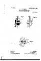
Reference iu to he lntd to the neeonumuyin v drawingmforminf pnrt hereof. wherein igure l nl l. side e evtion of on oseillutiug eleetrie'fnn embodying my invention. Fig. 2 isn vertical section, eulnrgedv, through the fun-sup mrt. Fig. :l is nu eulurged set-tion on the ino 3 il in Fig. Fig. -l is u delnil view showin ein-uit.. t-,onnm-.tious for the lunl'lllftrt. l` is u seetiou on the line .-i .-i ui Fig. 2l. l'ur- 0 in u iletuil of u modified form of sup|mrtjor the fun. Fig. 7 is n side view llustruting the fon in oue position. Fig. is n nitnilnr view snowing u position ol the l'nu during operntion,the renrwnnl tilt of the fun being souwwhnt exnggeruted for illustrution; and Fig. tl is u plou vie'w show in# dill'erent positions of the fou during oscl ntlon. l
' `ln the drawing, in which similar numernls of referentie indiento mal-nsponding ports in the several views, the numernl l indientes n t motor-clung, und -2 the hludes of nuy suit.- l
.the fun n ill prmlnee n resistnneo whieh will eunse reverse motions `or oseillntions of the fun structure. Suid support nntv be mthe form oi' oneor more nora s or strings of slik.
linen. or other suituhle mnterinl eupuhle ol' twisting'nud uut-nisting to orodnee torsion without undue injury. l lind that severnl silk eords or strings plneed loosely side h vside nnd eonneeted.res|uetively,to the hunger und to the fun, enuse the fon to eontinue oseillnting h v rensou of the ur-eurrents propelled from the fun, the vroseopie impulse set up by the rotntiou ol the nrmutnre und hlntles ut nu uugle to the horizontnl. the mo inentum uequired h v tlu` lnn us it oseillntes, uml the torsion thereby produeed iu the sup port. 'lhe length ol' the support 4 between ttseonueetiou with the fun ond the overheud hunger determines lo soute extent the speed nl' oseillnloll of Ille lull nlltl the dislnliee It eneh side ol the nornntl point-ol equilibrium to whit-h the fun struetnre nmvtnrn.
|"or t hepur nose of eon\'enieutl regulnt ing ll|eo|urul|ve eugth of thesupport l thehttler is shown eonneeted ut one end with u shnl'l shown jourunled in u hloek or hend ti, nelernhly ol iusulntiug lnnteriul, .uuid shn .t heiugprovided with n nut 7 for holding it. loeked. lhe hloek or hend ti is shown snpported upon the lufoeket ti, ns hy menus of u sorow 7", wherelilv the hloek ti Vund the support. -l muy heudplsted ns desired i" mtnry direotiou. lille lower end ol' the suport l is shown eouneeled with thehloek S, ulso prel' ernhly of insulating nl'nterinl, tlntt is eonueeted with the fun or motor-eusiug l, whereh)I the fun is pivotnlly supported to oseilhtl. 'lo permit mljuslluent ol' the fun with u-oQpeet to its support -l nud to regulute the t'elutlou of Mieux-iso( the fnn-hlndes tu u horizoutul plnue. l lluve shown menus lorudjustiug Ihel'nn'lnlet'nllylu-ueut `tho support. 4.'. jourunled in lient-ings itt, eurried b v the motor-ensing l nud enguging .n thrended upertut'e in hlm-k S, u thumb-piece ti permitting lo Ihiseud l hove shown userenwrod ti,
tio'
los
fan-motor terminal bv any liaise conductor 'or wire, and the conductor t2 lnav also he similarly arranged independently of ita association with the flexible support 4, as shown in the drawing. Aa a convenient means for connecting the nu port 4 and conductor t2.` with the shaft 5 ave shown said shaft as split lo itudinally and the ends of the support conductor placed therein, the nut 7 aerving tc squeeze t e members of the shaft 5 u n the en port and conductor.
Fig. I nave ahown a ditl'erent form of raaotional up rt for thtI fan, hat one aet in ln a manner a milar to that above describet with respect to Fig. l. ln this ease the snprt 4, is pivotally connected with the hanger 3 b means of a universal connection, permitting the fan to oaeillate or swing back and forth aa may bc required. la thc form chown I have provided antifriction-bearings wherein a hemisphere or the like 25, sweartal to therod-aupport 4", rests upon balls 26, earried by a cup Z, cotmected bv a yoke 28 with the hanger 3, the threaded stellt 28' and nut permitting eonmaetion of the yoke with the hanger, and at 3u is'a coiled spring oonnecttsl at one end with the support and at the other end with the yoke 2n, which spring may be in the nature of n clock-spring norlnallv not under tension. The opening 27 in the cup .27 is of sullicientsize to permit the support 4" to swing freely, and tlte hemisphertcal surface of the member serves to permit tbc fan to have universal as well as oscillator)y motion. A nut 2n on snplmrt 4' perauts vertical adjnsnucat of the fttn with respect to its su lpott. With this form of sup ort for the in thc latter vill o rate in t te tnanner similar to that deecri ed with respect to Fig. l, the twisting and untwisting of spring 30 serving in manner similar to the twisting: and nntwisting of the flexible support 4 to produce the required toraion to cause the continued oscillations of the fan.
My invention is not limited to the particular arrangements and details of construction 'shown and described, as the same may be varied without departing from the spirit thereof.
Having now described my invention, what I claim is l. 'lhc combination, with a fan having its' axis placed at an angle to the vertical and arrttned to deliver a stream ofair in the gcnera direction of said axis, of un electric motor therefor and a suspending device having means for prtalucinfg torsional reaction to the movement of the an about the sat-minding device as a pivot, whereby variations in the current sup lied to the motor serve to maintam oscilla ion of the fan, substantially as described.
2. The combination, with an electric mo- 65 tor-driven fan having its axis placed at an anglo to the vertical and arranged to deliver a stream of air in the general direction of said axis, of a suapcndinpy device having means for producing torsional react ion to tbc |novenient of the fan about the suspending device as a pivot, and means for supplying current to the tnotor. whereby variations in the curn rent serve to maintain oscillation of the fan, substantially as described.
3. The combination, with an electric motor-driven fan having its axis placed at. an angle. to the vertical nml arranged to deliver. a stream of air in the general direct ion of said axis, of a suspending device having means for u'oducin v torsional reaction to the movetnent. of the fan about the suspending device I as n iivot, tlu` axisnf thefan and of the suspcta im.: device being.' in one. vertical plane, and means for supplying current to the taotor, whereby variations in thc current. serve to maintain oscillation of the fan, substantially as described.
' 4. 'l'lte cotnbination of un electric f'uu.lntv
Vim; a motor. with a hanger above the same, a
flexible connection between the hanger attd the fan. means for adjust-ing. the operative len th of said connection between the fan am hanger, uml mcans to convey electrical current to the motor from a source of electrical encre). substantiall) as dcscrila-d.
.5. 'l be combination e.' an electric l'uu ha vim.'` a motor, with a hanger abme thc same, terminals connected with said hanger l'orconuct-tion with line-wires. a tlexiblesup|mrt for` the fan depending from the hanger. conductors connecting said terminals with the mntor, uml means for adjusting the fan laterallv with respect to said support, substantially as described.
ti. The combination of an electric fan. a' horizontally-disposed rod having n block for adjustment. alon v the fan, a hanger above thc fan, and a flexible connection between the hnn'er and the block, embstantiall)I as descri ted.
7. The combination of an electric. fan. a horizontally-tlis|mst\d rod having a block for adjustment along thc fan, a hanger above the fan, a flexible connection between the hanger nml the block, nltd Iucans for adjusting the operativo lctwth of thc support hetwecn the hanger and` the fan, substantially as described.
8. 'lhc combination of tin-electric fan with a block'provided wit-h a shaft, a flexible support connecting said shaftl with the fan, and means for supporting said block. substantiully as described.
tt. 'lhe combination of an electric fan with a flexible support fot' the fun, means for sustaining said support, and a shaft connected with said support for regulating the o )erativc length of the support, substantial v as described.
lt). 'lho combination of an electric fan,
IIC
4. soneriel tor connected with said shaft and in circuit a with the fan-motor, a contact in circuit with seid shaft for connection with a line-wire, uml another conductor connected with the terminal of the motor for connection with the line-wire, substantially as described.
i2. 'l'hc munlvinntion of an electric fan,
with u hloclt.a flexible .support connectin the block with the fnn, s conductor coil around sniel flexible support und in circuit with the fun-motor, and another conductor in circuit with thc fsu-motor, substantially as described.
i3. The combination of an electric fan with u hlock, a flexible support connectin the hloclt with thc fun, a conductor coilei around seid flexible su port and in circuit,
with the fanlnotor, snot er conductor in circuit with thel fan-motor, and means for holding the support and coiled conductor under op|msing twisting strains, substantially as described.
H. 'Ihc combination of an electric tan,
with n psir of blocks, one of which is counected with thc fan. n hanger for the other block, it flexihlc support connecting said blocks, a coiled conductor surrounding said flexible support and connected with said blocks and in circuit with the fen-motor, and another conductor in circuit with the fanmotor,'sub stantially as described.
` l5. support for un oscillating. fan com` l. priaing a pair of blocks, a flexible au l connecting said blocks, and a coiled uotor connected with said bloclte and incloeing i said support, substantially as described. v 16 support for an oscillating fan oomi prising a pair of blocks, a flexib e'au port l connccndg said blocks, a coiled con uctor i connec with said blocks and inclosing said i support, and means for adjusting said coiled conductor and one of the blocks with respect to each other, substantially as described.
isurrounding said support, substantially aa i described.
I8. A support for an oscillating electric fan comprising a pair of blocks, a shaft car ried by one block, a flexible suport connecting sind shaft with the other oc sprin connected with said blocks and sur roun ing said su port and a conductor connected with sai shaft and with a contact carried by the opposite block, substantially as described.
It). A support for an electric fan compriaing a pair o blocks, a shaft carried by one hloelt, a flexible su port connecting said shaft to the other b ock, a conductor connected with said shatt and leading to the yblocks or connection with the co ductor, substantially as described.
HERBERT STANLEY BROWN.
Witnesses:
T. F. Bonnets, M. Hounsosnlan.
other block, s coiled conductor surround said su port, and contacts carriedlloi con- 17. A support for an oscilla electric fan comprising a pai r of blocks, a aft earri by one block, a fiexible sup rt connect- 55 ing said shaft with the other lock, and a coiled wire connected wit-h said blocks and
Applications Claiming Priority (1)
| Application Number | Priority Date | Filing Date | Title |
|---|---|---|---|
| US809356TA |
Publications (1)
| Publication Number | Publication Date |
|---|---|
| US809356A true US809356A (en) | 1906-01-09 |
Family
ID=2877837
Family Applications (1)
| Application Number | Title | Priority Date | Filing Date |
|---|---|---|---|
| US21?37104A Expired - Lifetime US809356A (en) | Oscillating electric fan. |
Country Status (1)
| Country | Link |
|---|---|
| US (1) | US809356A (en) |
Cited By (7)
| Publication number | Priority date | Publication date | Assignee | Title |
|---|---|---|---|---|
| US2496720A (en) * | 1946-09-09 | 1950-02-07 | Sidney J Heiman | Heater fan mounting |
| US2549523A (en) * | 1948-12-16 | 1951-04-17 | Gen Electric | Electric fan |
| US2808198A (en) * | 1956-04-30 | 1957-10-01 | Morrison Hackley | Oscillating fans |
| US3327610A (en) * | 1965-09-13 | 1967-06-27 | Gen Electric | Mounting means for motor-blower unit |
| US4629154A (en) * | 1985-06-20 | 1986-12-16 | Urdan Industries Ltd. | Shock absorber |
| US5368270A (en) * | 1991-12-12 | 1994-11-29 | Wiwczar; Timothy V. | Speaker suspension device |
| US5628488A (en) * | 1994-11-28 | 1997-05-13 | Mann; James A. | Flexible isolation mount |
-
0
- US US21?37104A patent/US809356A/en not_active Expired - Lifetime
Cited By (7)
| Publication number | Priority date | Publication date | Assignee | Title |
|---|---|---|---|---|
| US2496720A (en) * | 1946-09-09 | 1950-02-07 | Sidney J Heiman | Heater fan mounting |
| US2549523A (en) * | 1948-12-16 | 1951-04-17 | Gen Electric | Electric fan |
| US2808198A (en) * | 1956-04-30 | 1957-10-01 | Morrison Hackley | Oscillating fans |
| US3327610A (en) * | 1965-09-13 | 1967-06-27 | Gen Electric | Mounting means for motor-blower unit |
| US4629154A (en) * | 1985-06-20 | 1986-12-16 | Urdan Industries Ltd. | Shock absorber |
| US5368270A (en) * | 1991-12-12 | 1994-11-29 | Wiwczar; Timothy V. | Speaker suspension device |
| US5628488A (en) * | 1994-11-28 | 1997-05-13 | Mann; James A. | Flexible isolation mount |
Similar Documents
| Publication | Publication Date | Title |
|---|---|---|
| US809356A (en) | Oscillating electric fan. | |
| US1108053A (en) | Portable electric fan. | |
| US707842A (en) | Electric fan. | |
| US1142218A (en) | Standard of position for aircraft. | |
| US440665A (en) | Trolley-arm for electric railways | |
| US1015837A (en) | Automatic stabilizer for aeroplanes and the like. | |
| US1100731A (en) | Trolley. | |
| US505396A (en) | Ernest e | |
| US2325908A (en) | Inertia switch | |
| US1082571A (en) | Commutator-brush. | |
| US394037A (en) | Constant upward-pressure contact for overhead conductors | |
| US2715272A (en) | Equipment stand | |
| US576129A (en) | Electrical advertising device | |
| US569772A (en) | Trolley-support for electric railways | |
| US913104A (en) | Undulating-current apparatus. | |
| US533318A (en) | Controller or switch for electric motors | |
| US635812A (en) | Telephone-transmitter arm. | |
| US1033638A (en) | Toy aeroplane. | |
| US598946A (en) | James h | |
| US231362A (en) | Allen w | |
| US445549A (en) | Mast-arm for electric lights | |
| US227863A (en) | Petee wag-neb | |
| US1137239A (en) | Combined electric and pneumatic horn. | |
| US730116A (en) | Trolley-pole. | |
| US751459A (en) | Line-insulator |