US809355A - Centrifugal cream-separator. - Google Patents
Centrifugal cream-separator. Download PDFInfo
- Publication number
- US809355A US809355A US26169905A US1905261699A US809355A US 809355 A US809355 A US 809355A US 26169905 A US26169905 A US 26169905A US 1905261699 A US1905261699 A US 1905261699A US 809355 A US809355 A US 809355A
- Authority
- US
- United States
- Prior art keywords
- cream
- blades
- bowl
- milk
- wall
- Prior art date
- Legal status (The legal status is an assumption and is not a legal conclusion. Google has not performed a legal analysis and makes no representation as to the accuracy of the status listed.)
- Expired - Lifetime
Links
- 239000008267 milk Substances 0.000 description 17
- 210000004080 milk Anatomy 0.000 description 17
- 235000013336 milk Nutrition 0.000 description 17
- 239000006071 cream Substances 0.000 description 15
- 238000005452 bending Methods 0.000 description 1
- 230000009977 dual effect Effects 0.000 description 1
Images
Classifications
-
- B—PERFORMING OPERATIONS; TRANSPORTING
- B04—CENTRIFUGAL APPARATUS OR MACHINES FOR CARRYING-OUT PHYSICAL OR CHEMICAL PROCESSES
- B04B—CENTRIFUGES
- B04B1/00—Centrifuges with rotary bowls provided with solid jackets for separating predominantly liquid mixtures with or without solid particles
- B04B1/04—Centrifuges with rotary bowls provided with solid jackets for separating predominantly liquid mixtures with or without solid particles with inserted separating walls
- B04B1/08—Centrifuges with rotary bowls provided with solid jackets for separating predominantly liquid mixtures with or without solid particles with inserted separating walls of conical shape
Definitions
- This invention relates to centrifugal creamseparators, and particularly to that class that employ vertical division-blades in their separating-bowls.
- Figure 1 is a side view of the division-blades.
- Fig. 2 is an inside view of two adjacent blades.
- Fig. 3 is a crosssection on the line 3 3 of Fig. 1
- Fig. 4 is a vertical section on the line 4 4 of Fig. 3.
- the division blades 1 are represented as curved, so that when they are in place in the bowl they intersect its radial lines, although it is not essential to the invention that they should be so shaped.
- the blades are represented as pivotally attached to one another at their outer ends, as by hinges 2 at their outer edges, so that they can be folded up into cylindrical form and inserted within the bowl, their free ends eX- tending inwardly toward the center of the bowl but other suitable means may be employed for supporting the blades within the bowl in proper relative positions, according to the form of blades adopted and what is required of them.
- Cream-collecting plates 3 cut the radial lines of the bowl adjacent to its wall, but leaving space between them and the wall for milk to circulate.
- cream-collecting plates are represented as integral with the division-blades 1 and are formed by bending said divisionblades inwardly from their curve in the opposite direction from that in which the bowl rotates.
- the cream-collecting plates 3 thus formed lie adjacent to the surface of the bowl when the blades are in place within it and cut the radial lines of the bowl.
- the hinges 2 on the edges of the blades or equivalent pivotal connections are attached to the adjacent blades, respectively, back of the bent portions that constitute the cream-collecting plates 3.
- the blades are shown with ribs that extend diagonally along their inner surfaces from the outer hinged end of the blades upwardly toward the free inner ends. These ribs serve a dual purpose.
- the blades are represented as having three of these ribs each, and the ribs are represented as raised upon the surfaces of the blades by stamping. WVhen the ribs are stamped upon the blades in this manner, they must not lie directly opposite to each other, so that they will nest together, but should be placed up and down alternately along the blades, so that each rib 4 will come at one side or the other of a recess 5, after the manner in which they are arranged in Figs. 2 and 4.
- pins 7 are shown as the locking means, which lie in rings 8 and 9 on the open ends, respectively, of the system of blades.
- This locking device is shown at both the top and the bottom of the blades.
- the unskimmed milk is thrown outward from the center of the bowl by reason of the cen trifugal force developed by the revolution of the bowl in the usual manner, passing through the spaces 10 between the division-blades 1.
- the ribs 4 direct its course.
- the milk reaches the outer ends of the spaces 10, where the cream-collecting plates are placed, most of the cream will have been separated from it; but a considerable amount of cream still remains in the milk.
- This cream is ordinarily lost in separators of this type by passing out of the separator with the milk, and it is the object of this invention to save it. Since the centrifugal force is greatest at this point and the cream-collecting plates 3 cut the radial lines of the bowl, they are well adapted to collect the cream that remains in the milk when it reaches the outer part of the bowl.
- the cream-collecting plates 3 are perforated, as at 11, throughout their length, so that the milk passes from the spaces 10 into the vertical passages 6 around the wall of the bowl. In these passages 6 the cream is separated from the milk by the centrifugal force, the milk passing upward along the wall of the bowl and the cream collecting on the outer surfaces of the cream-collecting plates 3.
- the cream that collects on the inner surfaces of the cream-collecting plates 3 passes over them in the direction opposite to that of rotation and passes onto the adjacent division-blades, respectively, which conduct it back into the bowl.
- cream that 001- lects on the outer surfaces of these creamcollecting plates passes over them in the same direction to the same division-blades, respectively, whence it passes inwardly beneath the edge of the cream-collecting plates and joining the cream from the inner surface of the cream-collecting plates 3 passes inwardly.
- What I claim is 1.
- a centrifugal cream-separator the combination with a rotary bowl, of a series of vertical, cream-collecting plates that inter sect the radial lines of-the bowl adjacent to its wall, leaving space for milk between said plates and said wall, said plates having passages through which the milk can pass to the wall of the bowl; and division-blades adjacent to said cream-collecting plates, adapted to receive the cream from both sides of said plates and to conduct it inwardly.
- a centrifugal cream-separator the combination with a rotary bowl, of a series of division-blades having an ular portions that intersect the radial lines of the bowl adjacent to its wall and leave space for milk between such portions and the wall of thebowl, said blades having passages for the milk to pass to the wall of the bowl from the spaces between said blades, each of said angular por-.
Landscapes
- Food-Manufacturing Devices (AREA)
- Dairy Products (AREA)
Description
No. 809,355. PATENTED JAN. 9, 1906. E. W. BROOMALL.
UBNTRIPUGAL CREAM SEPARATOR.
APPLICATION FILED MAY 22 1905 I NVENTUR= @M'CO. 6M J 74% WITNESEEEI- UNITED. STATES PATENT OFFICE.
CENTRIFUGAL CREAM-SEPARATOR.
Specification of Letters Patent. v
Patented Jan. .9, 1906.
Application filed May 22,1905. Serial No. 261,699.
To all whom it may concern:
Be it known that I, EDGAR W. BROOMALL, a citizen of the United States, and a resident of Rochester, in the county of Monroe and State of New York, have invented certain new and useful Improvements in Centrifugal Cream-Separators, of which the following is a specification,
This invention relates to centrifugal creamseparators, and particularly to that class that employ vertical division-blades in their separating-bowls.
The object of the invention is to. separate from the milk such cream as remains in it when it reaches the wall of the bowl after passing between the blades from the center of the bowl.
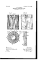
In the drawings, Figure 1 is a side view of the division-blades. Fig. 2 is an inside view of two adjacent blades. Fig. 3 is a crosssection on the line 3 3 of Fig. 1, and Fig. 4 is a vertical section on the line 4 4 of Fig. 3.
In the drawings the division blades 1 are represented as curved, so that when they are in place in the bowl they intersect its radial lines, although it is not essential to the invention that they should be so shaped. The blades are represented as pivotally attached to one another at their outer ends, as by hinges 2 at their outer edges, so that they can be folded up into cylindrical form and inserted within the bowl, their free ends eX- tending inwardly toward the center of the bowl but other suitable means may be employed for supporting the blades within the bowl in proper relative positions, according to the form of blades adopted and what is required of them. Cream-collecting plates 3 cut the radial lines of the bowl adjacent to its wall, but leaving space between them and the wall for milk to circulate. In the drawings these cream-collecting plates are represented as integral with the division-blades 1 and are formed by bending said divisionblades inwardly from their curve in the opposite direction from that in which the bowl rotates. The cream-collecting plates 3 thus formed lie adjacent to the surface of the bowl when the blades are in place within it and cut the radial lines of the bowl. The hinges 2 on the edges of the blades or equivalent pivotal connections are attached to the adjacent blades, respectively, back of the bent portions that constitute the cream-collecting plates 3. The blades are shown with ribs that extend diagonally along their inner surfaces from the outer hinged end of the blades upwardly toward the free inner ends. These ribs serve a dual purpose. They both space the bladesthat is, retain them at their proper distances apart while under centrifugal force to make passages between them for the milk-and they also serve as guides for the cream to conduct it inwardly. In the drawings the blades are represented as having three of these ribs each, and the ribs are represented as raised upon the surfaces of the blades by stamping. WVhen the ribs are stamped upon the blades in this manner, they must not lie directly opposite to each other, so that they will nest together, but should be placed up and down alternately along the blades, so that each rib 4 will come at one side or the other of a recess 5, after the manner in which they are arranged in Figs. 2 and 4.
When the cream-collecting plates 3 are in place within the bowl, which is represented by dotted lines in Fig. 3, vertical compartments 6 are formed between the lines along which the arched cream-collecting plates contact the wall of the bowl. If curved division-blades likethose shown are used and such blades are hinged together and folded up, as shown in Fig. 3, they will expand under the centrifugal force developed by the rapid revolution of the bowl, and the outer endsof blades will engage the wall of the bowl and tend to straighten out at their curved portions 3, so that these will lie against the wall of the bowl, in which case the vertical passages 6 will be eliminated. To prevent this and preserve the vertical passages 6, the cylindrical system of blades is locked together by suitable means when folded up in the manner shown in Fig. 3. In the drawings pins 7 are shown as the locking means, which lie in rings 8 and 9 on the open ends, respectively, of the system of blades. This locking device is shown at both the top and the bottom of the blades. In operation the unskimmed milk is thrown outward from the center of the bowl by reason of the cen trifugal force developed by the revolution of the bowl in the usual manner, passing through the spaces 10 between the division-blades 1. As the cream is separated from the milk and passes inwardly the ribs 4 direct its course. When the milk reaches the outer ends of the spaces 10, where the cream-collecting plates are placed, most of the cream will have been separated from it; but a considerable amount of cream still remains in the milk. This cream is ordinarily lost in separators of this type by passing out of the separator with the milk, and it is the object of this invention to save it. Since the centrifugal force is greatest at this point and the cream-collecting plates 3 cut the radial lines of the bowl, they are well adapted to collect the cream that remains in the milk when it reaches the outer part of the bowl.
The cream-collecting plates 3 are perforated, as at 11, throughout their length, so that the milk passes from the spaces 10 into the vertical passages 6 around the wall of the bowl. In these passages 6 the cream is separated from the milk by the centrifugal force, the milk passing upward along the wall of the bowl and the cream collecting on the outer surfaces of the cream-collecting plates 3. The cream that collects on the inner surfaces of the cream-collecting plates 3 passes over them in the direction opposite to that of rotation and passes onto the adjacent division-blades, respectively, which conduct it back into the bowl. The cream that 001- lects on the outer surfaces of these creamcollecting plates passes over them in the same direction to the same division-blades, respectively, whence it passes inwardly beneath the edge of the cream-collecting plates and joining the cream from the inner surface of the cream-collecting plates 3 passes inwardly.
What I claim is 1. In a centrifugal cream-separator, the combination with a rotary bowl, of a series of vertical, cream-collecting plates that inter sect the radial lines of-the bowl adjacent to its wall, leaving space for milk between said plates and said wall, said plates having passages through which the milk can pass to the wall of the bowl; and division-blades adjacent to said cream-collecting plates, adapted to receive the cream from both sides of said plates and to conduct it inwardly.
2. In a centrifugal cream-separator, the combination with a rotary bowl, of a series of division-blades having an ular portions that intersect the radial lines of the bowl adjacent to its wall and leave space for milk between such portions and the wall of thebowl, said blades having passages for the milk to pass to the wall of the bowl from the spaces between said blades, each of said angular por-.
tions of said blades approaching another blade whereby cream is delivered from both of its sides to such other blade to be conducted inwardly thereby.
3. In a centrifugalcream-separator, the
combination with a rotary bowl, of a series of vertical, cream-collecting plates that intersect the radial lines of the bowl and form a series ofvertical compartments for milk between them and the wall, said plates having passages through which milk can pass to said vertical channels; and divisionblades adja cent to said cream-collecting plates, adapted to receive the cream from both sides of said plates and to conduct it inwardly.
EDGAR W. BROOMALL.
Witnesses:
D. GURNEE, L. THON.
Priority Applications (1)
| Application Number | Priority Date | Filing Date | Title |
|---|---|---|---|
| US26169905A US809355A (en) | 1905-05-22 | 1905-05-22 | Centrifugal cream-separator. |
Applications Claiming Priority (1)
| Application Number | Priority Date | Filing Date | Title |
|---|---|---|---|
| US26169905A US809355A (en) | 1905-05-22 | 1905-05-22 | Centrifugal cream-separator. |
Publications (1)
| Publication Number | Publication Date |
|---|---|
| US809355A true US809355A (en) | 1906-01-09 |
Family
ID=2877836
Family Applications (1)
| Application Number | Title | Priority Date | Filing Date |
|---|---|---|---|
| US26169905A Expired - Lifetime US809355A (en) | 1905-05-22 | 1905-05-22 | Centrifugal cream-separator. |
Country Status (1)
| Country | Link |
|---|---|
| US (1) | US809355A (en) |
-
1905
- 1905-05-22 US US26169905A patent/US809355A/en not_active Expired - Lifetime
Similar Documents
| Publication | Publication Date | Title |
|---|---|---|
| US979182A (en) | Catch-basin cover. | |
| US809355A (en) | Centrifugal cream-separator. | |
| US795424A (en) | Centrifugal cream-separator. | |
| US715493A (en) | Liner for centrifugal cream-separators. | |
| US779099A (en) | Centrifugal cream-separator. | |
| US841925A (en) | Centrifugal separator. | |
| US743428A (en) | Centrifugal separator. | |
| US1002970A (en) | Centrifugal cream-separator. | |
| US786369A (en) | Centrifugal liquid-separator. | |
| US1151686A (en) | Liner for centrifugal liquid-separators. | |
| US759136A (en) | Centrifugal liquid-separator. | |
| US929697A (en) | Liner for centrifugal separators. | |
| US715001A (en) | Centrifugal liquid-separator. | |
| US821554A (en) | Centrifugal cream-separator. | |
| US788752A (en) | Liner for centrifugal separators. | |
| US844244A (en) | Centrifugal cream-separator. | |
| US676410A (en) | Centrifugal liquid-separator. | |
| US892913A (en) | Centrifugal cream-separator. | |
| US855189A (en) | Centrifugal liquid-separator. | |
| US929372A (en) | Cream-separator-bowl liner. | |
| US725868A (en) | Centrifugal separator. | |
| US528941A (en) | Centrifugal cream-separator | |
| US807055A (en) | Centrifugal separator. | |
| US892999A (en) | Liner for centrifugal bowls. | |
| US889350A (en) | Cream-separator. |