US809349A - Grindstone-frame. - Google Patents
Grindstone-frame. Download PDFInfo
- Publication number
- US809349A US809349A US24320705A US1905243207A US809349A US 809349 A US809349 A US 809349A US 24320705 A US24320705 A US 24320705A US 1905243207 A US1905243207 A US 1905243207A US 809349 A US809349 A US 809349A
- Authority
- US
- United States
- Prior art keywords
- standards
- bars
- grindstone
- frame
- bent
- Prior art date
- Legal status (The legal status is an assumption and is not a legal conclusion. Google has not performed a legal analysis and makes no representation as to the accuracy of the status listed.)
- Expired - Lifetime
Links
Images
Classifications
-
- B—PERFORMING OPERATIONS; TRANSPORTING
- B24—GRINDING; POLISHING
- B24B—MACHINES, DEVICES, OR PROCESSES FOR GRINDING OR POLISHING; DRESSING OR CONDITIONING OF ABRADING SURFACES; FEEDING OF GRINDING, POLISHING, OR LAPPING AGENTS
- B24B23/00—Portable grinding machines, e.g. hand-guided; Accessories therefor
- B24B23/02—Portable grinding machines, e.g. hand-guided; Accessories therefor with rotating grinding tools; Accessories therefor
- B24B23/024—Portable grinding machines, e.g. hand-guided; Accessories therefor with rotating grinding tools; Accessories therefor driven by hands or feet
Definitions
- This invention relates to improvements in the construction of frames for grindstones, and the especialiobject is to provide a metal frame of the bicycle type that will furnish a I strong and rigid support for the grindstone and the operator and one that can be readily knocked down and folded into compact form for shipment.
- A represents the re'ar framestandard made from a bar of angle-iron, which is bent to form the two uprights and the cross-bar 0 the latter adapted to lie on the ground and the upper ends of the uprights converging on opposite sides of the stone G.
- Theuprights are connected and stiffened by flat metal straps a, which are preferably crossed, as shown.
- a B represents the front standard, which in all essentials is constructed and shaped like the standard A and provided with integral bottom cross-bar b and with a bracing-strap b The upper ends of the standard are brought near together and are connected by a bolt If.
- the standards A B are connected by the fiat metal bars C D.
- the two bars C are bent to the form shown and have their lower ends bolted to the uprights of the standard B at a point about midway the height of the latter, and their upper ends are bolted to the upper ends of the uprights of the standard A, the stone G being arranged between the upper portions of said bars.
- the barD is bent upon itself, as at d, to form a support for the saddle-seat, which maybe secured thereto in any convenient manner.
- the bar D is arranged between the two bars 0, is riveted or bolted to the latter at d, and its lower ends are bolted to the uprights of the standard A at a point about midway the height of the latter.
- the bolt b also passes through the bar D.
- the bars C and D form two X- frames on opposite sides of the grindstone, which serve to effectively brace the standards, which are set so that they incline toward each other at their upper ends, as shown.
- the bars may be readily folded together on their connectingpivots d thus enabling them to be packed between the two standards in a manner that will be readily apparent.
- a guard g is arranged between the two legs of thebar D and is connected with the bolt 5
- the spindle of the grindstone is journaled in the plates 9 which are bolted to the upper portion of the bars C, and on one end of the spindle is fixed a crank F, which is formed with an angular extension f at its free end, in which an annular groove f is cut to provide a raceway for the bearing-balls, as shown in Fig. 2.
- Plates f are mounted on the extension f, riveted together and furnish a housing for the balls. These plates also furnish a connection for the upper end of the pitman-rod f Extending across the lower portion of the standard A is a rod e on the outer ends of which are pivotally mounted the treadles E.
- treadles are each formed from a flat metal bar, the free end of which is bent to form a loop e of'suitable size and shape to afford a convenient foot-rest.
- the under edge of the treadles is notched, as at 0 to receive the lower hooked end of the pitman f which loosely engages said treadle, thus pro viding an adjustable and detachable connection between the treadles and the pitmanrods.
- the treadles are braced by two angularly-arranged bars e, one end of which is mounted on the rod 6 and the other end is rigidly riveted to the treadle-bar.
- treadles may be disconnected from the standard A by merely removing the rod 6
- the standards are triangular in form with the base resting on the ground, thus securing the maximum strength and bearing for these most important elements in the frame and resisting any tendency to twist or lose their shape.
- the ball-bearing connection between the crank F and the pitman-rods effects an antiirictional engagement which promotes light and easy running.
- two standards each consisting of a single bar of iron bent to form a triangle the base of which is adapted to rest on the ground, said standards arranged with their upper portions inwardly inclined, and means connecting and bracing said standards consisting of bars having their ends bolted to the standards, said bars arranged in X form and pivoted together at their intersecting points.
- two standards each consisting of a single bar of iron bent to form a triangle the base of which is adapted to rest on the ground, and means connecting and bracing said standards consisting of bars having their ends bolted to the standards, said bars arranged in X form and pivoted together at their intersecting points, and one of said bars bent to form a seat-support substantially as described.
- two standards each consisting of a single bar of iron bent to form a triangle the base of which is adapted to rest on the ground, means connecting said standards consisting of bars having their ends bolted to the standards, said bars arranged in X form and pivoted together at their intersecting points, one of said bars bent to form a seat-support and extending on both sides of the frame, and the other bars bent horizontally at their upper ends to form a support on each side of the grindstone.
Landscapes
- Engineering & Computer Science (AREA)
- Mechanical Engineering (AREA)
- Finish Polishing, Edge Sharpening, And Grinding By Specific Grinding Devices (AREA)
Description
N0. 809,349. PATENTED JAN. 9, 1906. G- WIDEMAN.
GRINDSTONE FRAME.
APPLICATION FILED JAN. 30. 1905.
14077755 555 V E/770E 'VUNITED sTArns PATENT OFFICE.
GUSTAVUS WIDEMAN, OF AURORA, ILLINOIS, ASSIGN OR TO THE RICHARDS MANUFACTURING COMPANY, OF AURORA, ILLINOIS, A CORPORATION or ILLINOIS.
GRlNDSTONE-FRAME.
Specification of Letters Patent.
Patented Jan. 9, 1906.
I To all whom itmay concern:
Be it known that I, GUsTAvUs WIDEMAN, a citizenof the United States, residing at Aurora, in the county of Kane and State of Illinois, have invented certain new and useful Improvements in Grindstone-Frames, of which the following is a specification.
This invention relates to improvements in the construction of frames for grindstones, and the especialiobject is to provide a metal frame of the bicycle type that will furnish a I strong and rigid support for the grindstone and the operator and one that can be readily knocked down and folded into compact form for shipment.
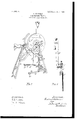
Having other objects of general utility in view, I have produced the grindstone-frame illustrated in the accompanying drawings, in which Figurel is a perspective view of my improved grindstone-frame complete with-the stone in position; and Fig. 2 is a detail, on an enlarged scale, of the crank and pitman-rod connection.
Referring to the drawings in detail, A represents the re'ar framestandard made from a bar of angle-iron, which is bent to form the two uprights and the cross-bar 0 the latter adapted to lie on the ground and the upper ends of the uprights converging on opposite sides of the stone G. Theuprights are connected and stiffened by flat metal straps a, which are preferably crossed, as shown.
a B represents the front standard, which in all essentials is constructed and shaped like the standard A and provided with integral bottom cross-bar b and with a bracing-strap b The upper ends of the standard are brought near together and are connected by a bolt If.
The standards A B are connected by the fiat metal bars C D. The two bars C are bent to the form shown and have their lower ends bolted to the uprights of the standard B at a point about midway the height of the latter, and their upper ends are bolted to the upper ends of the uprights of the standard A, the stone G being arranged between the upper portions of said bars. The barD is bent upon itself, as at d, to form a support for the saddle-seat, which maybe secured thereto in any convenient manner. The bar D is arranged between the two bars 0, is riveted or bolted to the latter at d, and its lower ends are bolted to the uprights of the standard A at a point about midway the height of the latter. The bolt b also passes through the bar D. As arranged, the bars C and D form two X- frames on opposite sides of the grindstone, which serve to effectively brace the standards, which are set so that they incline toward each other at their upper ends, as shown. By removing the various bolts which connect the bars C D with the standards the bars may be readily folded together on their connectingpivots d thus enabling them to be packed between the two standards in a manner that will be readily apparent.
A guard g is arranged between the two legs of thebar D and is connected with the bolt 5 The spindle of the grindstone is journaled in the plates 9 which are bolted to the upper portion of the bars C, and on one end of the spindle is fixed a crank F, which is formed with an angular extension f at its free end, in which an annular groove f is cut to provide a raceway for the bearing-balls, as shown in Fig. 2. Plates f are mounted on the extension f, riveted together and furnish a housing for the balls. These plates also furnish a connection for the upper end of the pitman-rod f Extending across the lower portion of the standard A is a rod e on the outer ends of which are pivotally mounted the treadles E. These treadles are each formed from a flat metal bar, the free end of which is bent to form a loop e of'suitable size and shape to afford a convenient foot-rest. The under edge of the treadles is notched, as at 0 to receive the lower hooked end of the pitman f which loosely engages said treadle, thus pro viding an adjustable and detachable connection between the treadles and the pitmanrods. The treadles are braced by two angularly-arranged bars e, one end of which is mounted on the rod 6 and the other end is rigidly riveted to the treadle-bar. It will be apparent that the treadles may be disconnected from the standard A by merely removing the rod 6 It will be noted that the standards are triangular in form with the base resting on the ground, thus securing the maximum strength and bearing for these most important elements in the frame and resisting any tendency to twist or lose their shape. The ball-bearing connection between the crank F and the pitman-rods effects an antiirictional engagement which promotes light and easy running.
Having thus described my invention, what I claim as new, and desire to secure by Letters Patent, is-
1. In a grindstone-fraine, two standards, each consisting of a single bar of iron bent to form a triangle the base of which is adapted to rest on the ground, said standards arranged with their upper portions inwardly inclined, and means connecting and bracing said standards consisting of bars having their ends bolted to the standards, said bars arranged in X form and pivoted together at their intersecting points.
2. In a grindsto11eframe, two standards each consisting of a single bar of iron bent to form a triangle the base of which is adapted to rest on the ground, and means connecting and bracing said standards consisting of bars having their ends bolted to the standards, said bars arranged in X form and pivoted together at their intersecting points, and one of said bars bent to form a seat-support substantially as described.
3. In a grindstone-frame, two standards, each consisting of a single bar of iron bent to form a triangle the base of which is adapted to rest onthe ground, and means connecting and bracing said standards consisting of the bent bar D, and bars 0, arranged and connected in X form,treadles pivotally connected with one of said standards, pitman-rods detachably connected with said treadles and means connecting said pitman-rods with a grindstone.
4. In a grindstone-frame, two standards, each consisting of a single bar of iron bent to form a triangle the base of which is adapted to rest on the ground, means connecting said standards consisting of bars having their ends bolted to the standards, said bars arranged in X form and pivoted together at their intersecting points, one of said bars bent to form a seat-support and extending on both sides of the frame, and the other bars bent horizontally at their upper ends to form a support on each side of the grindstone.
5. In a grindstone-frame, two triangularshaped standards, means connecting said standards, said means consisting of metal bars bent edgewise near their ends to form horizontal portions, said portions bolted to the standards, and said bars arranged in X form and pivoted together at their points of inter section, a grindstone mounted on said frame, and means for operating said grindstone.
In testimony whereof I aflix my signature in presence of two witnesses.
GUSTAVUS WIDEMAN.
Witnesses:
MERRIGK K. EDWARDS, FRANK M. PRICE.
Priority Applications (1)
| Application Number | Priority Date | Filing Date | Title |
|---|---|---|---|
| US24320705A US809349A (en) | 1905-01-30 | 1905-01-30 | Grindstone-frame. |
Applications Claiming Priority (1)
| Application Number | Priority Date | Filing Date | Title |
|---|---|---|---|
| US24320705A US809349A (en) | 1905-01-30 | 1905-01-30 | Grindstone-frame. |
Publications (1)
| Publication Number | Publication Date |
|---|---|
| US809349A true US809349A (en) | 1906-01-09 |
Family
ID=2877830
Family Applications (1)
| Application Number | Title | Priority Date | Filing Date |
|---|---|---|---|
| US24320705A Expired - Lifetime US809349A (en) | 1905-01-30 | 1905-01-30 | Grindstone-frame. |
Country Status (1)
| Country | Link |
|---|---|
| US (1) | US809349A (en) |
-
1905
- 1905-01-30 US US24320705A patent/US809349A/en not_active Expired - Lifetime
Similar Documents
| Publication | Publication Date | Title |
|---|---|---|
| US809349A (en) | Grindstone-frame. | |
| US311662A (en) | Margaket e | |
| US929207A (en) | Swinging chair. | |
| US571705A (en) | Hand-truck | |
| US755039A (en) | Adjustable and collapsible support. | |
| US1209452A (en) | Multiple-seat unit. | |
| US128332A (en) | Improvement in builders trestles | |
| US1349701A (en) | Teeter-totter | |
| US1128709A (en) | Swing. | |
| US560609A (en) | Swing | |
| US294096A (en) | Drag-saw | |
| US528026A (en) | Pl ace | |
| US568066A (en) | Roof construction | |
| US1125571A (en) | Hand-truck. | |
| US719008A (en) | Folding frame for grinders. | |
| USRE11496E (en) | Child s gradle | |
| US552964A (en) | Trestle | |
| US141741A (en) | Improvement in mechanical powers | |
| US508397A (en) | Hay rake and loader | |
| US770121A (en) | Roundabout. | |
| US135281A (en) | Improvement in rotary churns | |
| US201265A (en) | Improvement in ice-velocipedes | |
| US233420A (en) | David i | |
| US907733A (en) | Swinging chair. | |
| US371856A (en) | John h |