US809348A - Power-hammer. - Google Patents
Power-hammer. Download PDFInfo
- Publication number
- US809348A US809348A US21095004A US1904210950A US809348A US 809348 A US809348 A US 809348A US 21095004 A US21095004 A US 21095004A US 1904210950 A US1904210950 A US 1904210950A US 809348 A US809348 A US 809348A
- Authority
- US
- United States
- Prior art keywords
- hammers
- hammer
- shaft
- disk
- casing
- Prior art date
- Legal status (The legal status is an assumption and is not a legal conclusion. Google has not performed a legal analysis and makes no representation as to the accuracy of the status listed.)
- Expired - Lifetime
Links
- 238000010276 construction Methods 0.000 description 3
- 230000004048 modification Effects 0.000 description 2
- 238000012986 modification Methods 0.000 description 2
- RZVAJINKPMORJF-UHFFFAOYSA-N Acetaminophen Chemical compound CC(=O)NC1=CC=C(O)C=C1 RZVAJINKPMORJF-UHFFFAOYSA-N 0.000 description 1
- DPXHITFUCHFTKR-UHFFFAOYSA-L To-Pro-1 Chemical compound [I-].[I-].S1C2=CC=CC=C2[N+](C)=C1C=C1C2=CC=CC=C2N(CCC[N+](C)(C)C)C=C1 DPXHITFUCHFTKR-UHFFFAOYSA-L 0.000 description 1
- 210000003811 finger Anatomy 0.000 description 1
- 230000001105 regulatory effect Effects 0.000 description 1
- 230000002441 reversible effect Effects 0.000 description 1
- 210000003813 thumb Anatomy 0.000 description 1
Images
Classifications
-
- B—PERFORMING OPERATIONS; TRANSPORTING
- B25—HAND TOOLS; PORTABLE POWER-DRIVEN TOOLS; MANIPULATORS
- B25D—PERCUSSIVE TOOLS
- B25D11/00—Portable percussive tools with electromotor or other motor drive
- B25D11/06—Means for driving the impulse member
- B25D11/066—Means for driving the impulse member using centrifugal or rotary impact elements
- B25D11/068—Means for driving the impulse member using centrifugal or rotary impact elements in which the tool bit or anvil is hit by a rotary impulse member
Definitions
- My invention relates to improvements in power-hammers and the object of my invention is in themain to produce an efficient and compact power-hammer which can be adapted to a great many purposes and which can be conveniently manipulated.
- a further object of my invention is to pro- 1 quiz a comparatively simple device in which I a series of rotating hammers are arranged to 1 successively strike a plunger which can be made to impinge on any suitable tool and to have the hammers and the whole mechanism carried in a convenient casing which is provided with a handle and constructed so that the affair can be easily operated and so that this can be done with safety to the operator and without danger of disorganizing the mechanism.
- Another object of my invention is to construct the device so that the hammers can be instantly thrown into or out of operation.
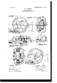
- Figure 1 is a central section taken transversely of the shaft of the device.
- Fig. 2 is a cross-section on the line 2 2 of Fig. 1.
- Fig. 3 is a cross-section on the line 3 3 of Fig. 1.
- Fig. 4 is a broken detail sectional view showing the hammers out of use.
- Fig. 5 is a section similar to that shown in Fig. 2, but illustrating how an electric motor can be conveniently used for operating the device and illustrating also certain modifications of the hammer; and
- Fig. 6 is a cross-section on the line 6 6 of Fig. 5.
- the mechanism is all contained in an inclosed casing 10 of a generally cylindrical shape, which is preferably made in two parts 11, having meeting flanges, and these parts can be fastened together in any customary manner.
- the casing On opposite ends the casing is cen trally thickened to provide bearings 12 for the central shaft 13, and this can be turned in any convenient way.
- a flexible shaft 14 of the usual kind is desirable, and as the casing is provided with a handle grip 1O it can be moved around as desired and directed against any part to be operated on, as will presently appear.
- the shaft 13 carries a pair of parallel disks 15 and 15, which have meeting bosses 16,
- hammers 17 which are pivoted between the disks, as shown at 18, and which have faces or heads 17 projecting beyond the circumference of the disks 15.
- These hammers may be made in many shapes; but I prefer to make them in the form of segments, as in Fig. 1, with the head portion 17 projecting from one radial edge. Any necessary number of these hammers can be employed, and they are arranged to successively strike the head 19 of a plunger 20, which is preferably retracted by a spring 21 and which has a sliding motion limited by the pin 23, which extends through the slot 22 of the plunger.
- This plunger works in the tool-holder 24, which is made, preferably, integral with the casing 10 and which should be on the side opposite the handle 10, so that the tool held in the holder can be conveniently directed.
- This holder 24 is adapted to receive the shank 25 of any suitable tool, the shank in the present instance carrying a riveting-head 26, which fits the hammer for riveting purposes, and it will be seen that the rotation of the shaft 13 will cause the hammers 17 to deliver rapid strokes on the plunger and that these strokes will be communicated to the shank 25.
- the shank might represent the shank of a rock-drill or other instrument.
- the space around the shaft 13 between the disks 15 and 15 is preferably filled by rawhide washers 13 which assist in taking up the clatter of the mechanism.
- T 0 provide for throwing the hammers in and out of gear, I use, preferably, the mechanism shown in Figs. 2 and 3.
- the disk 15 is provided with holes, (shown by dotted lines at 27 in Fig. 1,) there being one opposite each hammer 17, and these receive the sliding pins 28, which slide through holes in the disk 29 and which are inwardly pressed toward the hammers by springs 30.
- the disk 29 slides on the shaft 13, and its hub 29 is groooved, as shown at 31, to receive the forked end 32 of the trigger 33, which is pivoted in the casing 10, as shown at 34 in Fig.
- a spring 33 presses the trigger 33, so as to normally move in the disk 29 and pins 28, and thus throw the hammer out of gear.
- the action is as follows: Supposing the hammers to be in action, the operator releases the trigger 33 and the disk 29 is moved inward, so that the pins 28, pressed by their springs 30, come in contact with the ham mers 17 in about the position shown by the dotted lines 27 in Fig. 1. As fast, however, as the hammers move backward out of the paths of the pins 28 the latter spring inward to the position shown in Fig. 4, and so hold the hammers out of action. The reverse action of course releases the hammers, and the mechanism just described thus serves as a simple form of clutch by which the hammers are individually and collectively controlled, so that the shaft 13 can be kept moving and the hammers regulated as desired.
- any suitable means can be employed for rotating the shaft 13.
- I11 Figs. 5 and 6 I have shown an electric motor 38, contained in the casing 10, the armature being fast to the shaft 13 and the field carried by the casing, while suitable connections 39 are provided.
- I prefer to use also a slight modification of the hammer arrangement in which case a disk 15 is secured to the shaft 13 and a series of curved hammer-shanks 17 are pivoted to the disk, as shown at 36, the hammers having heads 17 projecting beyond the cireumference of the disk 15 while the pins 37 serve as stops to limit the movement of the ham mers.
- This type of the machine is better adapted for heavier work and the hammers have a little more throw.
- a power-hammer comprising a portable inclosing casing having a tool-holder arranged tangentially therein, a rotatable shaft journaled in the casing, a series of freely-swinging hammers hung around and carried by the shaft so as to swing within the casing opposite the toolholder, and a clutch mechanism operated from outside the casing and acting to directly engage the individual hammers.
- a power-hammer comprising an inclosing casing having a tangentially-arranged tool-holder therein, a rotatable shaft in the casing, a disk carried by the shaft freelyswinging hammers pivoted on the disk and contained wholly within the casing, and a clutch mechanism manually controlled and operating to directly engage the hammers.
Landscapes
- Engineering & Computer Science (AREA)
- Mechanical Engineering (AREA)
- Percussive Tools And Related Accessories (AREA)
Description
No. 809,348. PATENTED JAN-9, 1906.
' M. T. WESTON.
POWER HAMMER.
APPLIOATION FILED JUNE 3. 1904.
151 I 6 [NZ/EN TO/Ti I V/ TNESSES UNITED STATES PATENT oEEIoE.
MILTON T. WESTON, OF NYAOK, NEW YORK, ASSIGNOR OF ONE-HALF TO POWER-HAMMER.
Specification of Letters Patent.
Patented Jan. 9 1906,
\miication filed June 3,1904. Serial No. 210,950.
T all whom it may concern.-
Be it known that I, MILTON T. WESTON, of Nyack, in the county of Rockland and State of New York, have invented a new and Improved PowerJ-Iammer, of which the following is a full, clear, and exact description.
My invention relates to improvements in power-hammers and the object of my invention is in themain to produce an efficient and compact power-hammer which can be adapted to a great many purposes and which can be conveniently manipulated.
A further object of my invention is to pro- 1 duce a comparatively simple device in which I a series of rotating hammers are arranged to 1 successively strike a plunger which can be made to impinge on any suitable tool and to have the hammers and the whole mechanism carried in a convenient casing which is provided with a handle and constructed so that the affair can be easily operated and so that this can be done with safety to the operator and without danger of disorganizing the mechanism.
Another object of my invention is to construct the device so that the hammers can be instantly thrown into or out of operation.
With these ends in view my invention consists of a power-hammer the construction, arrangement, and operation of which will be hereinafter fully described and the novel features claimed.
Reference is to be had to the accompanying drawings, forming a part of this specification, in which similar figures represent corresponding parts in all the views.
Figure 1 is a central section taken transversely of the shaft of the device. Fig. 2 is a cross-section on the line 2 2 of Fig. 1. Fig. 3 is a cross-section on the line 3 3 of Fig. 1. Fig. 4 is a broken detail sectional view showing the hammers out of use. Fig. 5 is a section similar to that shown in Fig. 2, but illustrating how an electric motor can be conveniently used for operating the device and illustrating also certain modifications of the hammer; and Fig. 6 is a cross-section on the line 6 6 of Fig. 5.
The mechanism is all contained in an inclosed casing 10 of a generally cylindrical shape, which is preferably made in two parts 11, having meeting flanges, and these parts can be fastened together in any customary manner. On opposite ends the casing is cen trally thickened to provide bearings 12 for the central shaft 13, and this can be turned in any convenient way. For most purposes a flexible shaft 14 of the usual kind is desirable, and as the casing is provided with a handle grip 1O it can be moved around as desired and directed against any part to be operated on, as will presently appear.
The shaft 13 carries a pair of parallel disks 15 and 15, which have meeting bosses 16,
placed, preferably, near the periphery and spaced apart to serve as stops to limit the movement in one direction of the hammers 17, which are pivoted between the disks, as shown at 18, and which have faces or heads 17 projecting beyond the circumference of the disks 15. These hammers may be made in many shapes; but I prefer to make them in the form of segments, as in Fig. 1, with the head portion 17 projecting from one radial edge. Any necessary number of these hammers can be employed, and they are arranged to successively strike the head 19 of a plunger 20, which is preferably retracted by a spring 21 and which has a sliding motion limited by the pin 23, which extends through the slot 22 of the plunger. This plunger works in the tool-holder 24, which is made, preferably, integral with the casing 10 and which should be on the side opposite the handle 10, so that the tool held in the holder can be conveniently directed. This holder 24 is adapted to receive the shank 25 of any suitable tool, the shank in the present instance carrying a riveting-head 26, which fits the hammer for riveting purposes, and it will be seen that the rotation of the shaft 13 will cause the hammers 17 to deliver rapid strokes on the plunger and that these strokes will be communicated to the shank 25. Obviously the shank might represent the shank of a rock-drill or other instrument. The space around the shaft 13 between the disks 15 and 15 is preferably filled by rawhide washers 13 which assist in taking up the clatter of the mechanism.
T 0 provide for throwing the hammers in and out of gear, I use, preferably, the mechanism shown in Figs. 2 and 3. Here the disk 15 is provided with holes, (shown by dotted lines at 27 in Fig. 1,) there being one opposite each hammer 17, and these receive the sliding pins 28, which slide through holes in the disk 29 and which are inwardly pressed toward the hammers by springs 30. The disk 29 slides on the shaft 13, and its hub 29 is groooved, as shown at 31, to receive the forked end 32 of the trigger 33, which is pivoted in the casing 10, as shown at 34 in Fig. 3, and projects outward through a slot 35 in the casing to a point where it can be conveniently grasped by the thumb or finger when the tool is held by the handle 10 A spring 33 presses the trigger 33, so as to normally move in the disk 29 and pins 28, and thus throw the hammer out of gear.
The action is as follows: Supposing the hammers to be in action, the operator releases the trigger 33 and the disk 29 is moved inward, so that the pins 28, pressed by their springs 30, come in contact with the ham mers 17 in about the position shown by the dotted lines 27 in Fig. 1. As fast, however, as the hammers move backward out of the paths of the pins 28 the latter spring inward to the position shown in Fig. 4, and so hold the hammers out of action. The reverse action of course releases the hammers, and the mechanism just described thus serves as a simple form of clutch by which the hammers are individually and collectively controlled, so that the shaft 13 can be kept moving and the hammers regulated as desired.
Qbviously any suitable means can be employed for rotating the shaft 13. I11 Figs. 5 and 6 I have shown an electric motor 38, contained in the casing 10, the armature being fast to the shaft 13 and the field carried by the casing, while suitable connections 39 are provided. In this type of the device I prefer to use also a slight modification of the hammer arrangement, in which case a disk 15 is secured to the shaft 13 and a series of curved hammer-shanks 17 are pivoted to the disk, as shown at 36, the hammers having heads 17 projecting beyond the cireumference of the disk 15 while the pins 37 serve as stops to limit the movement of the ham mers. This type of the machine is better adapted for heavier work and the hammers have a little more throw. As the disk rapidly revolves the hammers strike successive blows, as already described, on the plunger 19, and it will be noticed that at the time the hammer head 17 strikes the plunger the pivot of the hammer will be a little forward of the radial line between the plunger end and the shaft 13, so that the continued movement of the disk 15*, together with the rebound of the hammer, causes the latter to be drawn upward and forward, and thus suitable clearance is provided. This same action is true of the construction shown in Fig. 1, except that the action is not so marked.
From the foregoing description it will be seen that I provide a simple, compact, and
perfectly-controlled tool which can be safely and conveniently used and which provides for very rapid action. My idea is to provide means for delivering a very rapid series of comparatively light blows rather than to put too much energy into a less number of heavier blows.
It is obvious that some of the details of construction which I have described can be departed from without affecting the principles of the invention and also that instead of the plunger 20 any suitable plunger can be used and that the shank of the tool itself might be made to come into contact with the hammers without affecting the principle of this invention. In the claims, therefore, I shall use the term plunger as meaning any suitable object on which the hammers impinge.
Having thus fully described my invention, I claim as new and desire to secure by Let ters Patent 1. A power-hammer, comprising a portable inclosing casing having a tool-holder arranged tangentially therein, a rotatable shaft journaled in the casing, a series of freely-swinging hammers hung around and carried by the shaft so as to swing within the casing opposite the toolholder, and a clutch mechanism operated from outside the casing and acting to directly engage the individual hammers.
2. A power-hammer, comprising an inclosing casing having a tangentially-arranged tool-holder therein, a rotatable shaft in the casing, a disk carried by the shaft freelyswinging hammers pivoted on the disk and contained wholly within the casing, and a clutch mechanism manually controlled and operating to directly engage the hammers.
3. In a device of the kind described, the
combination of the power-shaft, the disk carried thereby, the hammers pivoted on the disk, and the pins slidable through the disks to engage and stop the hammers.
41. In a device of the kind described, the combination with the power shaft, the freely-swinging hammers supported radially around the shaft and carried thereby, the slide-disk on the shaft and the pins carried by the disk and adapted to engage the hammers as set forth.
5. The combination with the rotary disks and the hammers carried. thereby, one of the disks being pierced opposite the hammers, of the spring-pins held in the perforations of the disk and arranged to engage the sides and edges of the hammers.
MILTON T. IVESTON.
Witnesses JAMES LYNCH, DELLA VAN IIoU'rEN.
Priority Applications (1)
| Application Number | Priority Date | Filing Date | Title |
|---|---|---|---|
| US21095004A US809348A (en) | 1904-06-03 | 1904-06-03 | Power-hammer. |
Applications Claiming Priority (1)
| Application Number | Priority Date | Filing Date | Title |
|---|---|---|---|
| US21095004A US809348A (en) | 1904-06-03 | 1904-06-03 | Power-hammer. |
Publications (1)
| Publication Number | Publication Date |
|---|---|
| US809348A true US809348A (en) | 1906-01-09 |
Family
ID=2877829
Family Applications (1)
| Application Number | Title | Priority Date | Filing Date |
|---|---|---|---|
| US21095004A Expired - Lifetime US809348A (en) | 1904-06-03 | 1904-06-03 | Power-hammer. |
Country Status (1)
| Country | Link |
|---|---|
| US (1) | US809348A (en) |
Cited By (2)
| Publication number | Priority date | Publication date | Assignee | Title |
|---|---|---|---|---|
| US2575535A (en) * | 1946-05-16 | 1951-11-20 | Nordberg Manufacturing Co | Spike hammer |
| CN104369164A (en) * | 2014-09-22 | 2015-02-25 | 浙江江山化工股份有限公司 | Rotating horizontal hammering device |
-
1904
- 1904-06-03 US US21095004A patent/US809348A/en not_active Expired - Lifetime
Cited By (2)
| Publication number | Priority date | Publication date | Assignee | Title |
|---|---|---|---|---|
| US2575535A (en) * | 1946-05-16 | 1951-11-20 | Nordberg Manufacturing Co | Spike hammer |
| CN104369164A (en) * | 2014-09-22 | 2015-02-25 | 浙江江山化工股份有限公司 | Rotating horizontal hammering device |
Similar Documents
| Publication | Publication Date | Title |
|---|---|---|
| US2425793A (en) | Impact wrench | |
| US809348A (en) | Power-hammer. | |
| US2277328A (en) | Electric razor | |
| US1860826A (en) | Hammer rectilinear reciprocation | |
| US3133601A (en) | Impact drill | |
| US1464570A (en) | Riveting, chiseling, and rock-drilling hammer | |
| US1763500A (en) | Saw | |
| US2575523A (en) | Impact tool | |
| US2293443A (en) | Portable power driven hammer | |
| US1053744A (en) | Spring-hammer. | |
| US1257532A (en) | Hand-operated apparatus for rotating drills or other rotary tools or implements. | |
| US1491285A (en) | Automatic hammer | |
| US1006339A (en) | Rock-drill. | |
| US2425427A (en) | Impact wrench | |
| US1349283A (en) | Mechanical movement | |
| US1465719A (en) | Chain-welding machine | |
| US545613A (en) | Punch | |
| US794930A (en) | Drill-striking mechanism for rock-drilling engines. | |
| US1484845A (en) | Spring hammer | |
| US874616A (en) | Rotary engine. | |
| US2616167A (en) | Rotary shaver | |
| US2341438A (en) | Portable percussive tool | |
| US907974A (en) | Shaving apparatus. | |
| US749279A (en) | Combined hand and motive power winch | |
| US787234A (en) | Ratchet-drill. |